Challenge 6 : Concept Modeling of Side Fender
Challenge : Modelling of Front Fender and Hood
Objective :
The task is to design a car's front fender and hood using visualization techniques from the reference image.
Introduction :
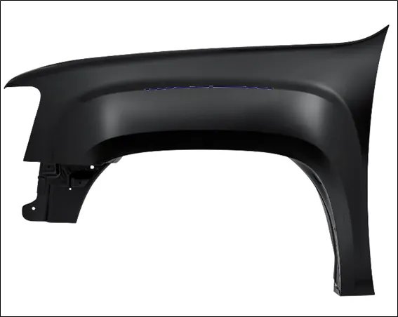
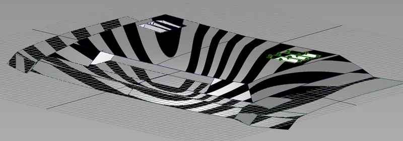
The blueprint of the front fender is provided as a canvas image. Initially curves are made to create as per the image. From these surfaces are created. For certain areas, the surfaces have to be made such it continuous as a part of the car and later trimmed to provide the exact part to be designed. For the hood, the reference image is used as an idea to generate the shape by observing the surface flows. From this the part is created following the process of curve network and surfacing. Also visualization does play a vital role to provide the correct surface flows for that specific section/patch.
Design Methodology :
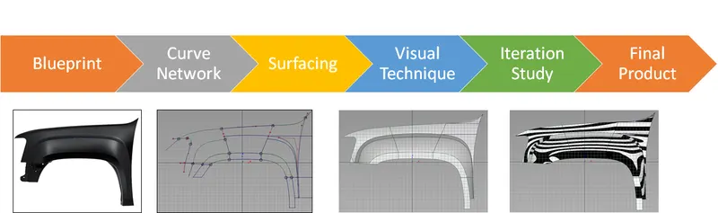
Description :
Front Fender
The blueprint is first setup using the side view.
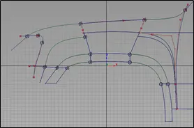
The wheel arcs and main fender structures are taken as elements to create curves like CVs and blends. From this initial squares are created. Mainly, continuity needs to be established depending on surface bends like G2 curvature and G0 position. Next, the wheel arcs main structures are created by same method.
The entire wheel arc and main fender are made of squares and rails. As explained to create continuity, each layer has to be continuous to denote on surface flow. The concept of MS draft is being introduced to provide angular extrusion by viewing the canvas image.
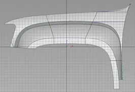
The shape pertaining the hood and A pillar is made by CV and blends to acquire the car continuity to get the idea of the crowning from main fender surfaces. A CV curve is created from the upper end of the fender to the lower end to denote the intersection between the primary fender surface and body panel, thus trimming out the unwanted patch.
From this the body panel is created by adjusting the door end curves to give some crowning and having same path of the CV curve created. The patch is then created by certain patches to achieve one continuous surface. Once established, the hood and A pillar CV is also used to create squares and rails.
The headlight is also shaped by trimming the surface.
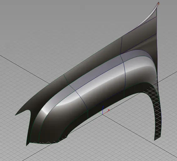
Hence the front fender is created.
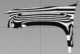
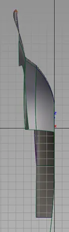
.
Hood
Similar to the methodology followed for creating the front fender, the hood is designed a bit differently.
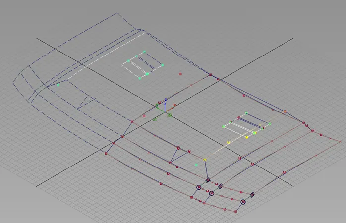
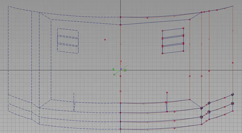
Here the hood is made more by visualizing the curve network from the image as it is displayed in perspective thus it may not provide accurate shapes.
The initial base CV and blend is created and duplicated 3 times to give the hood shape. For the air intake end, the primary CV is duplicated and shaped again to provide the hood shape.
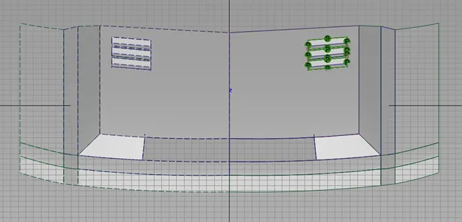
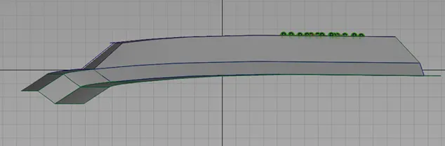
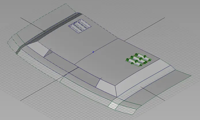
Once the curve network is established, squares are used. The reason being the continuity is smoother compared to skins and rails and it can easily adjusted.
Although, these surfaces need to be shaped for continuity thus enabling the smoothness of the patches.
The alternative method would be used MS draft. But the surface can be controlled easily using CV curves and blends.
After the basic hood is designed, details for the air intakes and air outlets are created by projections and trims.
Conclusion :
In conclusion, the front fender and hood are created by visually observations and surface continuity techniques.