Challenge 5 : Concept Modeling of Car Bumper
Challenge : Modelling of Car front and rear bumper
Objective :
The task is to design a car's front and rear bumper using surface and visualization techniques and reference images to achieve the model.
Introduction :
The blueprint of the car is setup in its front, side and rear view to create the bumpers. The curves are then plotted against the reference canvas images to create approximate wireframe. This is later surfaced using surface tools to create the geometry. By using reference images of the car as a mass produced vehicle, the surfaces are edited by using visualization techniques as diagnostic shaders to achieve the model's originality.
Design Methology :
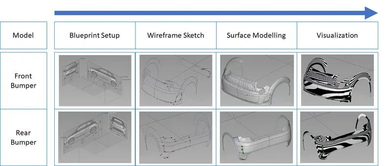
Description :
Front Bumper
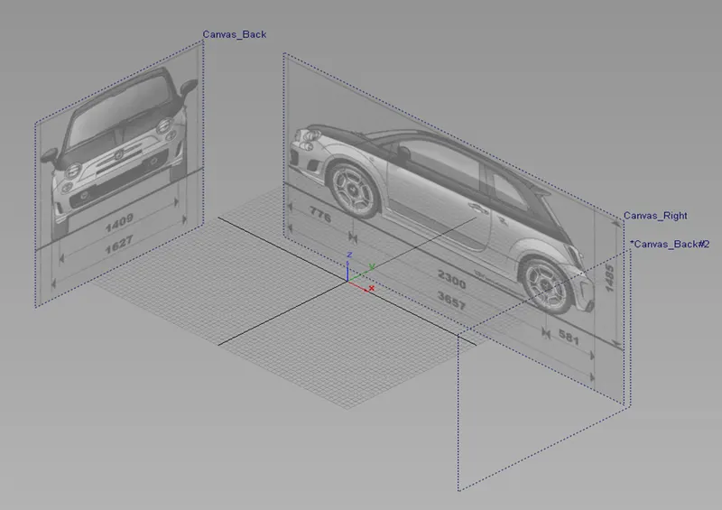
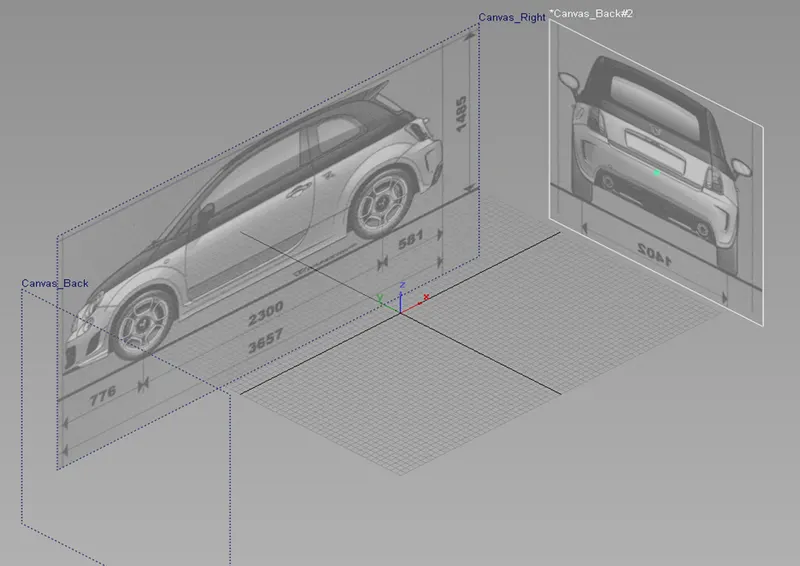
The blueprint is first setup using the front and side view of the car.
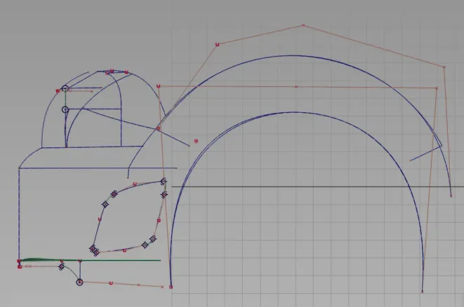
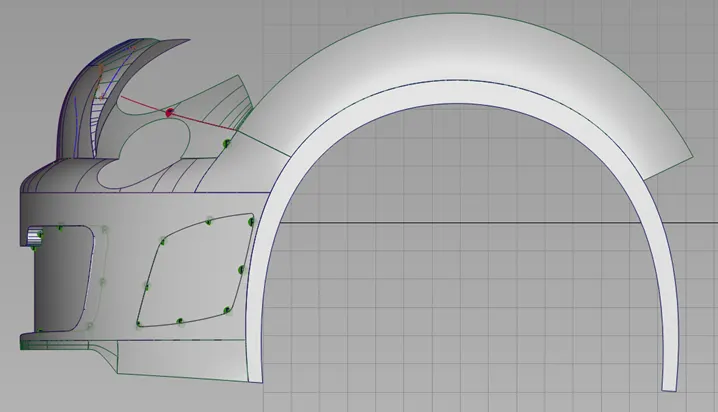
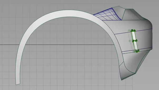
The design process is initiated by creating the wheel arcs using CV curves followed by skin surfacing. The front fender is design roughly to provide the volume and shape extending to the front bumper. The front fender is created by a square.
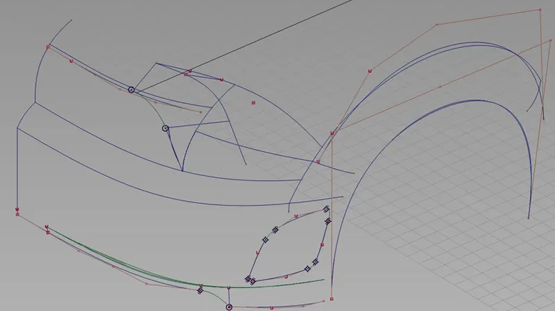
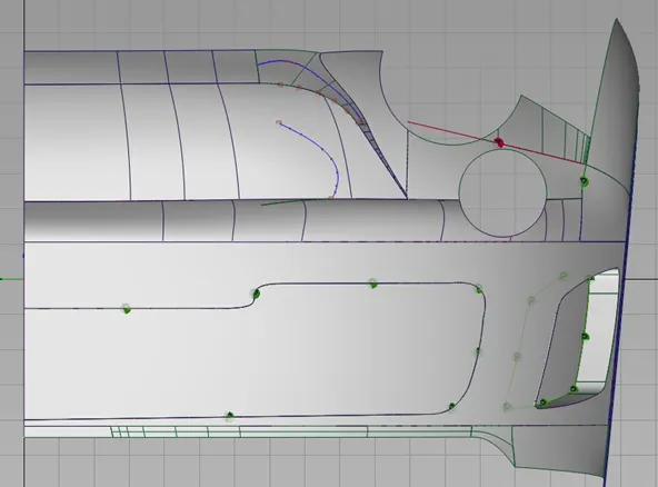
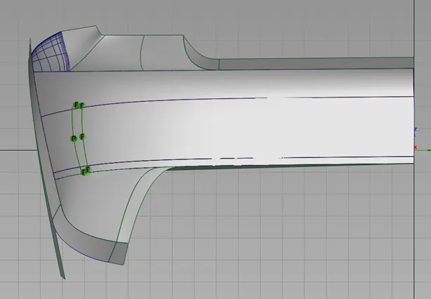
Next from side view, CV curves are created all to the wheel arcs to provide the wireframe shape of the bumper. This is created by square. Once the shape is achieved, the CV curves are duplicated to provide the shape of the upper part of the bumper where the logo is affixed as per the reference and surfaced by rail. The curve line between the bumper edge and the hood is created to provide the upper end of the bumper. This is later extended to the fender to give the headlight structure. All these curves are later used to squares.
Surfaces like the front upper part of the bumper, headlight area and upper end of the bumper are later trimmed off to get the final part.

The headlights, grilles and side air intakes are trimmed/discarded to give the basic feel of the bumper. The grilles and air intakes are created by rails to give the depth of the bumper part.
Rear Bumper
Similar to the methology followed for creating the front bumper, the rear bumper created.
The blueprint is setup by adding the rear view and existing side view.
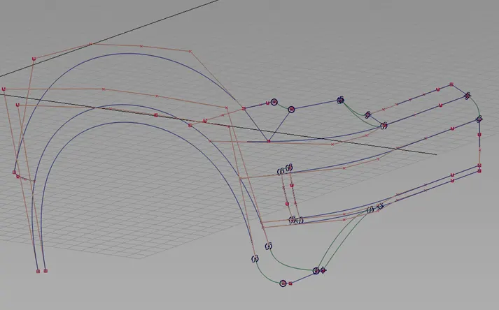
First, the wheel archs are created using CV curves and surfaced using skin. Later the curve is duplicated to make the rear fender. Although it is not seen in the rear bumper, it gives the shape of the rear bumper since fender is bulged as referenced from the live image. It is created but using square.
CV curves are created from side view till the wheel arcs to give the wireframe, thus being created by squares. The end of the wheel arc attached to the lower end of the bumper is made by squares. The part of the bumper where the trunklid mates is first created using CV curves and blends. This is later made by square and bi-rail. Since the tail light has part of the structure in the bumper design, the shape is acquired by CV curves and blend. This is also created by using squares.
Once the basic rear bumper is created, the rear air outlet grille is created by discarding and creating rails.
Conclusion :
In conclusion, both bumpers have been created by using CV cuves, surface elements and using visualization techniques & concept of curve continuity. In the process of creating surfaces, continuities were checked depending on surface contacts w.r.t to the images.