Challenge 5 : Concept Modeling of Car Bumper
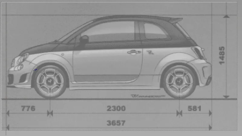
Different views of the front bumper
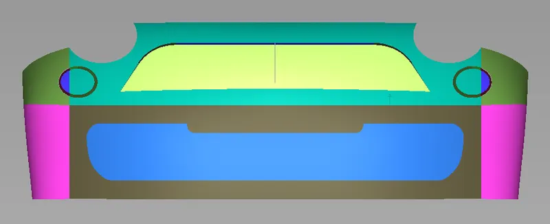
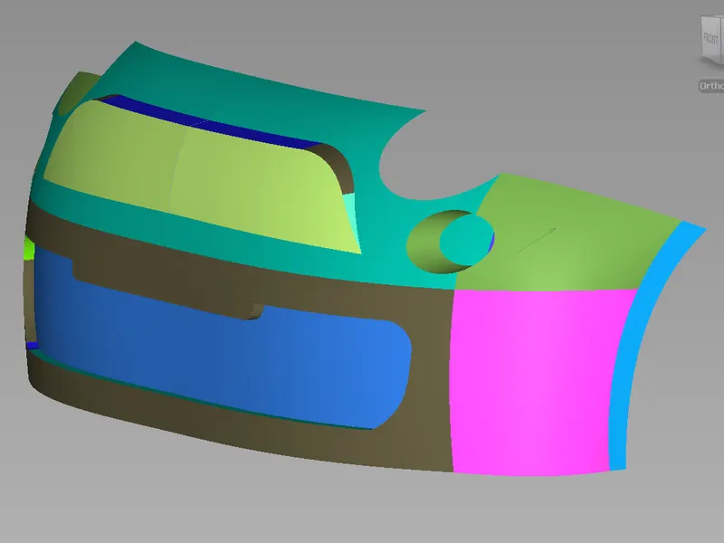
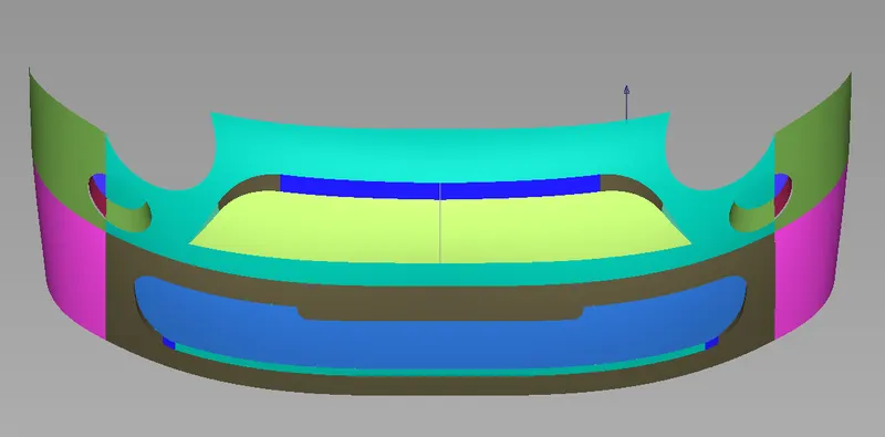
Design procedure:
Create a new image layer
- Choose Windows > Editors > Canvas Layer Editor
 .
. - Select the image layer above which you want to create a new image layer.
- In the Canvas Layer Editor, click the button, or choose Layer > New image layer from the menu.
A blank image layer is added to the canvas plane (above the active image layer) and becomes the active image layer.
Name an image layer
- Choose Windows > Editors > Canvas Layer Editor.
- In the Canvas Layer Editor window, double-click the image layer’s name.
- Type a new name for the image layer and press
 (Windows)
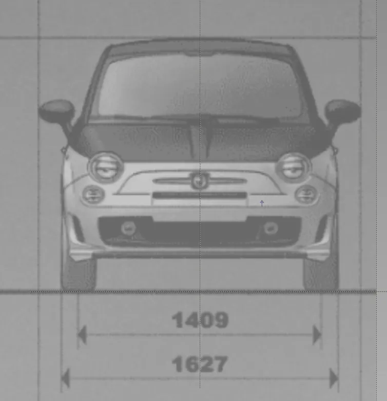
tools used for design bumper
CVs
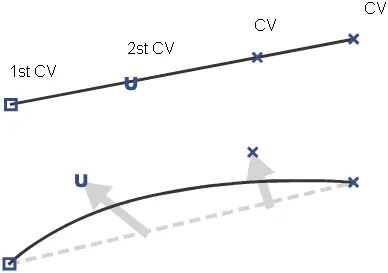
CVs (control vertices) control how the curve is “pulled” from a straight line between edit points. They are the most basic and important means for controlling the shape of a curve. Lines between consecutive CVs form the control hull.
You cannot add CVs to the interior of a curve: there is always a set number of CVs for each span. The number of CVs is equal to the degree of the curve plus one. So, for example, a degree 3 curve has four CVs per span.
Alias draws CVs differently to let you tell the difference between the start and the end of a curve. The first CV (at the start point of the curve) is drawn as a box. The second CV is drawn as a small “U”, to show the increasing U dimension from the start point. All other CVs are drawn as small Xs.
edit points
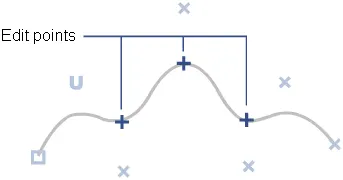
You can tell when a curve is made from multiple spans in several ways. One is to look for edit points on the curve. Edit points mark the connection point between two spans. Alias draws edit points as small crosses.
Unlike the on-curve control points of Bezier curves (used in many 2D illustration programs), NURBS edit points are not usually used for editing curves. CVs control the shape of a NURBS curve, and edit points are just indicators of how many spans a curve has.
lend curves allow you to create curves by specifying constraints on their shape.
Palette tool: Curves > Blend Curve Toolbox 
Blend curves provide higher-level, simpler methods for shaping and manipulating curves. They provide a level of abstraction on top of the actual geometry of the curve. Blend curves let you focus on what the curve needs to do, and have the system calculate the right curve to fulfill those requirements.
Blend curves are normal NURBS curves with more construction history: you can use all the normal curve tools on blend curves, and when you are not using blend curve tools, they look like any other curve.
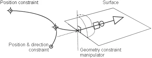
Blend curves are controlled by blend points acting as constraints:
Sweep one generation curve along one rail curve
The procedure for using the Rail Surface tool has several optional steps, depending on the settings in the Rail Surface Control window.
- Choose Surfaces > Swept Surfaces > Rail Surface

 from the tool palette, or double-click its icon.
The Rail Surface Control window appears.
- Make sure Create History is checked.
You almost always want construction history on. This allows you to change the settings after you sweep the curves.
This example uses the following settings.
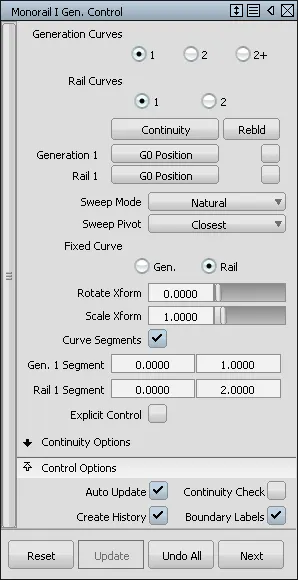
When you are satisfied with the new surface, you can delete the history information with Delete > Delete Construction History
 .
. - Click the generation curve. This is the curve that is swept along the rail curve to create the surface.
The generation curve can be a free curve, isopam curve, curve on surface, or trim edge.
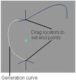
- If Curve Segments is on, use the locators to place the start and end edit points of the generation curve.
- If Sweep Pivot is On Curve or Off Curve, use the locator to set the pivot point of the generation curve.
- Click the locator and drag to move the locator along the curve (On Curve) or in space (Off Curve).
- Type a parameter (On Curve) or 3D coordinate (Off Curve) to set the pivot exactly.
- Click Go to continue.
- Click the rail curve. This is the path along which the generation curve travels.
The rail curve can be a free curve, isoparametric curve, curve on surface, or trim edge.
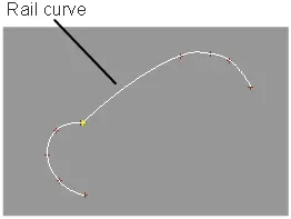
- If Curve Segments is on, use the locators to set the start and end edit points of the rail curve.
- If Sweep Pivot is On Curve or Off Curve, use the locator to set the pivot point on the rail curve.
- Click the locator and drag to move the locator along the curve.
- Type a parameter to set the pivot exactly
- Click Go to continue.
- If the Sweep Mode is Spine, click the spine curve. This curve controls the orientation of the generation curve as it travels along the rail curve.
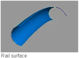
Sweep one or more generation curves along two rail curves
- Choose Surfaces > Swept Surfaces > Rail Surface from the tool palette, or double-click its icon.
The Rail Surface Control window appears.
- Make sure Create History is checked.
You almost always want construction history on. This allows you to change the settings after you sweep the curves.
When you are satisfied with the new surface, you can delete the history information with Delete > Delete Construction History
. - In the Rail Surface Control window, set Rail Curves to 2.
Set Generation Curves to the number of generation curves to use:
- Choose 1 to sweep one curve along the rails.
- Choose 2 to blend from one generation curve to another along the rails.
- Choose 2+ to blend a series of generation curves along the rails.
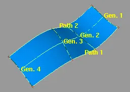
- Click the first-generation curve.
The generation curve(s) can be a free curve, isoparametric curve, curve on surface, or trim edge.
- If Generation Curves is 2, choose the second-generation curve.
If Generation Curves is 2+, pick all the generation curves in order, then click Go.
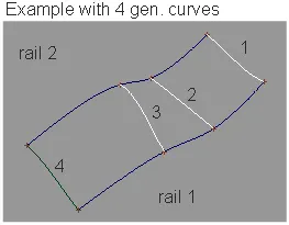
- Click the first rail curve, then click the second rail curve.
The generation curve(s) must intersect both rail curves.
The rail curves can be free curves, isoparametric curves, curves on surface, or trim edges.
Create free NURBS curves with Project
- Choose Surface Edit > Create CurvesOnSurface > Project

The control window opens.
- Set Create to Curves.
- Choose a projection method: Curve fit or Match original.
Note:
Curve fit uses the algorithm from the Curve Edit > Fit Curve
 tool to fit a free curve to the underlying projected curve-on-surface. Match original projects the edit points first, then creates a curve between them.
 - Select the surface(s) on which you want to project a curve, then click the Go button.
The surfaces turn pink.
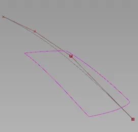
- Select the curve(s) to project then click the Project button.
The curve is projected along the View vector of the active window, by default.
A free curve is created on the surface(s). By default, it has the same degree and number of spans as the original curve.
A deviation locator appears, showing the maximum distance between the projected curve and the surface.
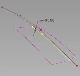
- If you are using the Curve fit method, adjust the Degree and number of Spans of the projected curve if needed.
The projected curve and its maximum deviation locator update accordingly.
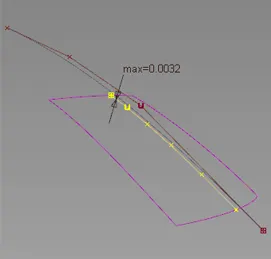
The degree was changed from 3 to 5. The deviation has decreased.
Trim Control
- 3D Trimming
-
If this box is checked, you can trim the surface along projected curves and cross-sections, or you can select a surface and generate a trimming curve automatically from the intersection with the target surface. By default it is unchecked.
- Method
-
Displays when 3D Trimming is selected.
Project – Creates trimming curves by projecting the selected curves onto the target surface.
Intersect – Creates a trimming curve from the intersection of the selected surface and the target surface.
You can use the Project or Intersect method in a single trimming operation by toggling back and forth between them.
- Extend
- Extend a curve that does not project entirely on the patch, either automatically or manually, and continue the trim operation without leaving the tool.
- auto when the trim fails, any curves-on-surface that are within the set Tolerance of another curve-on-surface or boundary are extended and the trim is attempted again.
- selected trim extend arrow appears on the curve that needs extending. Clicking the arrow snaps the end of the curve to the patch edge.
-
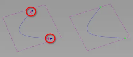
Vector Options
These options are only available if 3D Trimming is turned on.
- X, Y, Z
-
Specifies a projection vector along that axis.
- View
-
Specifies a vector normal to the current view. The vector is not drawn in the view windows.
If the current view is changed, click Refresh View Vector to update the vector.
Note:You can project different curves along with different views vectors. However, if you click Refresh View Vector, or select a different vector option, all curves-on-surface are updated to match the current projection vector.
- Picked
-
Lets you specify the name of an existing vector in the Picked Vector field or pick the vector in the view.
- Normal
-
The curve is projected onto each point on the surface along the normal at that point, instead of along a single vector direction.
- Picked Vector
-
This text field only appears when Picked is selected. It displays the name of the selected vector object. Alternatively, you can type in the name of a vector object.
- Refresh Vector
-
This button only appears if View is selected. Click it to update the vector if the view has been modified
- Retain Vector
-
Click this button to create a vector construction object in the view windows. Otherwise, the tool uses the vector direction you specified, but you are not able to see and re-use the vector.
- Create Vector
- Click this button to create a projection vector.
Click in the view to place the start point of the vector, or type the position and press. Use the vector manipulator to position the vector then click Accept.
Control Panel > Curvature

Checks curvature on curves and surfaces with combs and min/max locators.
Use the curvature icon to view and modify curvature combs. You can view a curvature comb on a curve, or on a surface in the U and V directions.
Note:You only see the curvature comb display if either a curve or a surface is selected, and Curvature U and/or V is turned on in the Display section of the Control Panel.
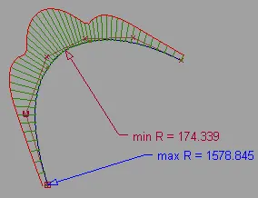
Curvature combs can also be displayed on a surface cross-section through the Cross-Section Editor options. See Windows > Editors > Cross Section Editor.
To view a surface curvature as a color map on the surface, use the Curvature Evaluation mode under Diagnostic Shading on the Control Panel.
See Curvature Evaluation.
Horizontal/Vertical (Zebra) diagnostic shader
Displays horizontal or vertical highlights on the surface. Useful for identifying surfaces that do not meet smoothly (surfaces have mismatched tangents).

This mode shows horizontal or vertical highlights on the surface.
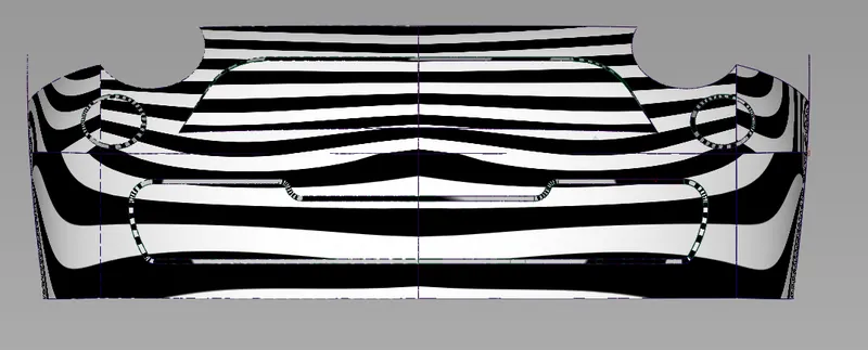
Horizontal/Vertical highlighting helps you find surface flaws. A common use for this is the identification of adjacent surfaces with mismatched tangents—in other words, surfaces that do not meet smoothly. You can also use Surface Continuity for this purpose, but Horizontal/Vertical highlighting gives you a clearer view of the surfaces.
This mode lets you sweep multiple black and white highlights across a surface. You can see where the highlights do not move smoothly. A jump in the highlight flow indicates flaws in either the surface or its boundary with a second surface.
Horizontal/vertical zebra stripe options
This mode shows horizontal or vertical highlights on the surface.
Note:Highlighting helps you find surface flaws by using a color texture to simulate natural highlights. It maps a color pattern onto a surface based on the angle (from 90 to -90 degrees) at which a viewing ray hits the surface.
Note:A common use for highlighting is to identify adjacent surfaces with mismatched tangents. (You can also use Surface continuity for this, but highlighting gives you a clearer view of the surfaces.) Also note that not all Alias packages include the highlighting features.
- Vert., Horz.
-
Sets the highlights to be vertical or horizontal.
- Lock Texture
-
Normally the highlights are projected from the camera, so the projection changes as you move around the surface. (This is the unlocked mode.) You can turn this option on so that the texture remains locked relative to the surface.
- Repeats
-
Sets the rate at which the texture repeats. Increasing this number will increase the number of highlight lines on the surfaces.
- Transparency
-
Sets the transparency of the shaded surfaces, from 0.0 (totally opaque) to 1.0 (totally transparent).
- Thickness
- Controls the thickness of the bands inside the texture.
- Ambient Light
-
Slide to set the level of ambient light, an illumination that comes from all directions and lights all objects uniformly. The slider ranges from 0.0 (no illumination) to 1.0 (maximum illumination).
- Diffuse Light
-
Slide to set the ability of objects to reflect light in all directions. The slider ranges from 0.0 (no light is reflected) to 1.0 (all light is reflected).
- Link Light to Camera
-
When this option is checked on (default) the light source for the shading comes from the camera (like a headlight), so that the highlights move over the model as you tumble around it.
Checking off this option un-links the light source from the camera and locks it to its current position, so the highlights remain stationary as you tumble. It also displays two sliders and a manipulator that lets you rotate the light around the model.
Note: The center of rotation is calculated at the moment Link Light to Camera is checked off. It corresponds to the tumble center used when tumbling with Alt + Shift + left mouse button (with Tumble Center set to World Point in View > World Move Camera >Tumble). Setting a point-of-interest (POI) on the geometry or doing a View > Look At modifies the tumble center, hence the center of rotation. - Light Azimuth
- Azimuth values range from -180 degrees to 180 degrees and rotate the light horizontally.
- Light Elevation
- Elevation values range from -90 to 90 degrees and rotate the light vertically.