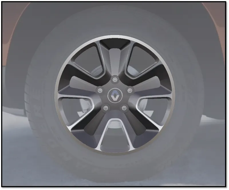
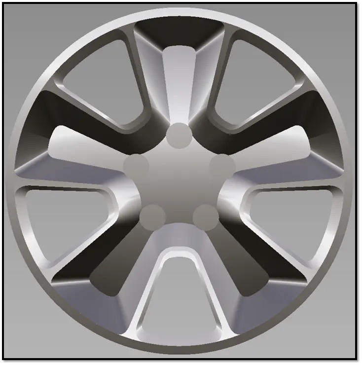
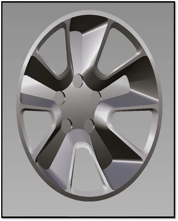
Challenge 4 : Concept Modelling of Alloy Wheel
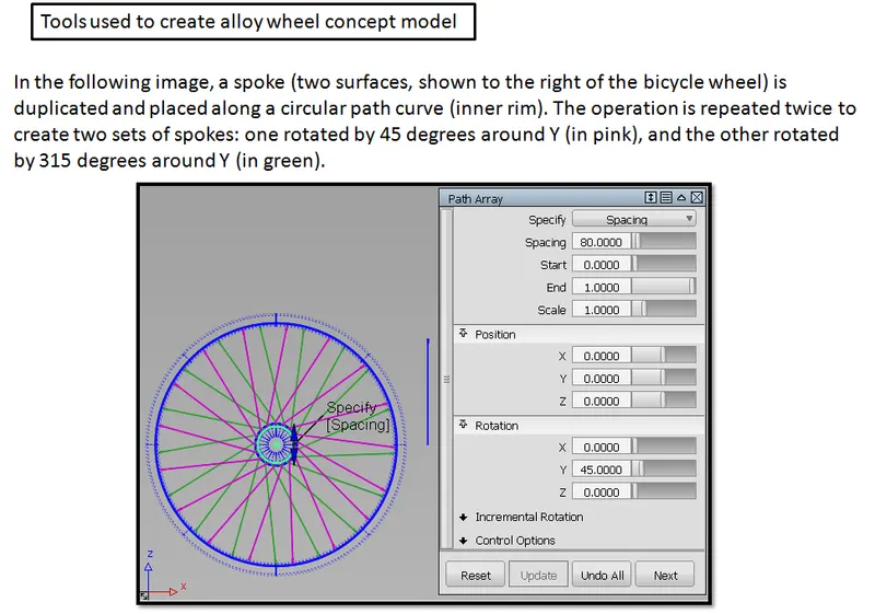
Align surface edges
This aligns one surface to one or more surface edges, trimmed edges, curves, curves-on-surface, or isoparametric curves.
- Choose Object Edit > Align > Align

 .
.
Edge is the default Alignment Type.
- Click the edge of the surface you want to align (the Input).
- Sequentially click the edges of the surfaces you want to align to (the Masters). These can also be curves, isoparms, curves-on-surface, or trimmed edges.
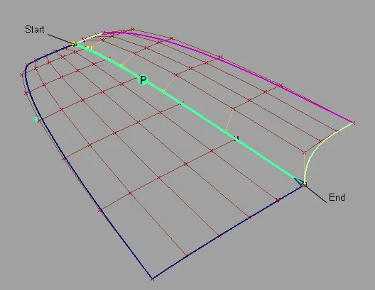
- Align the edges with the Position Influence slider to help achieve positional continuity if needed.
When the value of the slider is 0.0, the surfaces being aligned keep their parameterization intact. As the slider is moved to 1.0, it attempts to match the parameterization of the Master surfaces, which results in a better fit.
- Set the continuity level to G1 Tangent, G2 Curvature, or G3 Curvature in the Continuity section of the option window, if desired.
Manipulator arrows allow direct manipulation of the tangent and curvature lengths.
The arrows on the outside of the surface provide independent scaling of the tangent and curvature lengths on each side. The arrow in the middle of the tangent or curvature rows moves all the CVs in that row by the same amount.
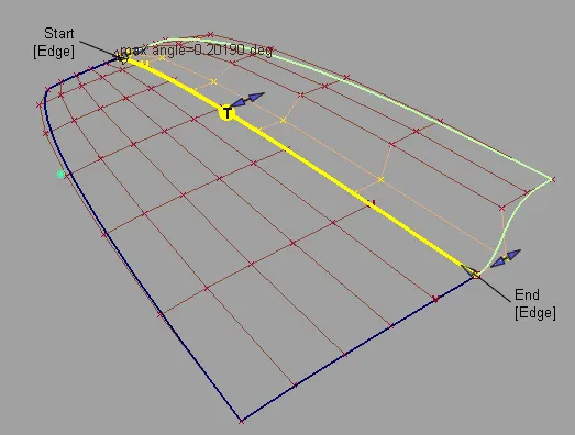
If the requested continuity is not achieved, try one or more of the following:
- Adjust the Position Influence slider. It will help line up the CVs along the boundary.
- Turn on Tangent Balance to try and match the hull shape of the Master surface, or adjust the tangent lengths along the edges with the manipulators.
- Turn off Explicit Control. This will automatically set the degree of the Input to that of the Master in the direction of the alignment. You can also manually adjust the degree and number of spans through the option window.
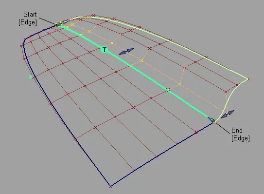
Here Position Influence has been set to 1.0 and Explicit Control turned off to match the degrees. Notice how the CVs now line up perfectly across the boundary.
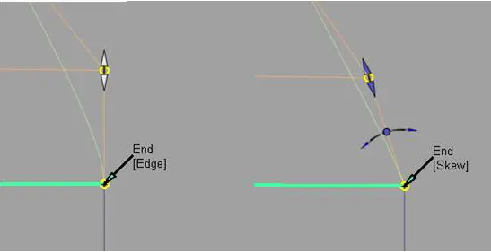
- Change the outside edge alignment by clicking the Edge label to toggle between Skew or Edge Align. Or set Start Align and End Align in the Outer Edge section of the options window.
When Skew is selected, a rotational manipulator becomes visible which allows direct modification of the skew angle. You can also specify a specific Skew Angle value in the options window.
When Edge Align is selected and you are aligning to a natural surface boundary, you can turn on Tangent Balance to adjust the CVs on the tangent row so that the tangent lengths of the Input surface match those of the Master. The same applies to the curvature row CVs if G2 Curvature is on, and to the next row of CVs if G3 Curvature is on.
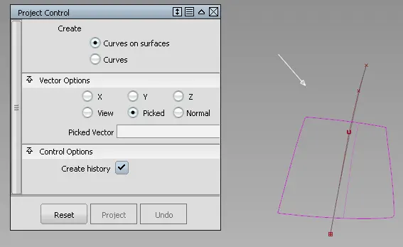
The Project tool lets you specify and change the projection direction from within the tool, as described in the workflow below. By default, the tool projects along the view vector of the current window (that is, the direction the camera is looking at). You can also use an external reference vector to specify the projection direction.
projection curve on surface
-
In the Surface Edit tool palette, select the Create CurvesOnSurface > Project tool
 , then the icon.
The control window opens.
-
Make sure that Create is set to Curves on surfaces.
-
Select the surface(s) on which you want to project a curve, then click the Go button.
The surfaces turn pink.
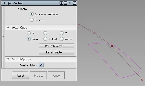
-
Select the curve(s) to project then click the Project button.
The curve is projected along the View vector of the active window, by default. A curve-on-surface is created on the surface(s).
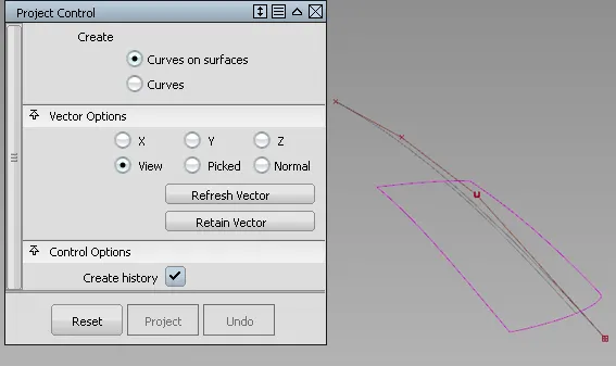
-
Change the view in the Perspective window, then click the Refresh View Vector button. (You can also change the view to that of a different window by clicking in it).
The curve-on-surface updates according to the new view vector in the Perspective window.

-
In the control window, choose a different vector option such as X, Y, Z, or Normal.
The curve-on-surface updates.
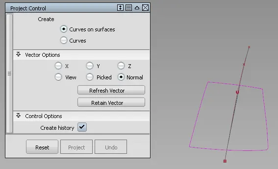
-
In the control window, choose the Picked vector option, then select a vector object.
The name of the vector appears in the Picked Vector field. The curve-on-surface updates according to the picked projection vector.
-
Exit the tool (for example choose Pick > Object
 ).
).The control window disappears.
-
In the Object Edit tool palette, select the Query Edit tool, and then select the curve-on-surface.
The Project tool control window opens. You can modify the options and watch the curve-on-surface update. This only works if the curve-on-surface was created with construction history.
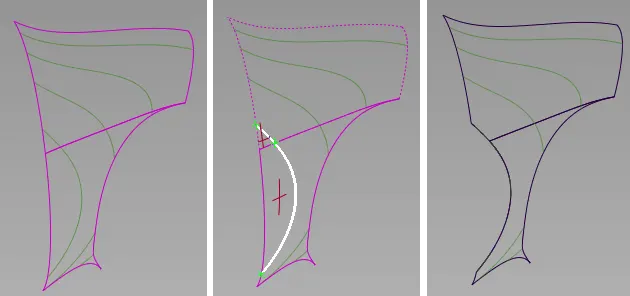
Trim a surface
You can trim more than one surface at a time, using one or more projected curves or intersecting surfaces.
Trim or divide a surface by projecting curves on surfaces
- Choose Surface Edit > Trim > Trim Surface
 .
. - In the control window, turn on 3D Trimming and choose Normal under Vector Options.
- Select all the surfaces you want to trim. Hold down the
 key to pick more than one surface, or use a pick box.
 - Select the curves you want to project onto the surface to create trim curves (curves-on-surface). If the desired curves-on-surface are already present, you can skip this step.
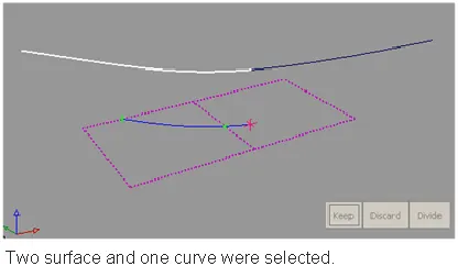
Click on the regions of the surfaces that you either want to keep or discard. (Regions are areas delimited by curves-on-surface). If the trim regions are spread across multiple surfaces, you can box-select them.
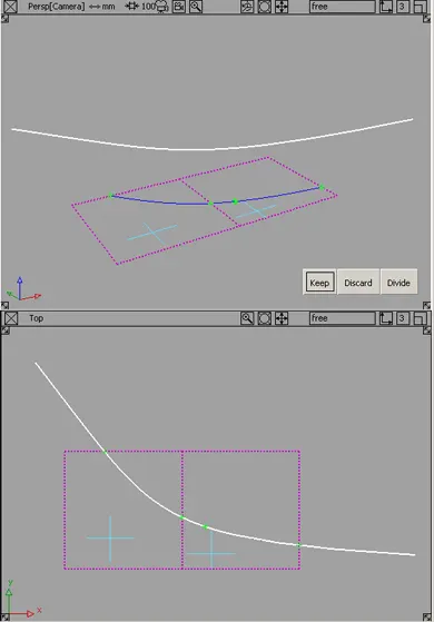
Crosshairs appear on the selected regions. To move a crosshair, click it and drag.
If those region selectors appear too large or too small on your geometry, you can adjust their size by using the Region Selector U Size and V Size sliders in the control window.
Click one of the buttons: Keep, Discard, or Divide, depending on the type of operation you want to perform.
Keep: Keeps the regions selected in step 5, and discards the rest.
Discard: Discards the regions selected in step 5, and keeps the rest.
Divide: Divides the selected regions from the others (making separate trim surfaces) but keeps all the regions.
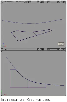
Trim or divide a surface along the intersection of another surface
- Choose Surface Edit > Trim > Trim Surface .
- In the control window, select 3D Trimming and choose Intersect as the method.
- Select all the surfaces you want to trim. Hold down the key to pick more than one surface, or use a pick box.
- Select the intersecting surfaces you want to use to create the trim curves (curves-on-surface).
As you select surfaces and intersecting surfaces, the trim curves are automatically created and displayed on the surfaces.
Note: If you box-select several surfaces, and some of them are already selected for trimming, Alias picks the unselected surfaces and intersects them with the selected surfaces. - Click on the regions of the surfaces that you either want to keep or discard. (Regions are areas delimited by curves-on-surface). If the trim regions are spread across multiple surfaces, you can box-select them.
Crosshairs appear on the selected regions. To move a crosshair, click it and drag.
If those region selectors appear too large or too small on your geometry, you can adjust their size by using the Region Selector U Size and V Size sliders in the control window.
Tip:You do not have to click a “visible” part of the surface (such as an isoparametric curve). Clicking anywhere inside the surface edges will also work.
- Click one of the buttons: Keep, Discard, or Divide, depending on the type of operation you want to perform