Concept Modelling of Alloy Wheels
Aim - To make an Entire surface Models of Car Rims.
Objective - Our objective here is to make surface models of the car rims, 1) Provided by Skill-Lync and 2) Anyone of Our Choice, Surfacing is to be done using Auto Desk ALIAS
Introduction -
Surfaces and Solids, in simple terms both, are just same but the core difference between both is just that surfaces do not form a closed watertight model (or a body or a part), on the other hand, solid does it. Also, Solid models are nothing but a combination of surfaces combined (Knit) together to form a desired closed/patched Model. This will have a Volume to it and since we have the dimensions of the sides/boundaries (surfaces dimensions) we can easily obtain the mass from it. Another difference, however, is that surfaces are more of a visual work, which we do to obtain the desired shape, on the other hand with solids it's hard at times when we have complex shapes and use of surfaces makes it easier to do it. So we approach with surfaces and at the end when we have got what we wanted we can easily close the open edges and make it a closed watertight Model/Body/Part. Now,
Autodesk ALIAS which is an Automotive software deal with surfaces. Since its an Automotive software it's fair to say that it might be Computer-Aided Industrial Design (CAID) software and for the matter of fact, it is, if we talk about CAD (Computer-Aided Design) however, again both (CAD and CAID) almost seems identical but there are some noticeable differences, CAID follows a thought process which requires conceptual imagination and visualization. Whereas CAD deals with Technical terms/data. This difference only, makes our mind that why is ALIAS a CAID software. Its entire work is dependent on the Visualization and the thought process of the software user, it's a very powerful software with having many and many tools which can be used to achieve the final desired shape of the model.
Our task here is the same, to visualize and create the Surface Model and try to get as close as it can be.
Approach -
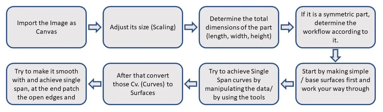
Work Process –
Since most of the work we have to do it with curves, we have used different tools to create Curves.
- CV Curves.
- Keypoint Curves
CV Curves we have used to trace the image. Keypoint Curves we have used for dividing the work as these curves are editable and have dimensions.
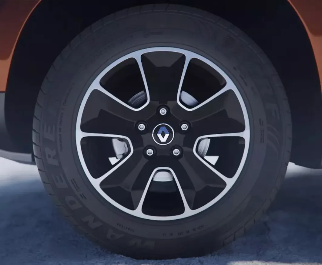
Main Image (Provided by Skill Lync)
Consider the curves shown below –
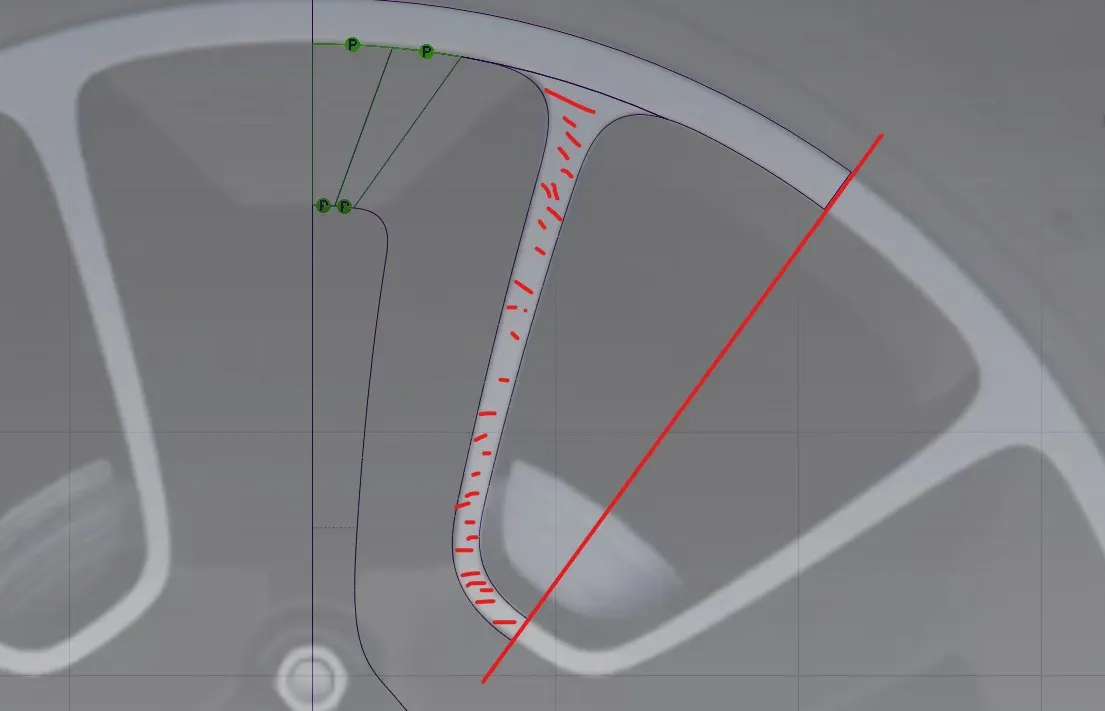
Fig. 1.1 – Rib Selection and division at an angle of 54 degrees (visual)
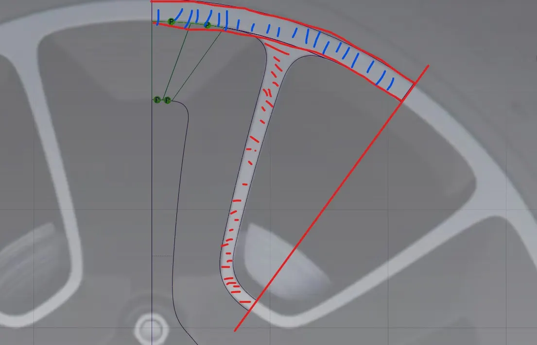
Fig. 1.2 – OD (Outer Diameter)and Rib Curves
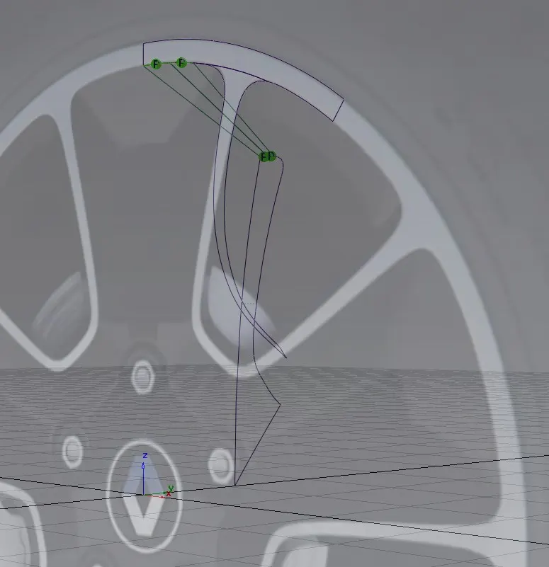
Fig 1.3 – Curve Generation with Volume.
As Curve generation is done we will have to convert it to surfaces
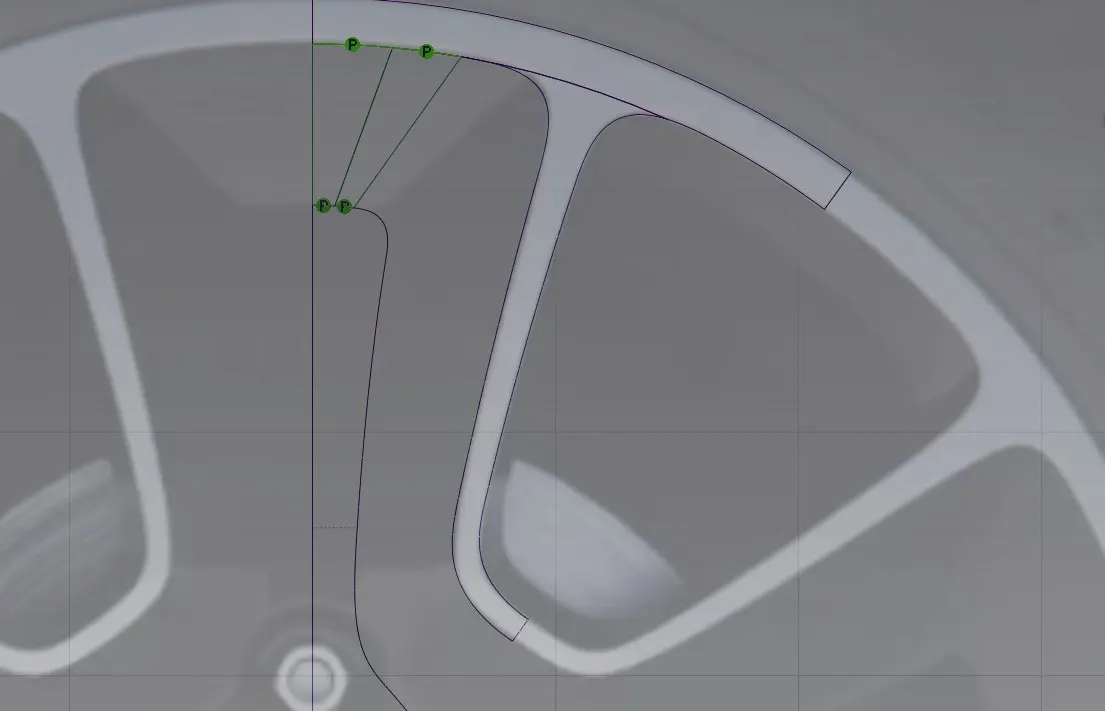
Fig 1.4 – Surface Generation
Features used for creating the surfaces –
- Skins
- Rail
- Square
- Blend
- Intersection
- Project Curve
- Trim / Un Trim
- Detach
Above mentioned features are used to create the below-shown image of the fully formed surface of the Rim.
Note – It's not necessary to use all the features to create the surfaces every time in the end what matters is the FINAL SHAPE of the Part, it does not matter what features you have used. We can use what feature we want to depend on our ability and our own convenience, so the steps are not fixed it's all practical at the time of creating the same (the part/surface model).
However, we need to assure that all the curves are aligned and the surfaces are smooth and if possible, all the surfaces are having a single span. Again, it's not possible to maintain a single span for all the features so, we can use multiple spans where it is not possible to maintain a single span, e.g. the bolt slots.
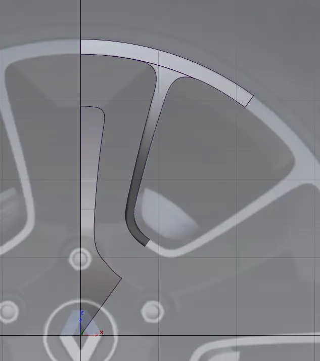
Fig 1.5 Single part Surface
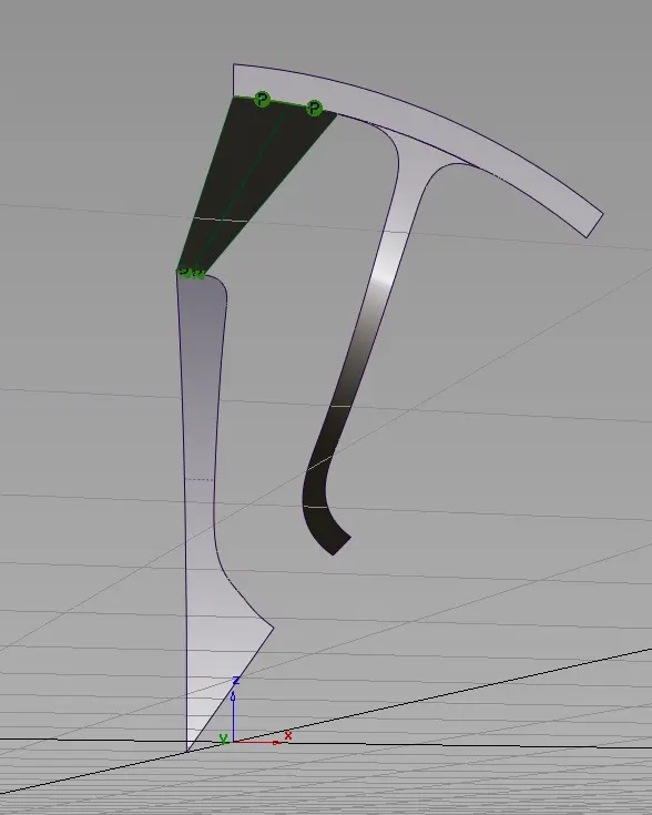
Fig 1.6 Perspective view of the single surface
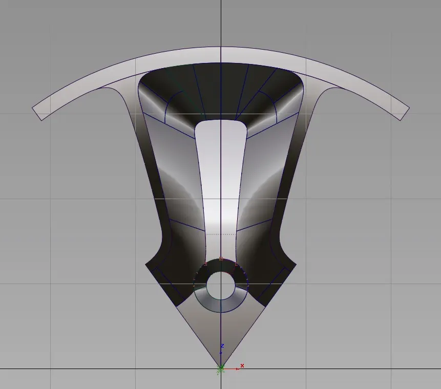
Fig 1.7 – Full Part SUrface with visual enhancement
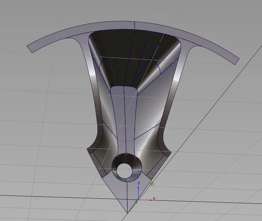
Fig 1.8 - Perspective view of the enhanced surface
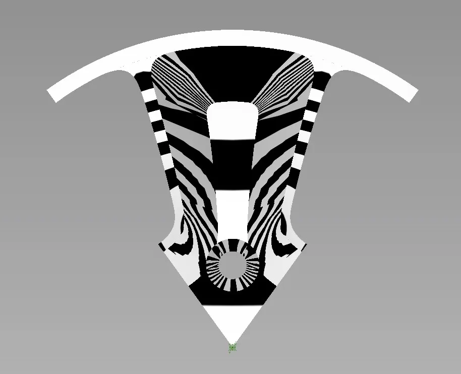
Fig 1.9 - Visual Identification and checking of the surface continuity and transitions
ALIAS provides several visual checks for the surface to determine that id the surface up to the mark? (Smooth and the transitions is smooth and continuous) the MOST important feature is ‘horver’ as it can be seen in the image itself. We have achieved acceptable transitions and the small areas are having smooth surfaces however there are some areas left which do not have the smooth transition.
Next, we just need to make the pattern or duplicate the objects and for that, we need to group the whole surface by selecting and using the command (ctrl + g) to group all together and then moving the pivot point to the centre so that the desirable rotation is correct.
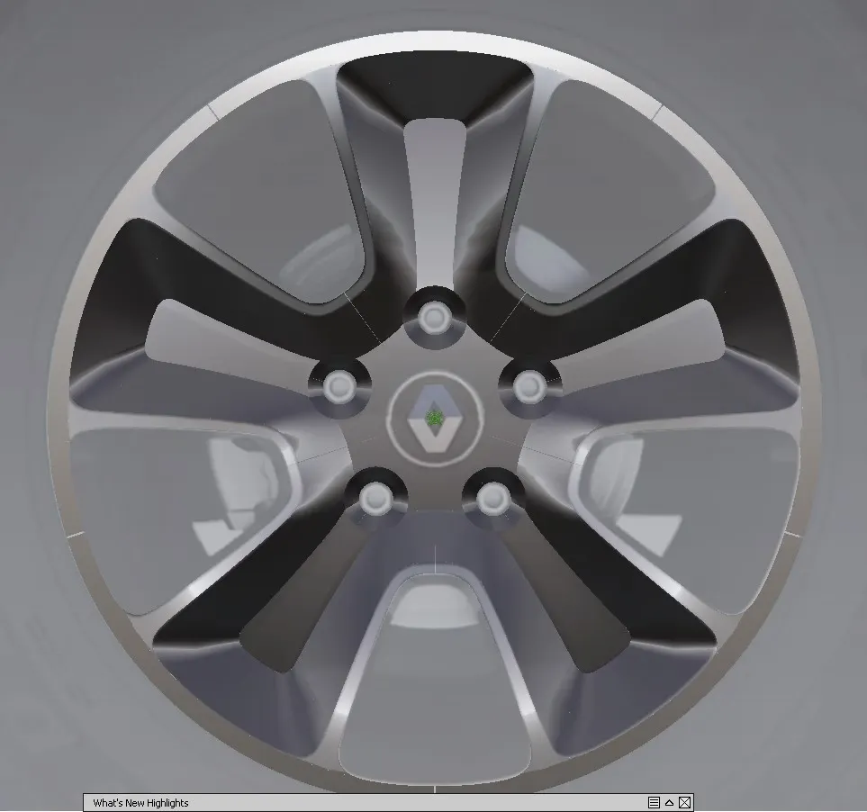
Fig 1.10 – Final Rim
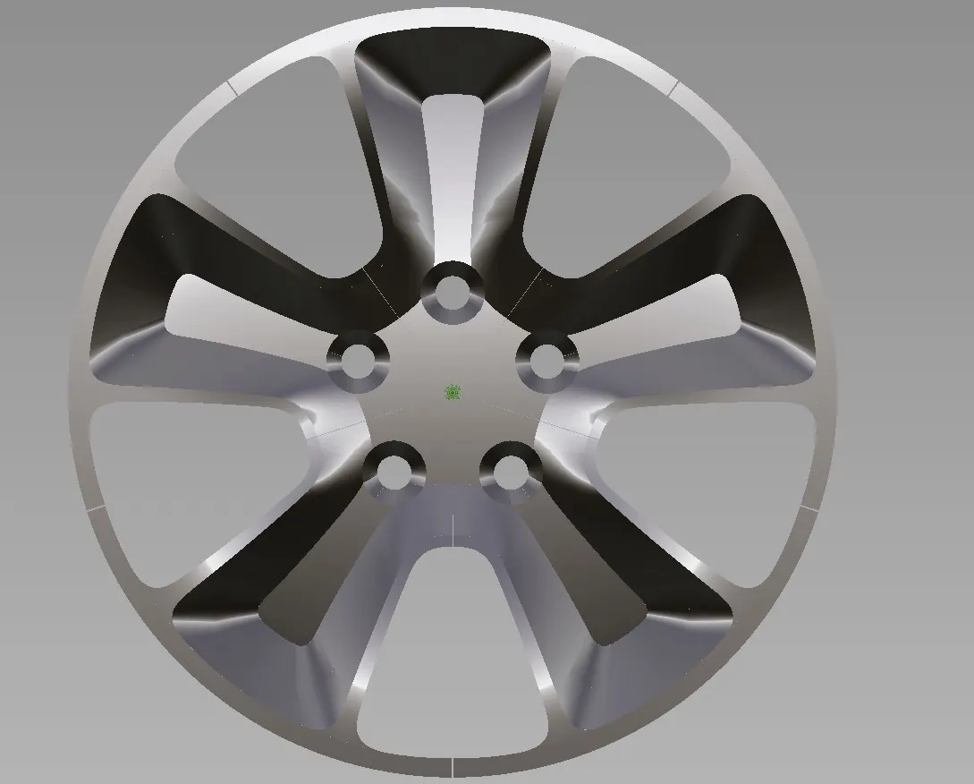
Fig 1.11 – Front view
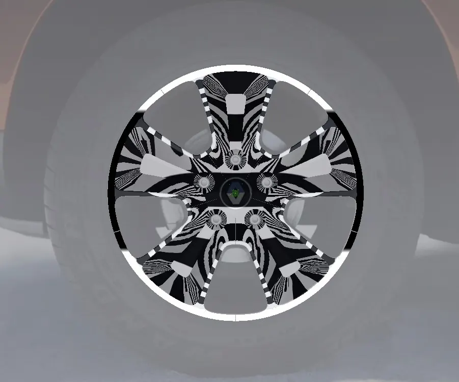
Fig 1.12 - Full Rim Visual Check
Final Images for better visualization -
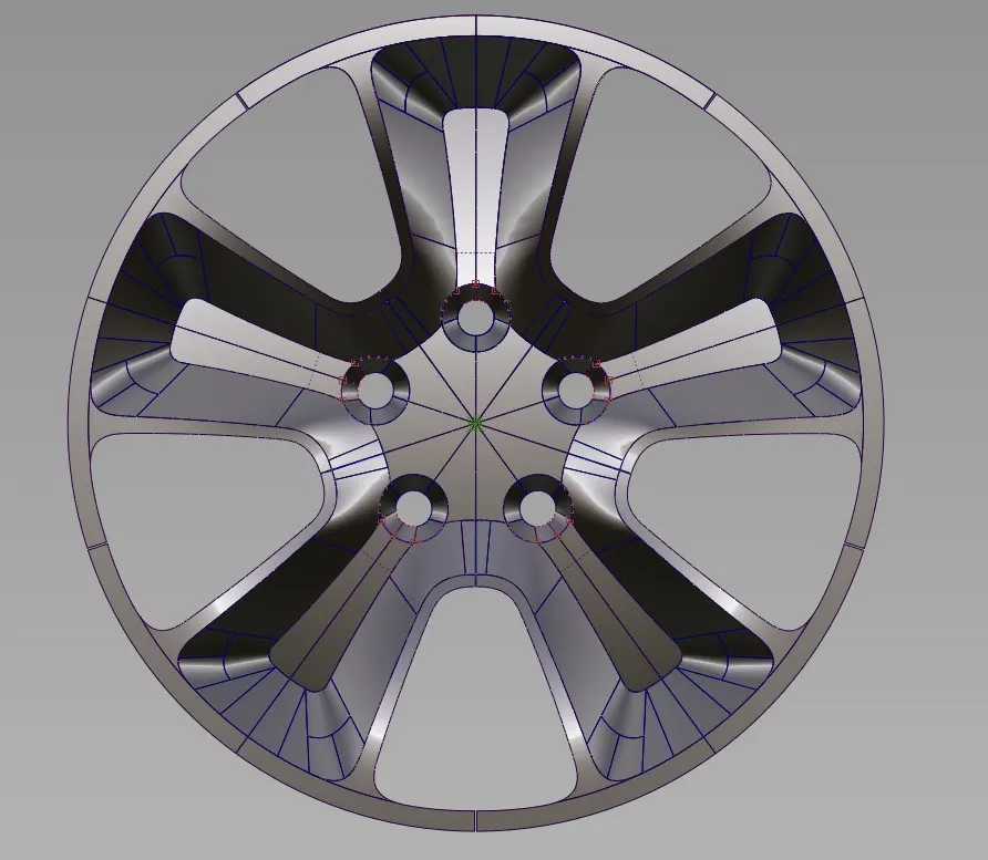
Fig 1.13 Front View
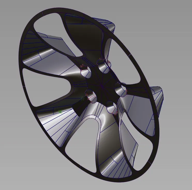
Fig 1.14 - Isometric View
Before Conclusion, we will now use our own personal selected RIM image of which is shown below -
Personal selected Rim -
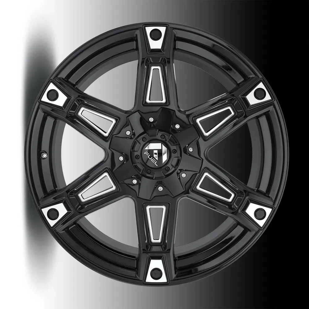
NOTE - The above image is selected on the basis or personal convenience and Knowledge on surfacing the EXACT surface model is not formed some changes are made during the model formation process.
As discussed above we have created the base first and then created the complex parts, since we are not following the method and process we are doing it based on our knowledge, so we have utilized the display and layer options more often.
These are the features which we have used to better understand and visualize how the curves are and what we have to select to avoid a bad and ugly curve network. This way we have divided each step and assigned it to the layer, which is a very helpful feature.
Description -
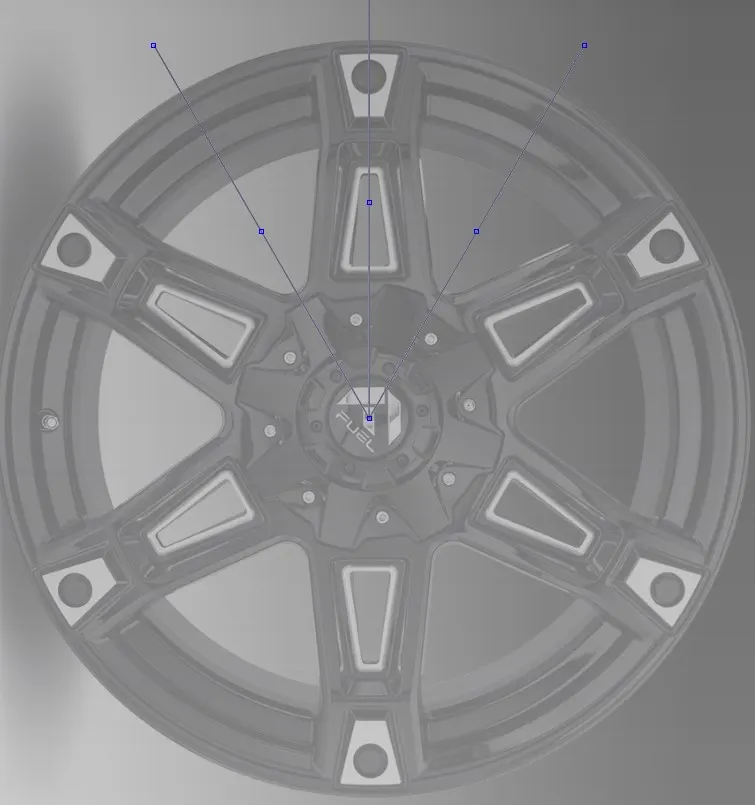
Fig 2.1 - Imported the Image
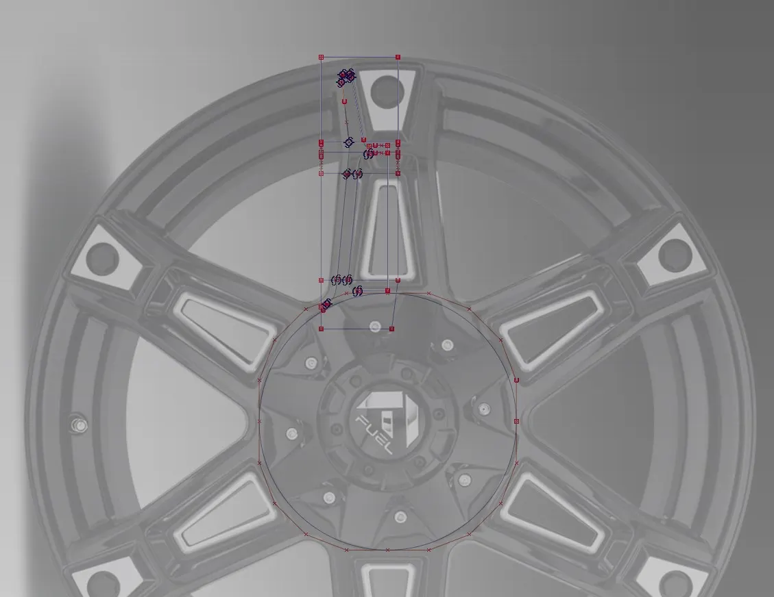
Fig 2.2 - Curves making
Here v=we have made the base curves and we will make that as a surface and then we have created another set of the curves which shows the Rib, we will then be projecting it on the base surface and then we will trim out the unwanted surfaces.

Fig 2.3 - Assigning every completed step to a separate layer
After it has been done we have followed the same approach (Creating the curves and then surfaces) however, instead of making a base curve/surface and projecting the same we have used curves directly and then formed the surface based on the connected curves as it can be seen from the image below,
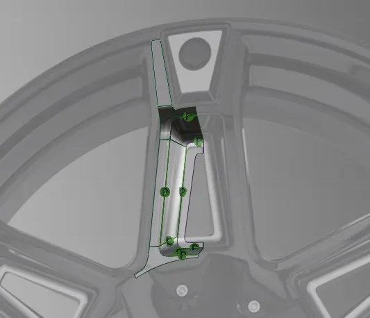
Fig 2.4 - Curves from surfaces
Next, we have to create the upper side, by following the same methodology,
Before that, we now know based on our experience, that what kind of tools we need frequently, so for that there is a simpy way to access it, which is using SHELVES
"Shelves" is a window which stores the user-defined set of the tools. so have stored the tools/features we need frequently e.g. -

Fig 2.5 Shelves
Shelves save time and improve productivity in longer projects like this.
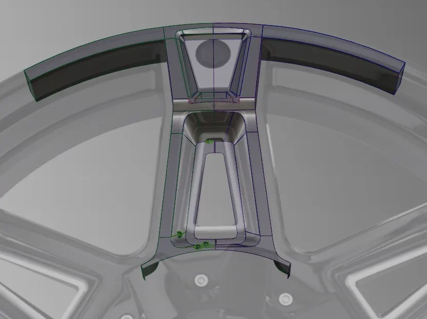
Fig 2.6 - Fully Formed Rib
Now as we know we have to check the patches and we need to visualize that is our surface model smooth and has continuity.
Consider the following image -
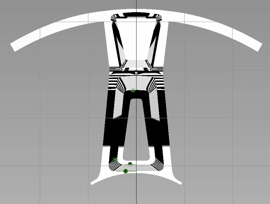
Fig 2.7 - Overall
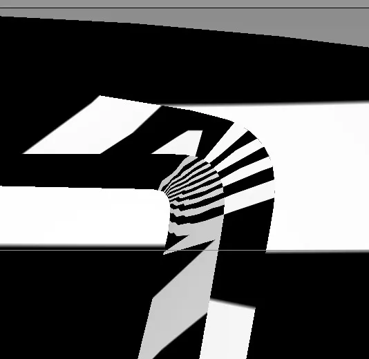
Fig 2.8 - Close corners
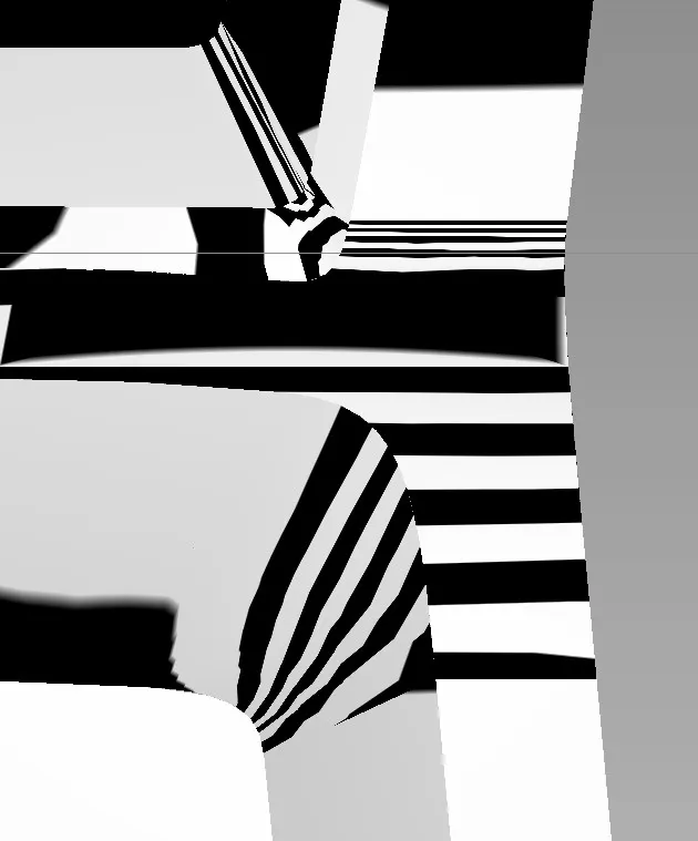
Fig 2.9 Tight Corners
Above transition is acceptable until and unless we are not aiming for class A surfacing.
Now we have almost reached the end of the model, next we will make the holes and middle part and duplicate the model.
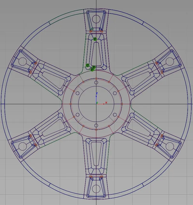
Fig 2.9 - Full Rim front wireframe
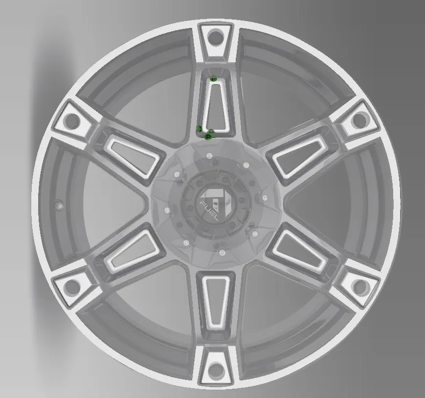
Fig 2.10 - Front
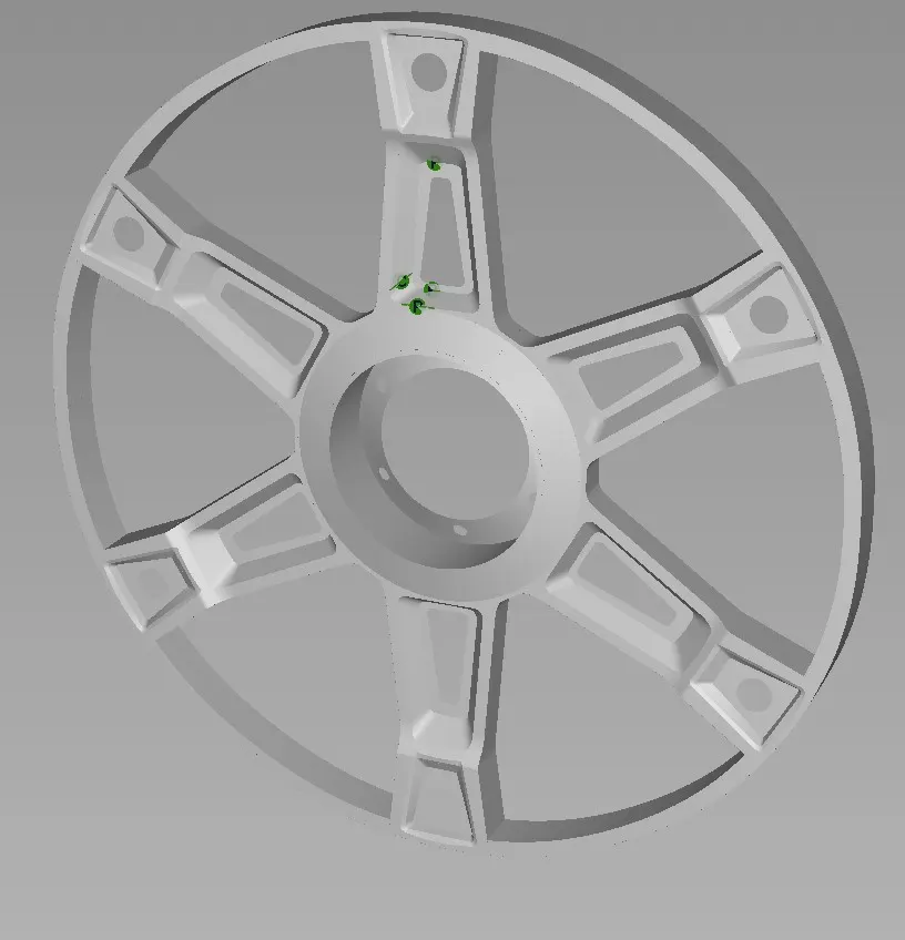
Fig 2.11 - Perspective Front
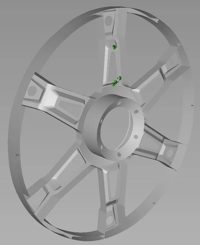
Fig 2.12 - Perspective Back
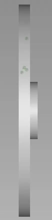
Fig 2.13 - Side
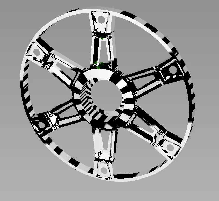
Fig 2.14 - Visual Check
Attachments -
For software files of Autodesk ALIAS, please refer to attachments section -
1. Skill Lync Rim.
2. Final Rim.
Conclusion -
After performing these tasks and making a new Rim on our own, we came to know that how to actually form the desired surface. Rather than tracing the curves and making the surface does not always work, so we need to increase our thought process capacity and think on how to achieve the desired shape. After making my own rim I am now somewhat capable of making complex surfaces, and also able to achieve smooth transitions between surfaces. Moreover, my VISUALIZATION capability has increased which helps me in simplifying the task that I want to achieve. Also from the video, I have learnt how to perform certain task faster and easier.
Improvements needed -
I have realised that, altho my surface transitions are smoother at an acceptable level, but the patches at some areas are not perfect. I am not able to achieve good patched surfaces fully.