Multi Body Dynamics Simulation on IC Engine Valve Train
AIM – Motion Study of CAM valve assembly using Solidworks Motion.
Objectives – Our objective here is to do Motion Study of CAM valve while performing following –
- Results
- Valve lift
- The Contact force between –
- CAM and Push Rod
- Pushrod and Rocker Arm
- Rocker Arm and Valve
- Creating 3D modles of –
- 3.5mm CAM
- 6mm CAM
Modelling of CAM will be done the help of formula provided by Skill-Lync.
1 Modelling –
As per given video, we have created solid MODLES of all the Parts viz. CAM, Push Rod, Rocker Arm, Valve and Valve Stem. Now we have to variate the CAM as given below and perform the motion study for each and every case.
|
Sr. No. |
Wrist Pin Offset (mm) |
CAM Speed (Rpm) |
Material |
|
Case 1 |
6 mm |
1500 |
Cast Carbon Steel |
|
Case 2 |
3.5 mm |
1500 |
Cast Carbon Steel |
Table – 1.1
- Changes for Case 1 –
We have just need to adjust the parameters of CAM i.e. (CD (centre dist.), Diameters of circles), which is shown below, as per Case 1 we have 6mm, the dimensions for 6mm and 3.5 mm CAMs which are used are shown below as well –
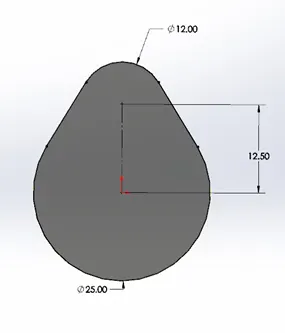
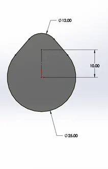
Fig – 1.1
2 Assembly –
In order to perform Motion Study, we have created Assembly consisting of all parts mentioned above.
2.1 Assembling the Parts Together –
Basically, we need –
- CAM to have 1 rotational DOF (Degree of Freedom)
- Attach Push Rod to CAM
- Connect Push Rod and Rocker Arm
- Adjust Valve and Valve Stem
In order to do that we have to fix the DOF (Degrees of Freedom) which are not needed, there are in total 6 Types of Degrees of Freedom –
- 3 Translation Motion (Along X, Y and Z Axis)
- 3 Rotary Motion (Along X, Y and Z Axis)
Follow the Steps below –
Step – 1 (CAM)
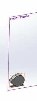
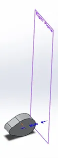
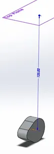
Fig 2.1
After following above figures CAM will only able to rotate at given offsets.
Step - 2 (Push Rod)
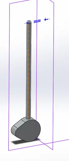
Fig 2.2
Above figure shows the placement and Restriction of DOF of Push Rod.
Step - 3 (Push Rod with Rocker Arm)
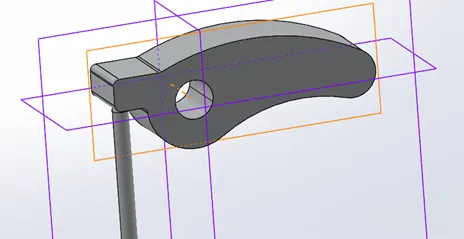
Fig 2.3
Just like what we have done with CAM we have done the same thing with rocker but change in here is that it is not at an offset with TOP plane instead its coincident with TOP plane.
Step - 4 (Valve and Valve Stem)
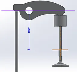
Fig 2.4
Now initially Valve will not be at its place as shown in figure, we can make the assembly connected to each other by using Physical Contact feature.
3 Motion Study –
Now in order to perform the Motion Study, we need Solidworks Motion “ENABLED”.
We need to perform motion study for the Linear Displacement of Piston Head having different locations o wrist pin. For that we are having the table
|
Sr. No. |
Wrist Pin Offset (mm) |
CAM Speed (Rpm) |
Material |
|
Case 1 |
6 mm |
1500 |
Cast Carbon Steel |
|
Case 2 |
3.5 mm |
1500 |
Cast Carbon Steel |
Table – 3.1
Now on the basis of the table, as we have shown above, we have 6mm Lift, to do the motion study, we have shown motion study for Case -1.
Case – 1
CAM Lift = 6mm
Follow the steps explained from the next page.
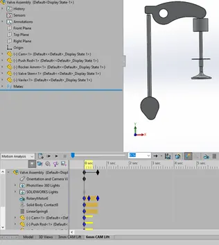
Fig – 3.1
Step 1 – We need to select Motion Study and Motion Analysis as shown in Fig – 3.1 and then tap on the icon which is shown in the figure. (Solidworks motion and Select Motion Analysis)
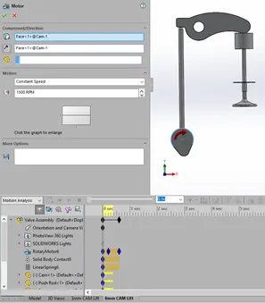
Fig – 3.2
Step 2 – We need to apply a Motor to CAM entering value of 1500 RPM as shown in Fig – 3.2.
Step 3 – In order to run the Motion Study successfully, we need to apply contacts as shown below.
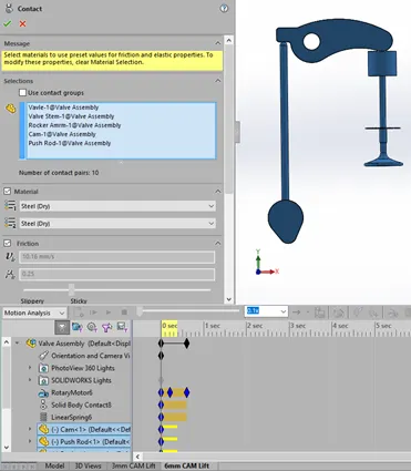
Fig – 3.3
Step 4 – We need to select all the bodies which comes in contact with each other through which the power is being transmitted. Observe Fig – 3.3 we can either select individual part or just click and drag out the mouse icon selecting whole part, this will allow us to give all the contacts in a single run.
Now follow the same thing for Case 2 which is 3.5 mm lift.
After this Results for both Cases are discussed below.
For given tasks we have performed the following –
4.1 Results for Case 1 and Case 2 –
- Valve Lift
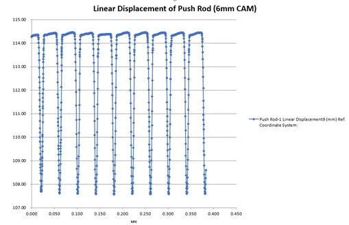
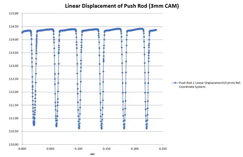
Fig – 4.1
Above plot for both Cases forms a Uniform and Smooth waves, this is due to the uniform displacement of the Push Rod (up and down), from the graph it can be observed that it is near about equal to CAM lift i.e. 6mm and 3.5mm respective to the Cases (this is nothing but the difference between higher and lower values from the Plot itself). Now if we will take a look at the Valve, it will displace more than 6mm or 3.5mm (Respectively to the Study), the reason of which, is because of Lever effect, now the reason why it will be more is because of the PIVOT point of the Rocker Arm is not at the centre, it is closer to Push Rod, meaning that when Push Rod travels some distance, then the Valve (w.r.t Push Rod) will travel more.
- Contact Force Between CAM and Push Rod
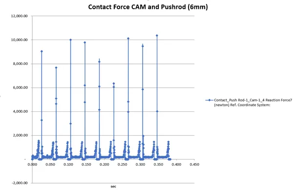
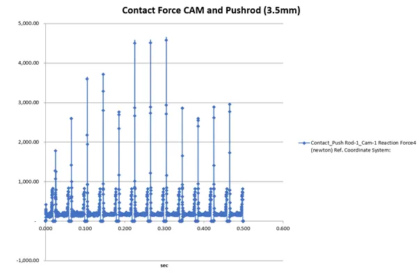
Fig 4.2
- Contact Force Between Push Rod and Rocker Arm
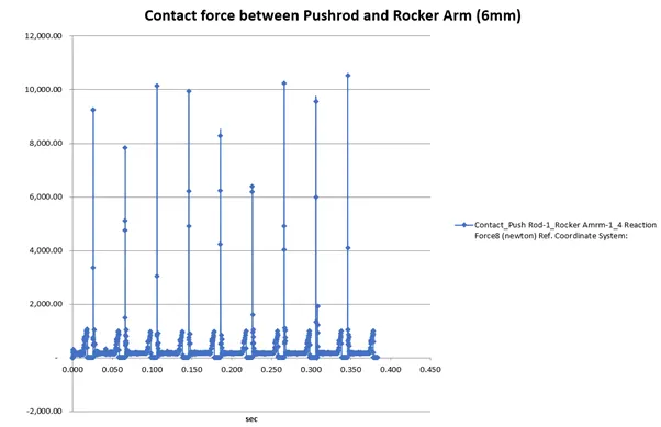
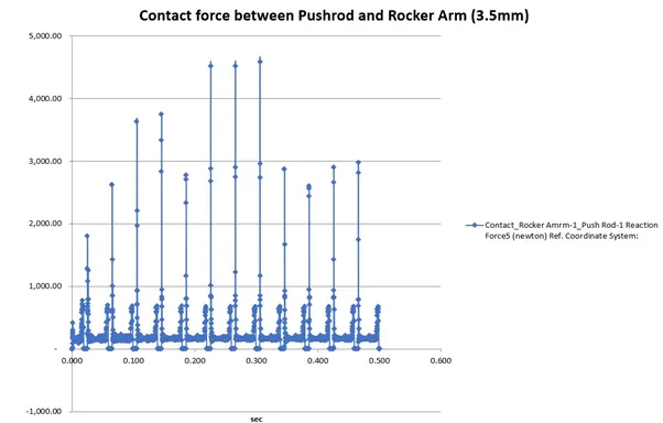
Fig 4.3
- Contact Force between Rocker Arm and Valve
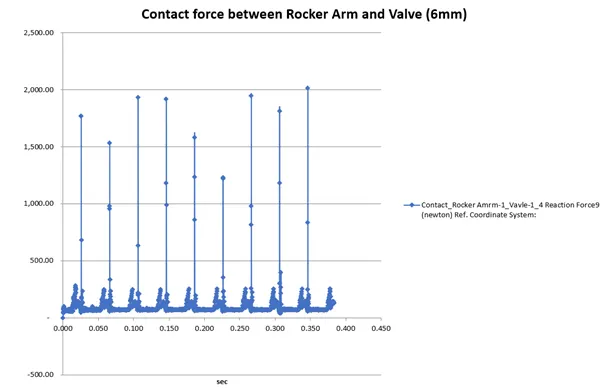
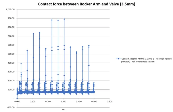
Fig 4.4
Above all cases for Reaction force shows that it is higher in case of 6mm CAM w.r.t 3.5mm CAM, which is normal
Link for CAD files is given below -
https://drive.google.com/drive/folders/1b9_xkdhlWY1gIGP2tGh5b2XOqTr9zsEN?usp=sharing