Comparing the performance of three types of beams under bending load.
Aim :- Finite Element Analysis and comparison of 3 different beams Plate under bending load using Solidworks.
Introduction:-
A beam is a structural element that primarily resists loads applied laterally to the beam's axis. Its mode of deflection is primarily by bending. The loads applied to the beam result in reaction forces at the beam's support points. The total effect of all the forces acting on the beam is to produce shear forces and bending moments within the beam, which in turn induce internal stresses, strains, and deflections of the beam. Beams are characterized by their manner of support, profile (shape of cross-section), equilibrium conditions, length, and material.
Classification of beams:-
In engineering, beams are of several types:
- Simply supported – a beam supported on the ends which are free to rotate and have no moment resistance.
- Fixed – a beam supported on both ends and restrained from rotation.
- Over hanging – a simple beam extending beyond its support on one end.
- Double overhanging – a simple beam with both ends extending beyond its supports on both ends.
- Continuous – a beam extending over more than two supports.
- Cantilever – a projecting beam fixed only at one end.
- Trussed – a beam strengthened by adding a cable or rod to form a truss
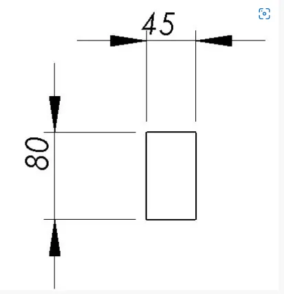
Case1:-
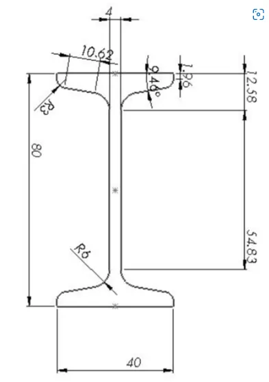
Case2:-
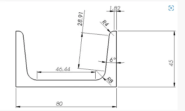
Case3:-
Theory on Simulation:
The bending of beams is modeled in Solidworks
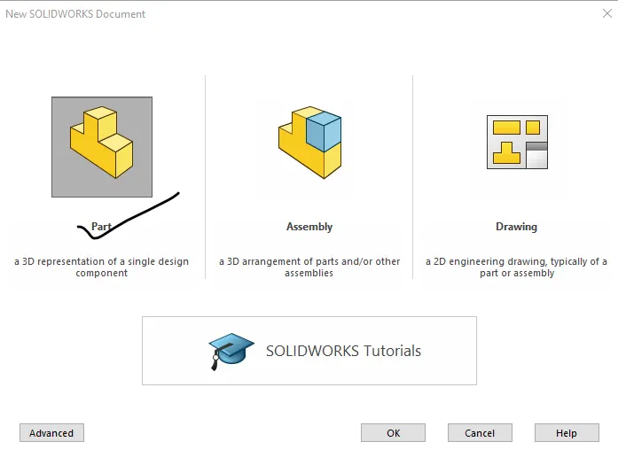
Initital sketch is done from opening new file part file
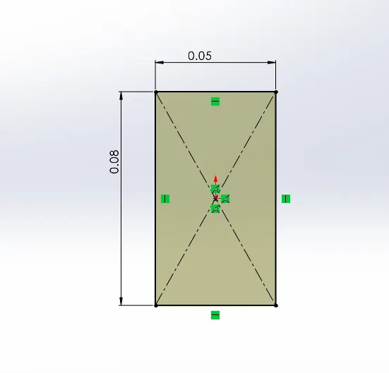
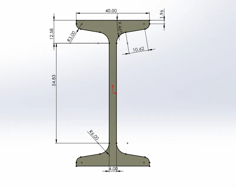
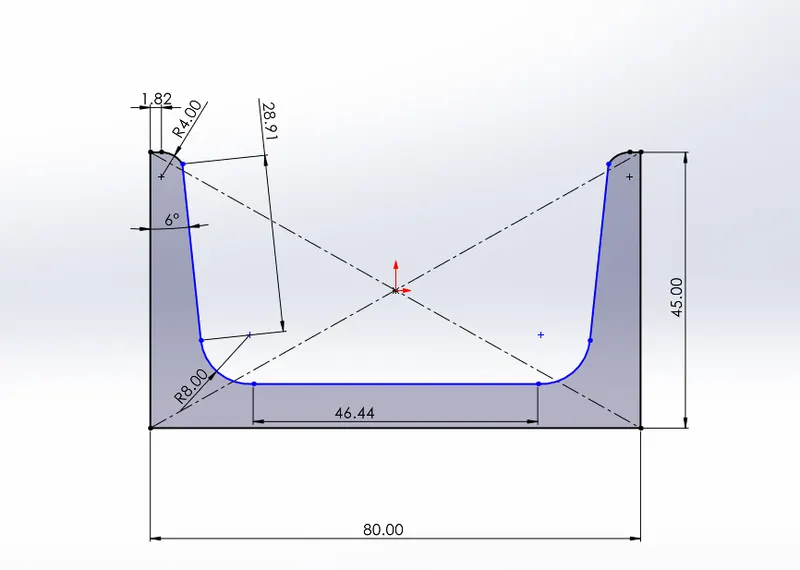
The model is sketched for cross section first from Rectangle

Case1:
Case2:
Case3:
Exit sketch and extuding the sketched surface by 400mm

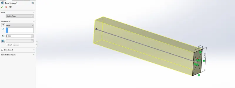
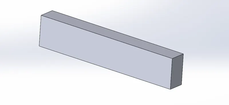
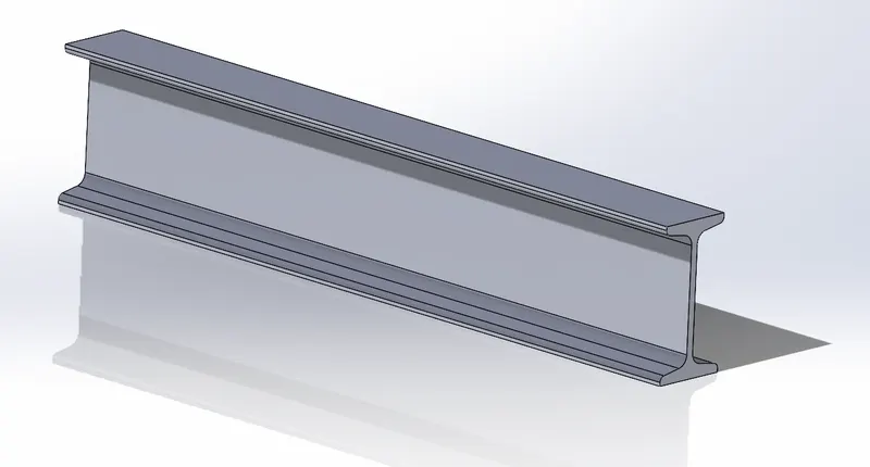
Similar to Case 1, Case 2 and Case 3 are modeled
Case2 Part:
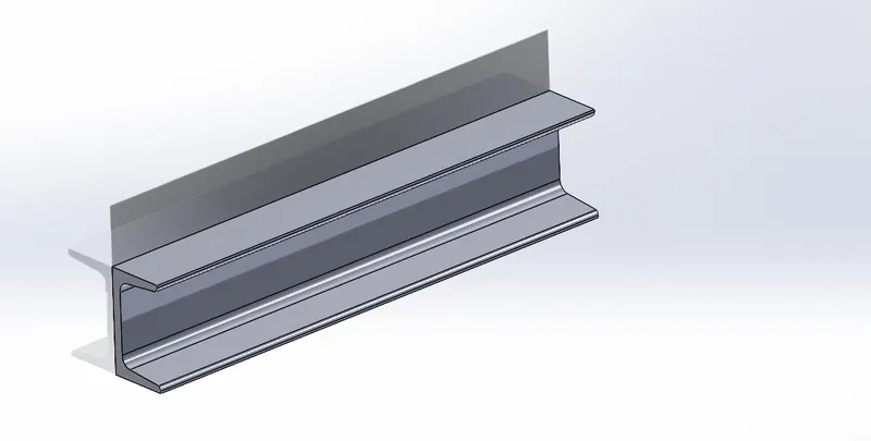
Case3 Part:
For starting the Simulation we go for new study under simulation tab

Since this is Static simulation, where load constant with time.
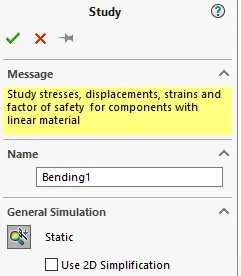
After setting the simulation study, the material is assigned to the parts as Alloy Steel
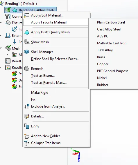
Then Fixtures are added to fix the geometry at one end and force apllied:
Case1:
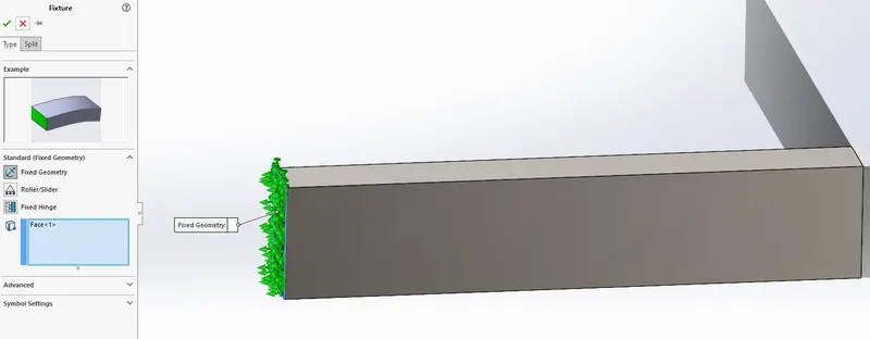
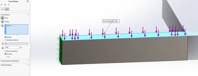
Case2:
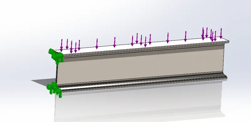
Case3:
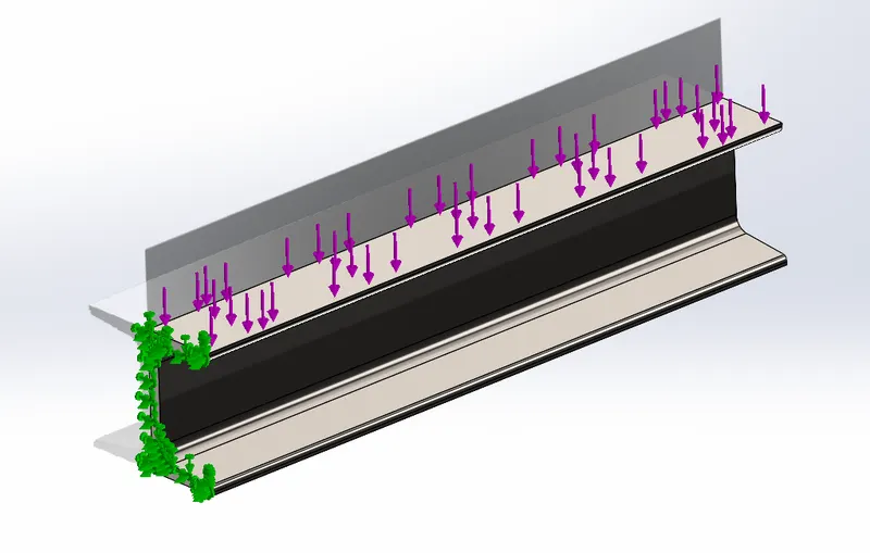
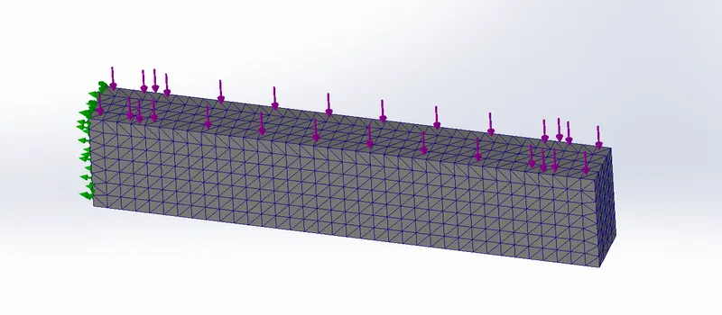
After application of boundary conditions mesh is defined for the components,
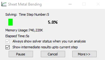
Then the solution is run using

Results:
The stress plot with showing yield stress is shown
Case1:
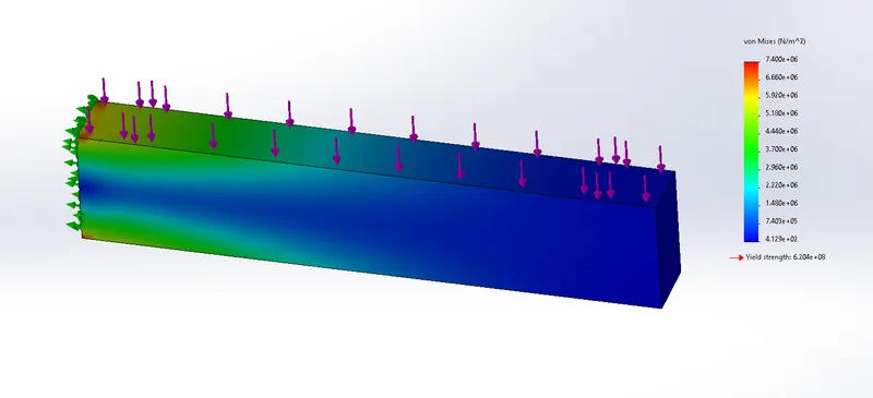
Case2:
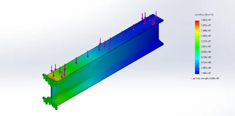
Case3:
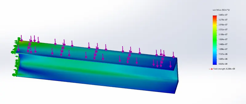
Froom Stress Plots we can see that the beam with case3 profile has maximum stress and case1 profile has min stress under bending load.
Displacement Plot:-
Case1:

Case2:
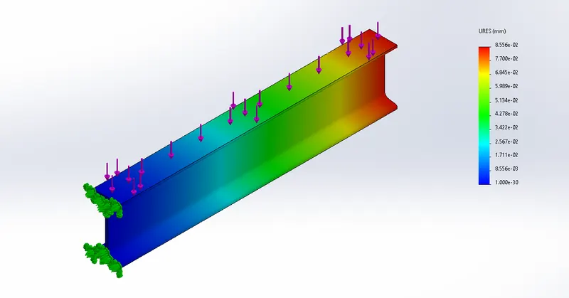
Case3:
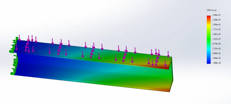
From Displacement Plots we can see that the beam with case3 profile has maximum Displacement and case1 profile has min Displacement under bending load.
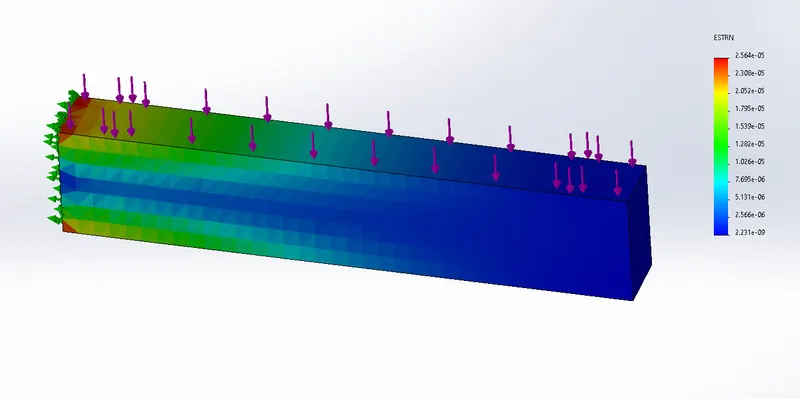
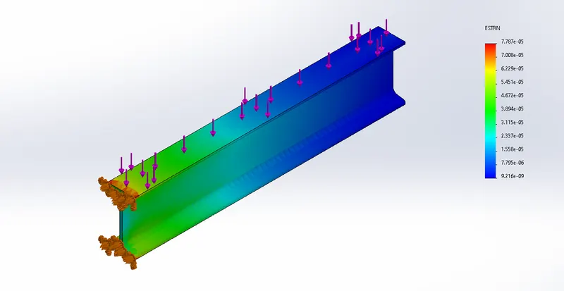
Strain Plot:-
Case1:
Case2:
Case3:
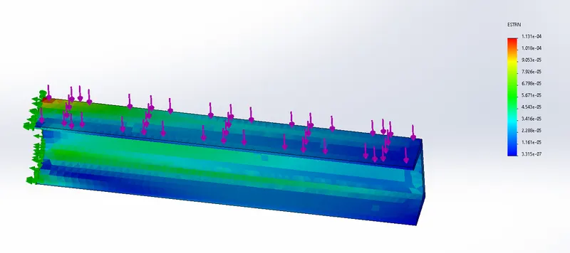
From Strain Plots we can see that the beam with case3 profile has maximum Strain and case1 profile has min Strain under bending load.
Conclusion:-
The Finite Element Analysis is perfomed and compared for 3 different beams under bending load using Solidworks.