Challenge 2
Ans 1
Components of Bridge
The various parts and components of a bridge are as follows:
- Deck
- Superstructure
- Substructure
- Foundation
- Girder or beam
- Bridge tower
- Pier
- Pier cap
- Bearings
- Piles
- Pile cap
- Bridge anchor
- Suspension cable
Let us learn each component of a bridge in detail below.
1. Deck
Deck is the portion that carries all the traffic.
2. Superstructure
The portion supports the deck slab and girder and connects one sub-structure to the other. That means all the elements of the bridge attached to a supporting system can be categorized as superstructure.
3. Sub-structure
The parts of the bridge which support the superstructure and transmit all the structural loads of the bridge to the foundations. For example, piers, abutments, etc.
4. Foundation
Foundation is the portion that transmits loads to the bearing strata. Foundation is required to support the piers, bridge towers, and portal frames. Generally, piles and well foundations such as H-pile bore piles, pipe piles, or precast concrete piles are adopted.
5. Girder or Beam
The beam or girder is the part of the superstructure which bends along the span. The deck is supported by beams.
6. Bridge Tower
It is the vertical supporting part used for cable-stayed or suspension bridges. High-strength concrete and In situ method are adopted to construct the bridge tower.
7. Pier
Pier is the part of the substructure that supports the superstructure and transfers loads of superstructure to the foundations. Pier (without cap) is suitable for spanned bridges with a maximum width of deck up to 8 m (2 traffic lanes).
The shape and size of the pier mainly depend on aesthetics, site, space, and economic constraints of the construction. Usually, bridge pier is constructed by in situ method with large panel formwork.
8. Pier Cap
Pier cap is the topmost part of a pier that transfers loads from the superstructure to the pier. It is also known as headstock. It provides sufficient seating for the girders and distributes the loads from the bearings to the piers.
9. Bearings
Bearing is a device which supports the parts of superstructure and transfers loads and movements from the deck to the substructure and foundation.
The main purpose of providing a bearing is to permit controlled movement and decrease the stress involved.
10. Pile & Pile Cap
Pile is a slender member driven into the surrounding soil to resist the loads. Pile cap is a thick reinforced concrete slab cast on top of the group piles to distribute loads.
11. Bridge Anchor
Bridge anchor is only used in suspension and cable-stayed bridges to resist the pull from suspension cable or counter span of the bridge.
12. Suspension Cable
It is used in suspension and cable-stayed bridges for the hanging, supporting and counter balancing of the bridge deck.
Ans 2
Super Imposed Dead Load (SIDL): Superimposed dead loads include all the weights of materials on the structure that are not structural elements but are permanent. It includes weight of track form plinth / rails / fasteners / cables / parapet / hand-rail / OHE mast / cable trough / signaling equipment etc.
For metro viaduct bridge footpath loading, permanent utility and track loads are most important.
Ans 3
Following girders may be used in metro viaduct:
- I Girder
Concrete - Precast, Pre stressed, Reinforced
Steel rolled, plate
- U Girder
Concrete - Precast, Pre stressed, Reinforced
T Girder
Concrete - Precast, Pre stressed, Reinforced
Box Girder
Concrete - Precast, Pre stressed, Reinforced
Ans 4
1. Elastomeric bearings
Elastomeric bearings offer a number of advantages:
1.Minimum maintenance- as no moving parts
2.Installation is easy
3.Permits movement in all directions
4.Occupies small space
5.Serves as a shock absorber due to anti-vibrations properties of elastomer
Factors Affecting Performance of Elastomeric Bearings :
Correct function of elastomeric bearing requires sufficient vertical load to prevent creep / slip and sufficiently high vertical deformation under normal loading to ensure that rotation of deck does not result separation between bearing and mating surface of the structure.
Elastomeric bearings are not advisable, if they are required to undergo simultaneously light loading and considerable longitudinal movement. This would apply, for example, to steel rail bridges with short and medium spans.
Elastomeric bearings do not distribute the vertical loads uniformly over the contact surface. Pressure at centre cans be as high as 1.5 to 2 times the average pressure. This should be kept in mind while designing the bed block.
To account for increase of rigidity (shear modulus) of bearing due to ageing and low temperature, it is recommended to increase the stiffness of bearing by 50% in design of substructures and foundation (UIC 772-2R).
However, while calculating interaction effects due to presence of LWR the analysis should be performed for both extreme values.
2. POT cum P.T.F.E. Bearings:
The structural rotations are facilitated by elastomeric pad, which responds with high vertical stiffness and low rotational resistance.
The sliding at the free ends is provided by stainless steel surface sliding over PTFE surface.
Slide guides provide restraint in the desired direction.
The coefficient of friction in these bearings is quite low - at par with the friction in rollers.
These are highly efficient bearings with minimum moving parts.
These bearings can safely accommodate 0.01rad. rotation about any axis. Normally Pot bearings are designed to bear pressure of 60 MPa at ULS and to allow rotation of 0.03 rad.
These bearings are more durable and more costlier. They can only be provided when elastomeric bearings cannot be provided.
3. ROCKER & ROLLER BEARING
Rocker and Roller bearings:
- Required in longer spans ( 30.5 m or more ) to cater for larger displacements
- Lateral movements are prevented by guides/ sleeves in different components. However, lateral clearances between moving parts of bearing are sufficient to meet requirement of lateral expansion for railway bridges.
- Rollers are Forged steel of Class-3 as per IS:2004. USFD test is conducted to ensure there are no internal flaws in rollers.
Ans 5
Following things should be consider for fixing height of metro viaduct when crosses water passage
1. Highest flood level.
2. Lowest bed level with locatn.
3.Height of boats ships for vertical clearance.
4.Overhead verticle cables to fix FRL.
Ans 6
Precast pre stressed I girder – As the shape is as I, it is known as I girder commonly used in metro rail. Designer checks the span length and design accordingly.
Precast pre stressed box girder – Closed web structure behaves very well in torsion loading in which shear due to torsion covers the larger area.
Small segment precast pre stressed box girder – Box girder in small part (3m) is assembled for long span (30-40m) is used for water passageway or traffic passageway.
Precast pre stressed U girder - Open web structure behaves very well in torsion loading in which shear due to torsion covers the larger area. Parapets are included in the girder and carries load.
Ans 7
Metro designer's choice is U girders because it is precast, prestressed and Open web structure behaves very well in torsion loading in which shear due to torsion covers the larger area. Parapets are included in the girder and carries load. This is light in weight. This is economical.
Ans 8
The structure which are open from top and webs are not connected to slab is known as open web structure.
Following advantages are:
- Single piece for a span.
- Time saving as precast in yard and launched by gantry.
- Construction is possible with running traffic conditions.
- Weight is less than other girder.
- Economical than other girder arrangements.
Ans 9
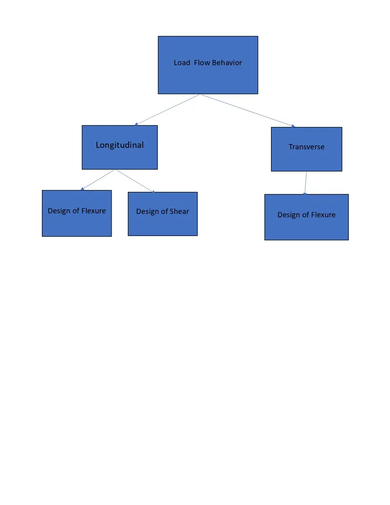
- In a open web girder arrangement it is saucer type girder which can be bend in bothdirections longitudinal and transverse, which means perpendicular to the movement of the trains.
- The structure needs to be designthis open girder in saucer like bending which means it has to be designed for longitudinal bending and transverse bending.
- In longitudinal bending it should be designed for flexure and for shear. And in transverse direction have to design it for flexure because the shear effects in shorter span is negligible.
Ans 10
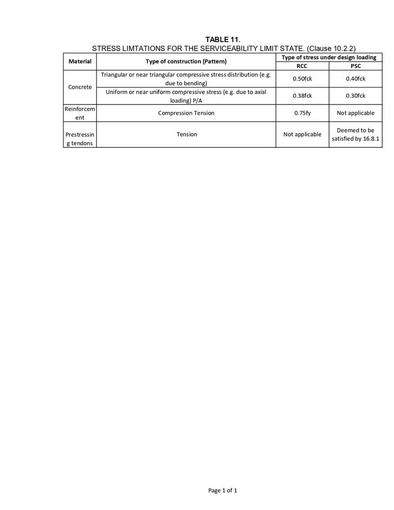
For reinforced concrete and prestressed concrete the compressive and tensile stress limitations are
Ans 11