Challenge 2
Aim:
Need to explain the structural components present in the typical bridge and to explain in detail about the components and their functions involved in the system.
Introduction & Explanation:
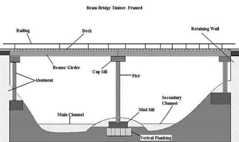
Bridge system involves substructure and superstructure components. Under each component number of elements involved to do its function perfectly. Following are the components under superstructure:
- Parapet/Railings
- Girders
Following are the components involved in substructure components:
- Bearings,
- Pier cap
- Abutments/wing walls
- Pier
- Foundation
- Parapet/Railings
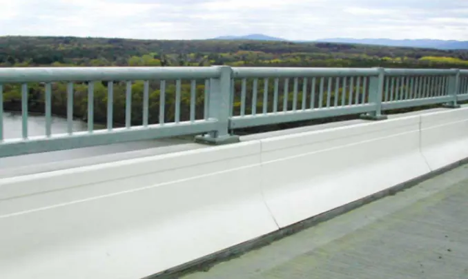
- These are the components present over deck/girders that act as a safety measure to the people using bridges.
- From a design point of view, it will be considered as a sustained dead load, and it won’t contribute to any structural integration in the system.
- The material used: concrete, steel & polycarbonate.
- Deck & Girders
- In the highway bridge system, the deck will be acting as a slab under the girder that will distribute the load to the pier cap & piers.
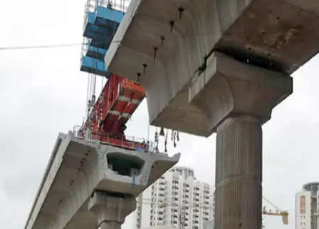
- But in metro viaducts, I-shaped girders, box type girders, U-shaped girders, steel box type girders are used.
- The material used: concrete & steel.
- From a design point of view, it will be considered as self-weight and it involves the structural integrity of the system.
- Girders used in metro viaduct construction contain cables & cable trays that will be considered as sustained dead load in the analysis.
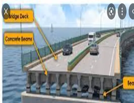
- Bearings
- Bearings are the material that restraint the movement of the girders due to the action of seismic & vehicle movement
- The material used: Elastomeric bearings, POT PTFE Bearings.
- The elastomeric bearing will be used when:
- Span range between 25m to 28m
- Need to go cost-effectively.
- Needs to be easily replaced due to wear & tear.
- POT PTFE bearings will be used when:
- Span range more than 28m.
- Need of more durability
- Go for costlier material.
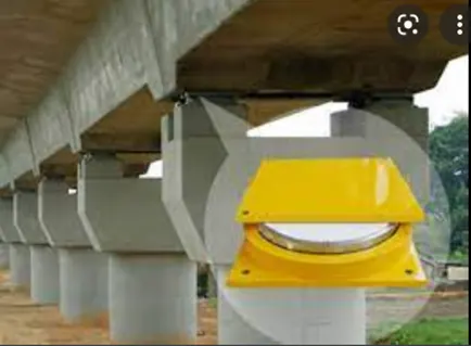
- Pier cap
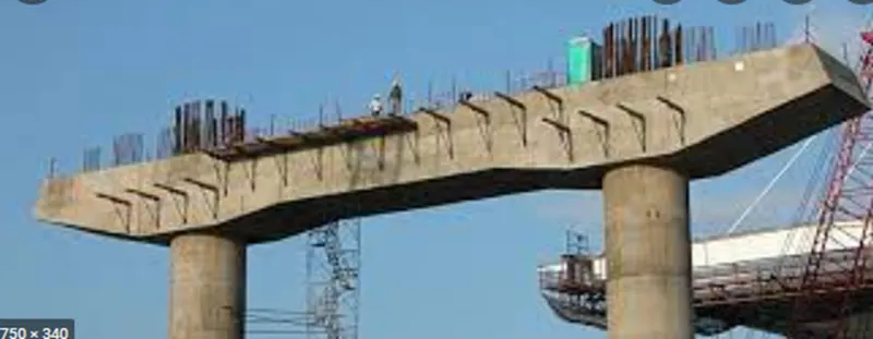
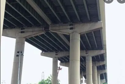
- Pier cap is an element present over the pier to collect the load from the girder and transfer it to the pier.
- Pier cap may be RCC/Prestressed depending on the requirement.
- It has different shapes and still, the architects were working on the shapes to add a more aesthetic appearance to it.
- Sufficient dimension of the pier cap to be planned to accommodate the bearings, shear keys, etc.
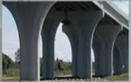
- Pier
- It is a structural member that transfers the load from the superstructure to the substructure.
- It involves the structural integrity of the analysis.
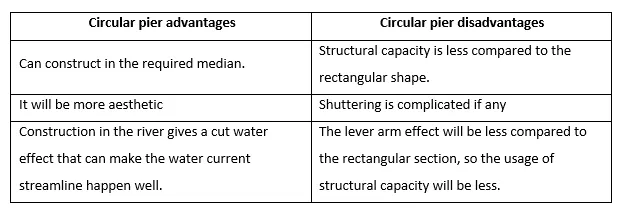
- It may be a rectangular, circle, or if any depending on the requirements.
- Foundation
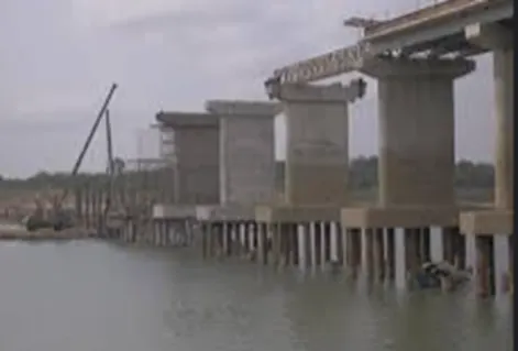
- Mostly used foundation system will be the deep foundation – pile foundation.
- Here different shapes of pile systems will be arranged depending on the utilities provided.
- Additional points
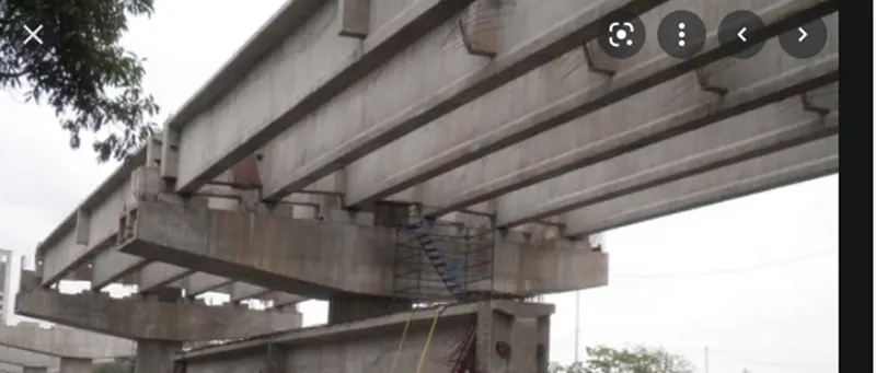
- PSC I Girder
- Depending on the height used, the construction sequence is to be planned.
- Pier height decision to be fixed based on High flood level, cable laying heights, etc.
- The flange portion in the I girder will be having more width due to the position of strands and this portion was placed away from the neutral axis so that structural capacity will be used more.
- It can be used in the span range of 26m to a max of 33m.
- It can’t be able to handle torsional loading if more than 33m.
- PSC I Girder
- Box Girder
- From the name itself, it will be giving box effect / closed effect.
- Due to the closed section effect, behaved well under torsional loading.
- Because of the closed effect, it will be having a more cross-sectional area for the torsional shear flow effect along the periphery.
- This type of cross-section is used to reduce the dead weight of the structure.
- Due to the self-weight reduction, segmental construction can be adopted.
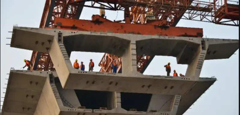
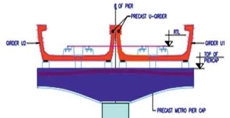
- U Girder
- Most often used cross-section in metro construction.
- Due to its lower rail levels, it comes under the economy category, reduction in stair height level, reduction in pier height, etc.
- Sides of U girder acts as a parapet also involve the structural integrity of the analysis.
- The sides of the U girder will act as a noise barrier.
- It is easy to construct & erect.
- It can’t be able to take higher torsional loads.
- Up to 30m, it will act for torsional loads.
- Due to its less weight and low thickness, can make a slender section.
- It attracts more seismic loads in the foundation due to its being less self-weight.
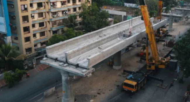
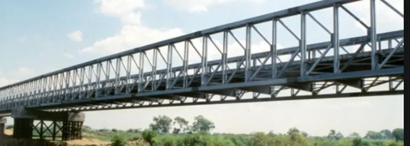
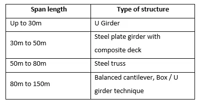
- Steel structure
- This type of structure will be used if the span range is between 50m to 60m.
- It is having the combination of the I section with composite concrete deck.
- Steel box girders were also used.
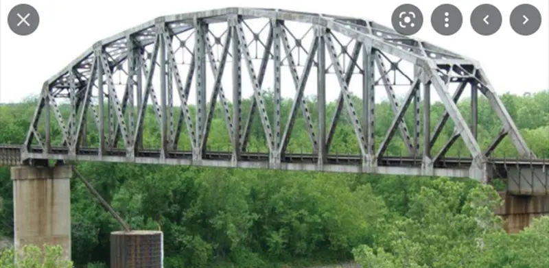
- Truss structure
- This type of structure will be used if the span ranges between 60m to 80m.
- Additional points
- Depends on the type of structure, span length to be finalized and the type of structural construction to be chosen.
- Tested technology and tested construction methods to be followed.
- Points to be considered in the design of U-girders:
- Will be considered as a good shape for metro viaducts.
- Having sufficient space inside the viaduct for placing the rails.
- It will be named C-shape/U-shape.
- Due to its ample space inside the viaduct, placing accessories & cables will be easy.
- The size of the coach decides passenger size volume.
- Kinematic envelope (boundaries to which the metro moves within the viaduct) will be attained.
- The bottom width should be sufficient to accommodate the rail of full gauge.
- The bearing will be placed outside the girders to remove the cantilever effect.
- The elastomeric bearing type will be commonly used for economic purposes.
- Drainpipe at the base slab between the bearings to take all the wastewater to the drain.
- The thickness of the slab is restricted to 240mm due to design considerations.
- A shear key inside the base slab of the drainpipe is given to restrain the transverse movement of the spanned element. Also, it restrains the shifting of longitudinal and transverse viaducts.
- An expansion joint of 25mm thickness will be used.
- For the open web structure, the frequent span range used will be 25m to 28m.
- While fixing the span, the economy of construction cost is also to be considered.
- Due to maintenance of bearing at every 5 years to 10 years.
- It is to ensure that prestressing stands to be accommodating to the section provided.
- This section is a non-symmetric section due to the consideration of walkway provisions.