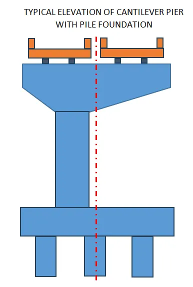
Challenge 10
1. The dimensioning and sizing of the pile cap shall be done with consideration of the construction tolerances of the piles. These construction tolerances can be less for ground based piles and more for river or sea based piles. The edge of the pile cap shall be generally 150mm farther from the edge of the pile to accomodate the tilt and shift of piles. This distance may vary upto 200mm or more when higher tilt and shifts are anticipated in deep piles in sea or river locations. In terms of design considerations the bending moments in pile may vary in pile cap due to variations in locations of piles which may result into increase in lever are for moments due to vertical loads from pile. This is generally not critical but can be critical for piles with large tilt and shifts.
2. Following are the loads and load combinations to be considered at the bottom of the pile cap for design purpose:
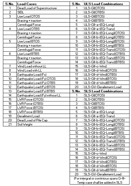
3. There are various loads which are exerted on the pile cap. These are of various types such as dead load, SIDL, live load, vehicle collision load, derailment load, wind load etc. Some of the loads are coming from portion of the structure above the pile cap top and some are from the pile cap itself like self weight of pile cap. It is important to consider the proper values and lever arms for these loads while working on the rivet theory for calculation of pile forces which are inputs for shear and flexure design of pile cap.
For working on rivet theory we shall consider the forces and moments at the pile cap bottom level. In this the lever arm equal to depth of pile cap gets added to the moments coming from pier. After completing the pile force calculations for all the combinations, these loads are applied as external forces applied on pile cap. While calculating the resultant moments on pile cap sections for flexure design and stress checks it is important to reduce the moments due to selfweight of the pile cap, weight of pier protection above pile cap to get correct values for pile cap design.
It is important to consider maximun and minimum working loads for force calculations in piles since the vertical loads from the both span loaded condition may not be critical for pier as it does not cause any moment but this case can result into maximum forces in the piles which may lead to maximum bending moment in pile cap. This is because moment in pile cap is vertical force in pile x distance of pile from pier face.
When only one span is erected or in case of one span dislodged condition, the vertical force in the pier are low but there is considerable amout of moment. This may result into tension in pile and this lead to tension at the top of pile cap which needs to be checked and designed accordingly.
4. The clause 15.4.2.2 of IRS Concrete Bridge Code gives the simple formulae for calulation of bending moment capacity of typical concrete section. These formulae are function of key inputs such as grade of concrete, grade of steel, area of reinforcement and depth of section. This can be used for calculation of reinforcement of pile cap.
The clause 15.9.8.2.1 of IRS Concrete Bridge Code gives simple formula for calulcation of crack widht of a rectangular section. This formula is gives the crack widht with consideration of tension stiffenning effect of concrete. The inputs for this formula are strain in concrete and strain in steel from our basis formula, depth of section, spacing of bars. This simple formulation can be used for crack width check of pile cap section.
5. Pile caps are the structural elements which transfer the load from pier to piles. These are heavy and robust elements which transfer the moments in pier as axial forces (Push & Pull Effect) in the piles.
Pile caps have following 3 significant functions:
a. It acts as a structural element to transfer the vertical force horizontal force and moments from pier to piles
b. It also accomodate the construction tolerances in the piles which occur due to tilt and shift of piles during construction.
c. It also acts as a supporting for pier shuttering and pier construction activities
Additionally, piles caps also provide stability to the pile group system even after scouring of bed material surrounding top piles. It also reduces the chances of differential settlements.
The types of pile foundations are - Concrete Piles, Steel Piles, Group piles, Monopiles, Raker Piles, Cast-in-situ piles, driven piles, Under-reamed piles
6. Monopiles are a pile foundation in which only one pile is driven in order to support a single pier. Hence there are no group of piles supporting the pier. These piles are generally larger in diameter as compared to group pile since all the loads from pier go to these piles in form of vertical loads and moments.
Monopiles are preferred in following situations:
a. When the speed of construction required is very high. The monopiles are fast in construction as we need to construct only one pile at one pier location.
b. They are generally used in 25m to 30m depth and in sea conditions where time of construction in challenging weather conditions is very less for monopiles as compared to group piles
c. It can also be adopted in areas congested due to utilities where group of piles may not be feasbile.
7. Orientation of Piles in a group of piles is a key aspect in design of pile. A rough estimate of vertical loads and lateral load provide the tentative number for piles required in the pile group. This is generally based on the vertical capacity and lateral capacity of individual pile.
If we increase the spacing of piles then the axial forces in the piles get reduced. However this increase the lever arm of pile from pier face and shall result in increase in pile cap moment.
The spacing of piles in generally kept from 2D to 4D. When piles are spaced at lesser intervals then pile cap design is economical due to strut and tie action / reduced lever arm of piles. But this also results in increased axial forces in piles. Hence it is important to space the piles appropriately based on the moments in longitudinal and transverse direction coming from pier.
Orientation of piles can also be kept eccetric to neutralise the permanent differential moments which are generally there in case of unequal adjacent spans or span with different materail on either sides. This can economise the substructure design.
In case of cantilever piers also the C/L of track or superstructure can be matched or brought close to the c.g. of pile group to reduce the moment due to permanent loads.