Cell balancing of Lithium-Ion 4 cell Battery
Aim : To balance battery Lithium-Ion battery cell and compare IGBT and MOSFET switch output.
Answer :
- Here you can see three subsystems in which one is for battery, second for control and last one is scope output.
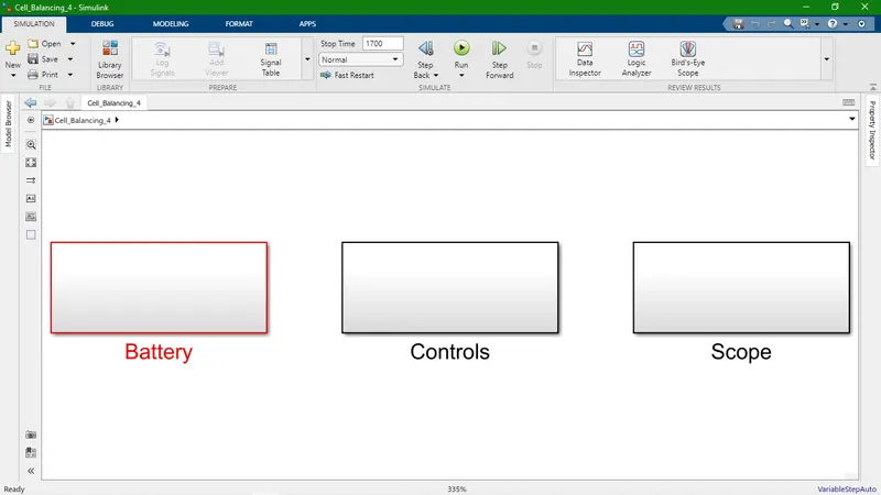
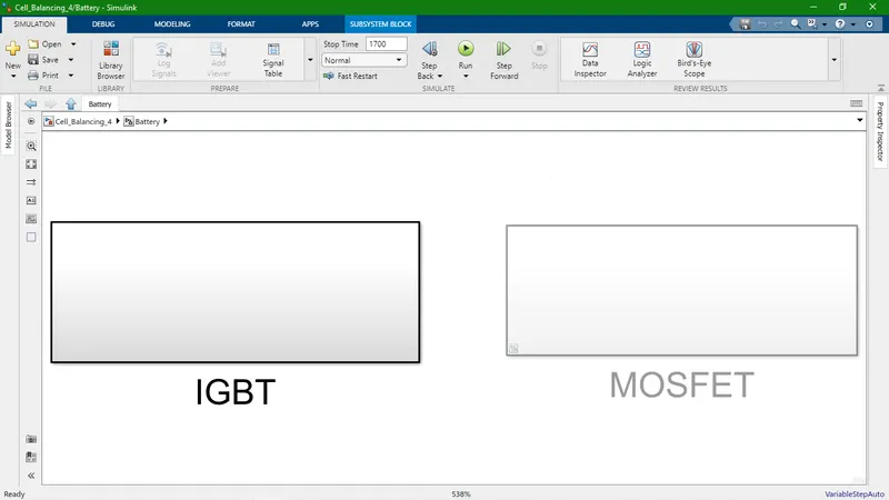
- Battery have two subsystem - here choose one out of two for further simulation.
- In IGBT subsystem :- As a switch used insulated-gate bipolar transistor.
- In MOSFET subsystem :- As a switch used metal-oxide-semiconductor field-effect transistor.
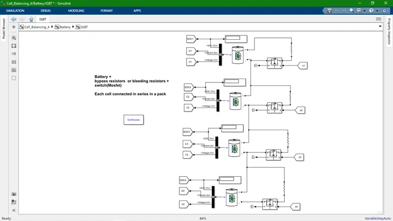
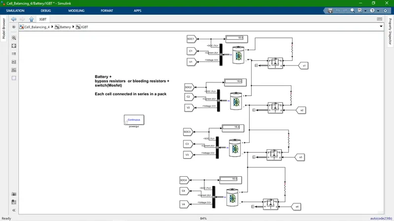
- This is IGBT subsystem.
- it's main components are Generic Battery, IGBT switch, Bypass resistor (RLC).
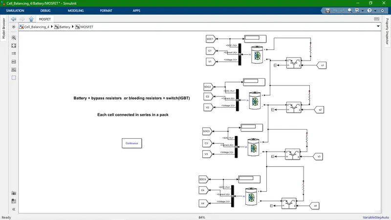
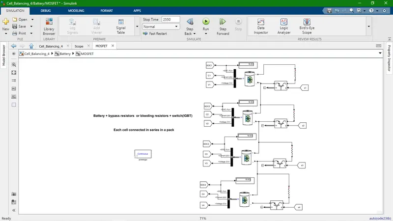
- This is MOSFET subsystem.
- it's main components are Generic Battery, MOSFET switch, Bypass resistor (RLC).
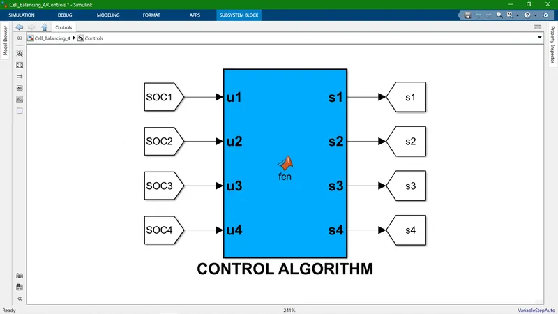
- This is the control algorithm subsystem with function block.
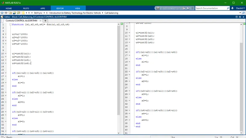
- This is a code for control algorithm.
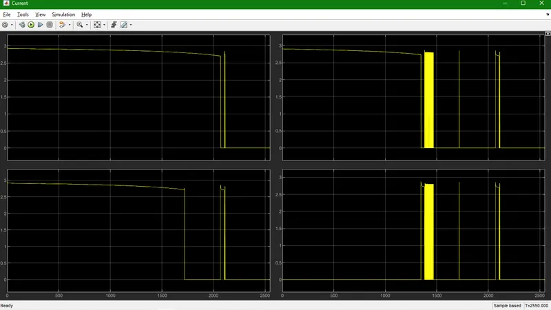
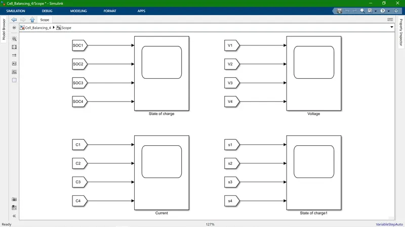
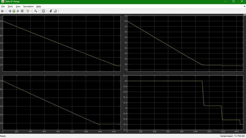
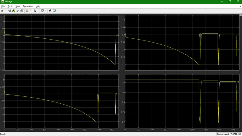
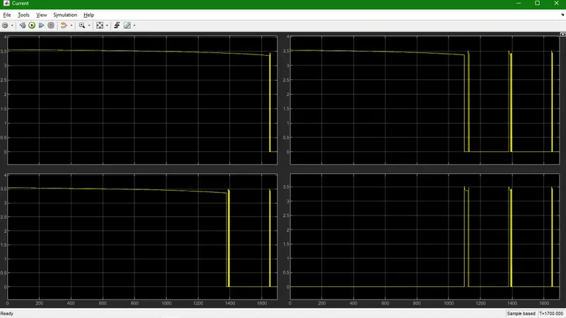
- Output of simulation like SOC, Current, Voltage.
- Here, Display box give information about battery SOC level all have same value it mean battery cells are balanced.
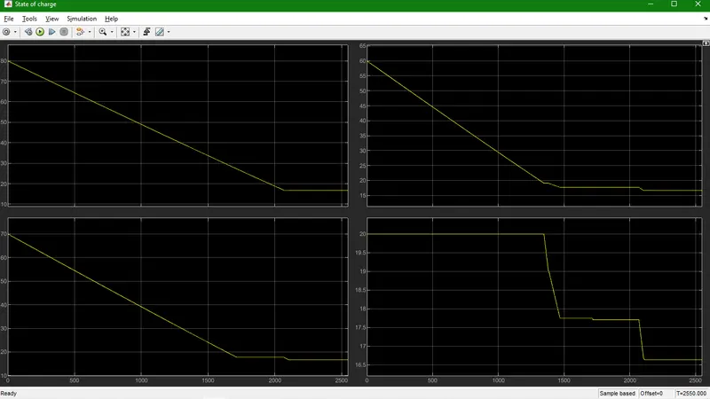
- This is Output of Individual cell SOC(State of charge).
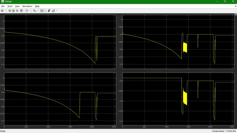
- This is Output of Individual cell voltage.
- This is Output of Individual cell Current.
- Here, Display box give information about battery SOC level all have same value it mean battery cells are balanced.
- This is Output of Individual cell SOC(State of charge).
- This is Output of Individual cell voltage.
- This is Output of Individual cell Current.