Cell Balancing Management using MATLAB Simulink
1. Introduction:
Battery Management System is one of the important components in an Electric Vehicle. EVs have many advantages over conventional cars such as the IC engine based cars such as efficiency, a high energy density, good acceleration, less pollution, and more. But batteries have a major challenge to overcome, which is the long charging time and damages caused to the battery over time.
EVs use battery packs with hundreds of battery cells linked in a series or parallel configuration to meet high power and voltage demands, which produces a complex battery system. Improper battery conditions such as over-current, over-voltage, over-charging, and over-discharging cause battery damage and rapid aging, and above all, can lead to safety risks such as fire and explosion. A battery management system or BMS is required to improve battery efficiency and to provide protection for a battery for these reasons.
In order to describe internal battery conditions, the BMS includes sensors to calculate battery parameters (voltage, current, temperature) and the proper battery modeling and estimation methods. The charging and discharging algorithms need to be designed to provide maximum EV performance and the battery life after determining the electric and thermal behaviors of the battery. The alarm and safety control module is another essential part of the BMS, which has to record or remove any anomalies in the operation and condition of the battery.
The four main technologies in a BMS are:
- Battery modeling
- Internal state estimation
- Battery charging
- Alarm and safety control
The starting point of a BMS is developing the correct battery model. BMS parameters, such as voltage and current during the process of charging and discharging, depend on the operating conditions of the battery (the load, age, temperature, etc). Reliable data on the battery actions during the charging/discharging processes must be obtained, but it is not feasible to do so for actual battery activity under all operating conditions over the lifetime of the battery. Battery modeling thus uses a virtual battery mathematical model to check that the BMS can operate properly for the corresponding battery pack. Battery modeling describes a study of battery behavior, monitoring of the battery state, real-time controller design, diagnosis of faults, and thermal management.
2. Battery Charging:
When the voltage is lower than the cut-off voltage or when the charge state of the battery is below 20 percent, a battery is discharged. It is imperative to interrupt the discharge process at this stage and recharge the battery. Over-discharging and overcharging a battery will drastically affect its condition, as this greatly accelerates the deterioration of the battery.
It is an important part of the BMS to establish a proper method of battery charging. The approach is based on a reliable state of charge (SOC), state of health (SOH), and temperature battery estimates. The correct approach to battery charging enables effective battery charging from the initial to the final state of the SOC battery, as well as prevents the battery from overheating, extends its life cycle, and enhances the utilization of power.[1]
A dominant factor influencing battery charging efficiency is temperature. The life cycle of Li-ion batteries is shortened by high temperatures and charging is not recommended in conditions below freezing.
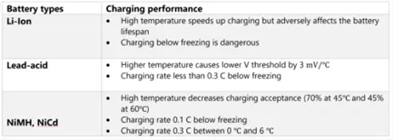
Table.1 Different Battery Performances
Traditional Battery Charging Methods:
The 4 popular and traditional charging methods:
- Constant Current (CC) Charging
- Constant-Voltage (CV) Charging
- Constant-Current-Constant-Voltage (CC-CV) Charging
- Multi-Stage Constant-Current (MCC) Charging
In this paper, we shall be evaluating the first two methods, as it is currently been used widely.
1. Design and Simulation of Constant Current Charging method:
Constant current charging uses a small constant current to charge the battery during the entire charging cycle. Fig. 1 is the design that we have created for the constant current process. This is the same circuit that will be used in Constant Voltage, but the only difference is the Control subsystem, which will be discussed later in the section.
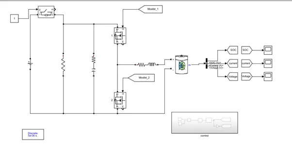
Fig.1 Simulink Model Of Constant Current Charging Method
The Battery used in this simulation is a 24V battery, and the DC voltage source is 48V, as the DC should be able to satisfy the power requirement for the battery after passing through resistors of the circuit. The Ideal switch, in this case, is closed, such that a constant current of 6A passes to the battery for charging. This Constant current does not change with varying voltage and SOC. The Battery in this design is being charged from 45% to 45.1% of SOC, as the initial SOC has been defined as 45%. Initially, the voltage rises from 24V to 25V and then increases from time to time. In this simulation, we can observe that a CC type charging can balance the cells arranged in a series connection. The charging current rate is the most important factor and it can significantly influence the battery’s behavior. So for this reason, I have set a current rate of 6amps. If the current rate is set for a higher value, it will significantly reduce the charging time and capacity utilization. But it might affect the battery’s aging process. In my case, a low charging current (6A) provides high capacity utilization but it took a lot of time from the state of charge 45% to 45.1%. Such low current rates are not recommended for EV users, as it would consume a lot of time. For this purpose, Constant Voltage is preferred, as it more rapid and less time-consuming.
The Ideal switch connects the DC voltage source to the battery, while there are two MOSFETs (Metal Oxide Semiconductor Field-effect Transistor) which functions on the electrical variations happening in the channel width along with the flow of carriers. MOSFETs in particular, function in 2 ways, depletion mode and enhancement mode. The channel demonstrates its full conductance when there is no voltage through the gate terminal. Whereas the voltage is either positive or negative around the gate terminal, the conductivity of the channel decreases. The system does not operate when there is no voltage across the gate terminal. The unit demonstrates improved conductivity when there is the highest voltage across the gate terminal.
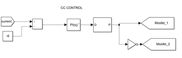
Fig.2 Control Subsystem of Constant charging method
Here the Positive node of the battery is connected to the battery charge current but the negative node is connected to the Reference current which is 6A in our case. It is keyed as -6, as the current is going to the battery and not coming out of the battery. The CC control comprises of the PI controller, unlike the PID controller, is a loop for feedback control that calculates an error signal by taking the difference between a system's output, which in this case is the battery's power, and the set point. Pulse Width Modulation, or PWM, is a technique for digitally obtaining analog data. A square wave, a signal switched between on and off, is generated by digital control. On and Off modulated the MOSFETs set in the actual circuit thus enabling the MOSFET to function in either depletion mode or enhancement mode.
2. Observations:
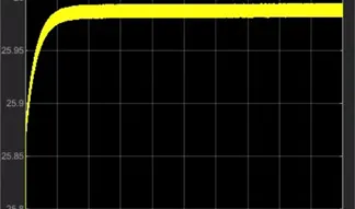
Fig.3a This result depicts the value of Voltage over time, as per this observation, the voltage increases from 24V to 26V over time.
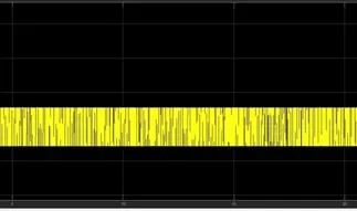
Fig. 3b This picture depicts the value of current over time, the constant current is 6A in this case
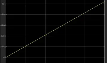
Fig. 3c This picture depicts the State of Charge from 45% to 45.1% over time.
3. Design and simulation of Constant volume charging methods
Constant volume charging methods is similar to the constant current charging method. Same POWERGUI with discrete time steps of 5e-6s and same battery specification. To find the maximum voltage of the battery we have to disconnect the battery and initializing the initial State of charge as 80 to 85%.by assuming the value of Soc and battery we can able to find the maximum voltage as shown in the figure the value of voltage is 25.66v.
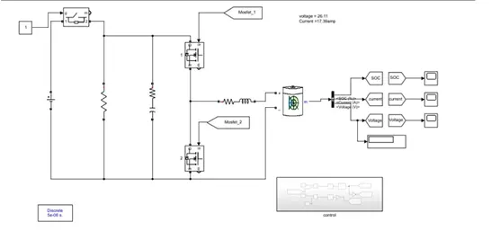
Fig.4 Simulink Model Of Constant Voltage Charging Method
The main component PID (proportional, Integral, and derivative) is to keep something constant we can use the PI controller. For instance, in an automotive vehicle after attains a certain speed limit we press cruise control so that the vehicle with ECU and speed sensor gets feedback every second and acts according to it. The upper limit and lower limit are assigned to set the level of current the battery takes. The maximum current will be 17.95amp and the next important component PWM is the pulse width modulation with (DC-DC) generator is it to change the duty cycle of the square wave pulses output by a PWM enables a digital output to provide a range of different power levels similar to that on analogy output. [2]
As we considered reference current in constant current as negative we must also consider negative in GAIN.
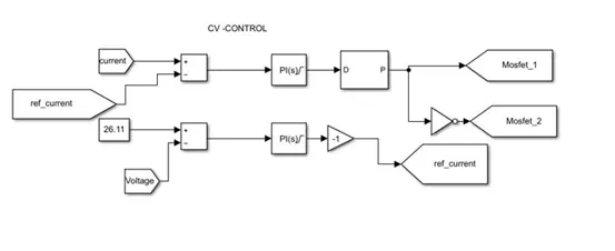
Fig.5 Subsystem of CV Control
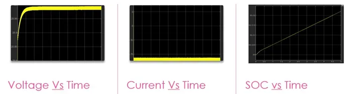
Fig.6 Resultant graphs
From the 3 recorded graphs
- From the voltage vs time graph we can notice that the once the voltage reaches to its maximum (25.66v) it remains constant along the time
- From the current vs time graph, the initial soc again changes to 40% so that we won’t commence current from ZERO. Once the Soc reaches 80% the current starts decreasing from its maximum of 17.35amp to 0 along the period of time.
3. The Need for Cell Balancing in a BMS:
Battery packs are made up of different cells in series in order to achieve higher operating voltages. From our previous observations, we can understand that CC and CV charging is accomplished on a certain number of cells. But in reality, we have to deal with a lot of cells in a battery. Due to the differences in aging, individual cells react differently to the charging process of CV and CC. This necessitates cell balancing, in order to prevent overcharging or overheating and also to ensure maximum efficiency.
During a cell cycle, the voltage distribution among the cells would not be equal since there are multiple cells in a battery and it could cause cell degeneration and also catch fire. Cell balancing or battery redistribution is a technique used to improve the capacity and longevity of the battery. It is usually done by placing various cells in series or parallel to help to increase the cell efficiency and would allow it to withstand for a longer period of time [4].
Cell balancing is the process of equalizing the voltages and state of charge between the cells. In a particular battery, there are no identical cells in it where lots of factors come into play such as state of charge, capacity, self-discharge rate, impedance even if the cell is of the same model. The process of combining the cells with approx. same voltages and due to this reason the cell diverges over time. In theory when a battery's maximum voltage is reached and no cell is overcharged it is said to be at maximum charge irrespective of the voltage levels in other cells. The weaker cells with high impedance and high capacity will have higher voltage and these will be weakened by continuous overcharged cycles. This also reduces the battery capacity
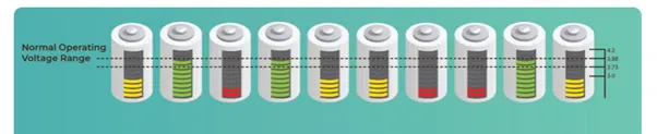
Fig 7 Various cell voltage distribution
In the first cell distribution, cell number 2 has reached its maximum voltage limit and overvoltage protection circuit is enabled and charging is disconnected while other cells haven’t reached their limit due to this the full utilization of the cells and cell number 3 reaches the under-voltage limit and full capacity of the battery cannot be used. These both can cause faster cell deterioration and reduces battery efficiency.
This can be rectified with help of BMS, it is to avoid overcharging the battery and undercharging the batteries. Cell balancing is done to equalize the voltage of the battery through the battery cells with help of various circuits it is also done to maximize the charging and discharging efficiency. [3]
4. Cell balancing techniques :
Various cell balancing techniques are employed to rectify this issue since various factors such as soc imbalance, internal resistance variation and temperature are different for each cell and it cannot be prevented to avoid imbalance. There are various types of techniques used.
- Passive Cell balancing
- Active cell balancing
- Lossless cell balancing
- Redox shuttle
But in our paper, we shall be reviewing Passive cell balancing and active cell balancing.
5. Passive Cell Balancing
In this type of cell balancing the additional voltage in the cells will be wasted or removed with help of a resistor. This helps to make the state of charge and voltage of each cell equal. This method wastes voltage and this is one of the main disadvantages of this type of cell balancing.
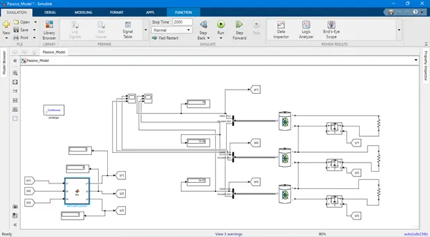
Fig.8 Passive Cell Balancing
1. Construction:
This can be done with N number of resistors depending on the number of cells and voltage. This Simulink circuit consists of three 12 volt and 2.6 Ah batteries which are connected in series. These batteries are connected to 3 resistors which are later connected to MOSFET. Three BUS connectors are placed on the left side of the battery in series with their input connected to the battery. These BUS connectors are set to SOC and current. Scopes and displays are connected to check the SOC.
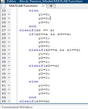
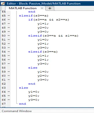
A Matlab function is installed with 3 inputs and 3 outputs with all the input connected to soc and output connected to the gate
2. Matlab Function code:
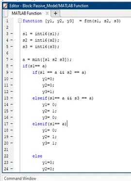
- For the models, Three inputs values S1, S2, S3, and three output valuesY1, Y2, Y3, are set.
- S= int16(S1);
- This code converts decimal values for SOC into integral values. For instance, 36.7 will be converted to 37. Not provide accurate results is the reason behind not using decimal values directly.
- a=min{( s1, s2, s3)}
- Here 'a' is defined as the variable which stores the minimum value when batteries' SOC are compared to each other, the lowest being stored in 'a'.
- if(S1==a);
- This function compares the cells. If S1 has the lowest value satisfying the condition, will get stored in 'a' or 'Elseif(S2==a)' will start running. If S2 also fails 'else (s3==a)' will come into action.
- Considering S1 to be a true condition, the nested loop will start acting.
- In the loop, until each cell matches the value of lowest, it Will continue to drain. Discharging of cells is controlled by MOSFET permitting only Stronger cells discharge. When the Value of Y=1, MOSFET will remain ON, The cell will continue draining. Until Y=0, which will turn off MOSFET
3. Result:
Maximum output has been achieved from this circuit with the cells being balanced perfectly. This is achieved by the trial and error method by simulating it with different seconds. This process was repeated until the optimal result was achieved where all the cells are balanced.
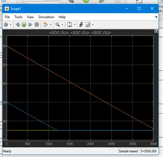
Fig.9 Passive Balancing Graph
As the graph indicates the SOC value of cell 1 and cell 2 were too high and imbalanced. After running the circuit the SOC value was balanced by removing the excess voltage with help of a resistor and the battery was balanced.
6. Active cell balancing
In passive cell balancing the main drawback was wasting the voltage with help of a resistor which causes lots of voltage to be wasted. In active cell balancing, the excess voltage is transferred to the other cells and it is transferred till the battery is completely balanced and the voltage and the state of charge are similar in all the cells of the battery. [5]
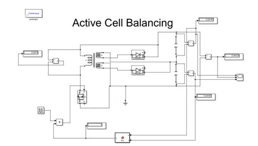
Fig.10 Active Cell Balancing Circuit
1. Construction:
This circuit can be completed with N number of capacitors depending on the no of cells and the voltage. This circuit is connected in a Flyback converter model to achieve its purpose. This circuit consists of a transformer with its secondary coil is connected to a diode which is then connected to the capacitor. The primary coil of the transformer connected to the other side of the capacitor. A MOSFET is connected to the circuit with the primary coil connected to it. The Source is also connected to MOSFET with the wire grounded. The produce is connected with a pulse generator to the third side of the MOSFET to control the circuit. Finally, a programed MATLAB function connected to the circuit with the output connected in the function and output connected to the capacitor
2. MATLAB function code:
- The Matlab function works in such a way that y is the output and u,v are input cells.
- If u and v have same voltage the output becomes zero
- If they aren’t similar the circuit continues to run
function y= fcn (u,v)
if (u<=v && v>=u)
y=0;
else
y=1;
end
3. Working:
- The Circuit works when the switch is turned on and the energy is stored in the transformer
- This energy cannot be transferred to the secondary coil because of the diode being reverse biased
- When the switch is turned off the energy can be transferred to the secondary coil which powers the whole circuit
- The capacitors will also help to store energy and equally distribute the charge throughout the cells.
4. Result:
From this circuit, optimum output has been achieved with the cells being perfectly balanced. By simulating it with different seconds, this is done by trial and error technique. This process has been repeated until the desired result where all the cells are balanced has been achieved.
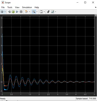
Fig.11 Resultant Active cell Balancing graph
From the graph, we can notice that the voltages present in the cells are different where one being high and one is being low initially. After the circuit is turned on the voltages are then regulated evenly and at the end, the voltage and state of charge level in both the cells were evenly balanced and the result was achieved.
7. Conclusion:
In the next few years, electric traction motor drives in automotive applications will see a huge rise in their market share. Using large battery or ultra-capacitor stacks as energy storage buffers is an essential part of the fuel-saving concept. The state of the art technology for the near future is lithium-ion batteries. With a low weight and an extremely high number of charge and discharge cycles, they offer high energy density.
However only if they are correctly managed their potentially high cycle life, calendar life, power capability, and safe operation, can be reached. Active charge balancing is essential, in addition to the exact monitoring of the voltage, current, and multiple temperature measurement points of each individual cell. The active method described in this paper has certain advantages compared to a passive balancing procedure such as the lower power dissipation for dramatically reduced cooling effort and lower temperatures in the system, better battery capacity usage based on balancing, higher overall vehicle fuel efficiency
Cell balancing methods, such as the one presented in our paper, will be a major factor in improving the performance of the battery and protecting the battery from damages induced due to overcharging and overvoltage at an industrial level.
8. References:
[1] Engineering.com. 2020. Battery Management Systems–Part 3: Battery Charging Methods. [online] Available at: <https://www.engineering.com/ElectronicsDesign/ElectronicsDesignArticles/ArticleID/19955/Battery-Management-SystemsPart-3-Battery-Charging-Methods.aspx> [Accessed 11 December 2020].
[2] Lecture 7, “Control of Electric Vehicles” Meng Auto, by Ryan Ahmed
[3] Rajkumar, A., 2020. Balancing Of The Weakest Cell In A 20-Cell Battery Pack Using Simulink Model.. [online] Skill-Lync. Available at: <https://skill-lync.com/projects/week-8-multi-cell-battery-pack-22?utm_source=Skill-Lync-Projects&utm_medium=linkedin-post&utm_content=week-8-multi-cell-battery-pack-22&utm_set=Akshat-Mathur-530> [Accessed December 2020].
[4] Piao, C., Wang, Z., Cao, J., Zhang, W. and Lu, S., 2015. Lithium-Ion Battery Cell-Balancing Algorithm for Battery Management System Based on Real-Time Outlier Detection. Mathematical Problems in Engineering, 2015, pp.1-12.
[5] Yusof, M., Toha, S., Kamisan, N., Hashim, N. and Abdullah, M., 2017. Battery Cell Balancing Optimisation for Battery Management System. IOP Conference Series: Materials Science and Engineering, 184, p.012021.
[6] Chen, B. and Lai, Y., 2012. New Digital-Controlled Technique for Battery Charger With Constant Current and Voltage Control Without Current Feedback. IEEE Transactions on Industrial Electronics, 59(3), pp.1545-1553.