Week 6-Meshing of Hood Challenge
Aim: The main scope of this project is to mesh the hood surface for Crash and Safety Test as per the Mesh Quality Criteria stated below:
|
S.N |
Quality Criteria |
Value |
|
1 |
Aspect Ratio |
5 |
|
2 |
Skewness |
45 |
|
3 |
Warping |
15 |
|
4 |
Taper |
0.5 |
|
5 |
Min. Length |
2 Units |
|
6 |
Max. Length |
8 Units |
|
7 |
Min angle Quad |
45 |
|
8 |
Max angle Quad |
135 |
|
9 |
Min angle Tria |
20 |
|
10 |
Max angle Tria |
120 |
|
10 |
Tria % |
10 |
Procedure:
In this Project, I have meshed the hood with MIXED option (QUADS and TRIAS) for crash and safety test. Whereas, for durability and structural simulation, we can use QUADS ONLY option.
Topology:
What are the topological repairs I could do before Meshing?
- As a responsible designer, we intend to design products with a lot of feature and construction lines. Construction lines do not define a feature of a model. Thus in the process of meshing, it is unnecessary to have too many construction lines as our mesh flow is affected while retaining the most significant construction lines to best capture the mesh.
- Nodes, they define the way the elements are meshed. A node could change the location of an element. It is necessary to get rid of temporary/unnecessary nodes.
- Feature lines, as it defines any feature of a surface such as a fillet, could only be compromised if the mesh size is not met. In my project, the minimum element size is 2. Thus I had gotten rid of fillet lines that were distanced less than 2. For this purpose, I had created a midline between two fillet lines before getting rid of them and trimmed the surface with that midline to bring out a proper mesh. This happens mostly in the hemming region that has a small cross section.
- Creating construction lines wherever necessary: while it is also important for us to get rid of too many construction lines, it is also important to create construction lines where we need it. It is always a good option to have square regions or rectangle regions for mesh when constructing the lines.
- Check for Equivalence: There is a possibility of missing surfaces in the model. We need to ensure that the model doesn’t have any missing surfaces.
The Designed Hood model is imported and the mid-surface of each part of the model is extracted by
Geometry-->Midsurface--> Select the solids or surfaces of the solid--> Extract.
The Hood model has 4 parts namely, the outer panel, the inner panel, latch and Hinge.
Thus we have mid-surface of the outer panel, the inner panel, latch and hinge models. The reason for converting a 3d model into a 2d surface is to save time in mesh.
When meshing the hood for crash and safety test purposes, there are a few thumb rules I have to follow.
- Achieve Proper Mesh Flow: Try to divide the object in equal portions so as to get proper amount of trias and quads by avoiding rotating quad elements. Apparently, if the number of nodes on one side is equal to the nodes on the other side (Like a square box), you will most likely have QUADS. It is mostly unlikely to have QUADS in converging regions, as it requires Trias in the converging direction to make the mesh less dense.
- Avoid Trias in these locations of a Model: There should not be trias near the holes, features, edge of geometry and fillet regions as it adds to additional stress in the component and thus it could affect the result due to stress.
- Try to get rid of tria concentrated regions:
It is necessary to avoid back to back triangles, opposite trias and heavily concentrated regions above 10% as the trias have a larger stiffness value than the Quads. So in this project, I have tried to get rid of as many triangles as possible to keep it below 10%.
A. Meshing - Outer Panel
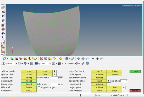
Fig.1 Suppressing unwanted construction lines
i. The Extracted mid surface of the outer panel is inspected and the unwanted construction lines that don’t define a good shape (to avoid sharp corners or edges) are toggled/supressed.
Geometry --> Quick Edit -->Toggle
Unwanted nodes are also removed using
Geometry --> Quick Edit --> Add/remove point
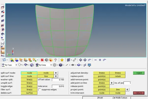
Fig. 2 Creating construction lines
ii. Creating new construction lines: Here I have supressed the irregular construction lines and created new construction lines that would divide the surface in equal squares. This will help me achieve better mesh results.
Geometry--> Quick Edit--> Split surf-node
Divide and Conquer:
It is neccesary to mesh the objects by individually meshing region by region, as the whole object if meshed, could raise more quality issues such as higher tria concentration, trias in the corner, trias in the feature region, opposite trias and also back to back trias. Thus I have meshed it square by square in my project.
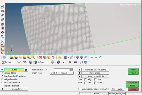
Fig.3 Meshing the hood by region
iii. I have set the mesh size and used mesh type as Mixed (That has both Trias and Quads). And I selected the square surface alone for meshing.
iv. Inspecting the meshed surface: As I observed irregular trias and quads, I made proper measures as per the thumb rule to bring a proper mesh flow. In the mesh flow shown below, the region isn’t converging but still I observed Trias pointing towards the edge.
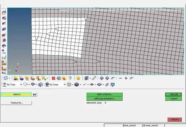
Fig.4 Rebuilding Mesh
v. To bring a proper mesh , we can rebuild the mesh in this region by
2D--> Rebuild mesh--> Select the elements--> Rebuild
The result after rebuilding is shown below:
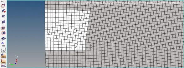
Fig.5 Solving Opposite Trias
vi. As shown above, there are two opposite trias that could be resolved into a QUAD. For dragging the trias together, we can use the option
2d--> Quality Index--> Clean-up tools --> Drag Tria
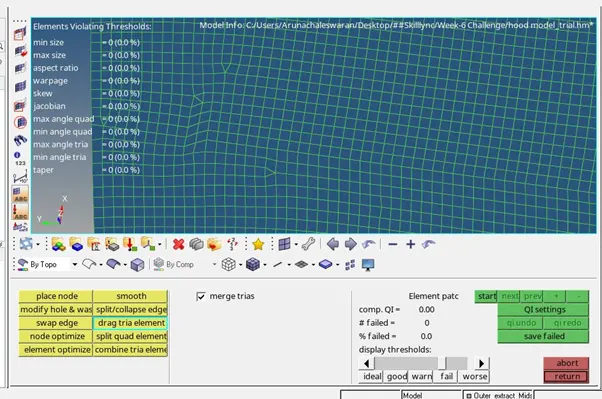
Fig.6 Dragging Tria Element
Using the drag tria element, I have dragged one of the tria closer to the other using my left click of the mouse.
And using the combine tria element option, the common edge of the trias elements can be collapsed to form a QUAD. (2d--> Quality Index--> Clean-up tools --> Combine Tria Element)
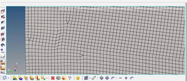
Fig. 7 After forming QUAD element
The resultant mesh is as shown below. But the mesh quality is still not retained to a good range hence we need to optimize the elements to get the desired shape of a QUAD or TRIA element.
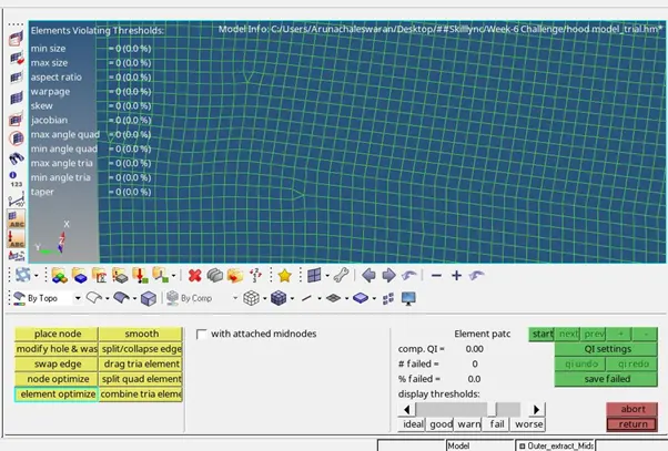
Fig.8 Element Optimize
2d--> Quality Index--> Clean-up tools --> Element Optimize would help in optimising the element to its corresponding shape.
The same procedure is repeated for other opposite Trias in other regions.
- Drag tria
- Combine Tria
- Optimize element
- Smooth element (Optional, useful for a curved surface) 2d--> Quality Index--> Clean-up tools --> Smooth
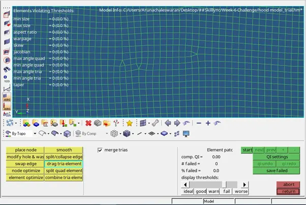
Fig.9 Dragging Tria
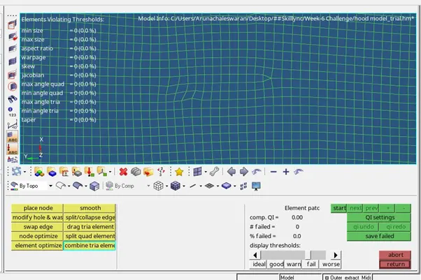
Fig. 10 Combining Tria elements into a Quad
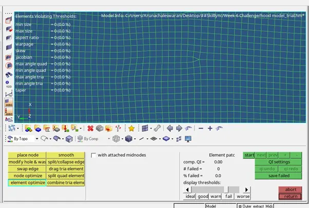
Fig. 11 Element Optimize
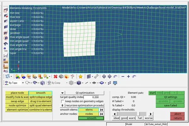
Fig.12 Smoothening Elements
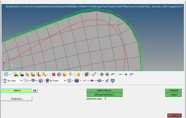
Fig. 13 Getting rid of Tria in corner
Vii: Getting rid of triangles in the edges of the geometry is important to avoid stress induced by the trias in the edge. To do that.
2D--> Rebuild mesh-->Select the elements--> Rebuild
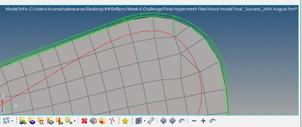
Fig. 14 Rebuilt Mesh
We can the resultant mesh after the rebuild option is clicked.
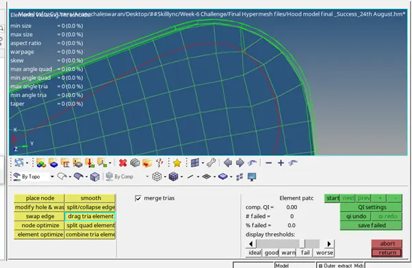
Fig. 15 Dragging Tria Element
2d--> Quality Index--> Clean-up tools--> Drag Tria element
In order to swap the elements needed. In this case, the tria was fixed and could not be moved. Hence we follow the steps to split and combine it into a quad.
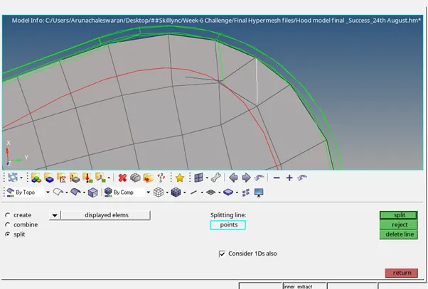
Fig. 16 Splitting Elements
2d--> edit element--> split radio button option
We can split by creating a line using this edit element option. By using the combine radio button we can merge the two elements using the combine option.
2dà Edit element --> Combine radio option--> click combine after selecting the elements.
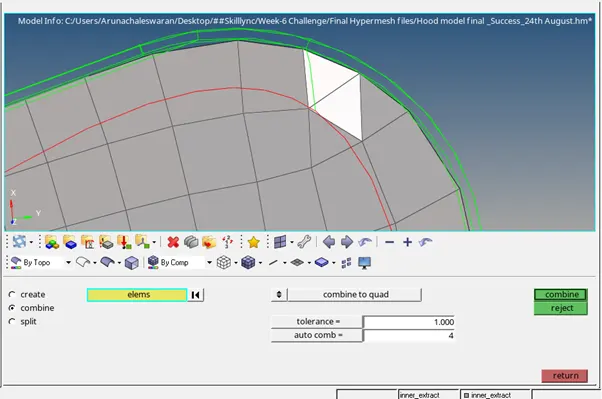
Fig. 17 Combining Elements
Now since I realized that we can replace the nodes of one triangle to eliminate the tria from the edge, we can use replace option from
2d--> replace--> select the nodes--> click replace --> click yes when a pop up appears
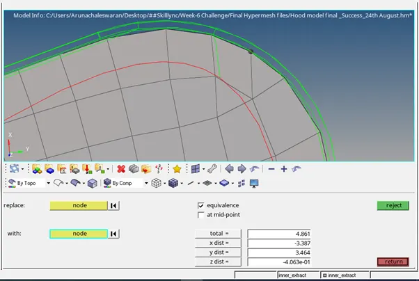
Fig. 18 Replacing Nodes to get rid of Tria
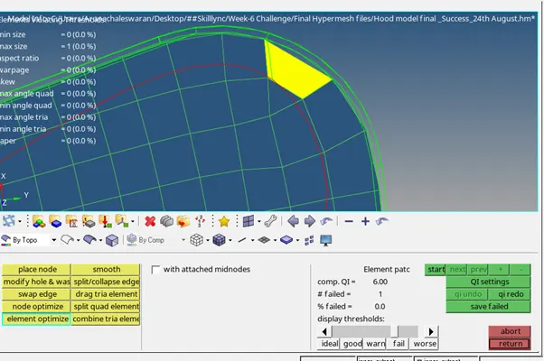
Fig. 19 Optimizing Elements
In order to optimize the element to eliminate the maximum size error, we can use
Element optimize option from Clean up tools again. Thus we can solve the issue with the element.
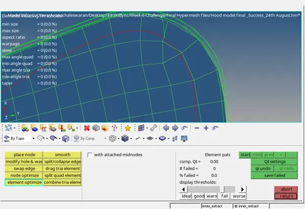
Fig. 20 Final mesh after eliminating tria in the edge.
Hence we get the resultant mesh without rotating quads and without any trias in the edges.
B. Meshing Inner panel:
Just like the outer panel, the mid surface of the inner panel solid is extracted.
Inner mesh panel was the tedious process to clean up as there were too many construction lines.
For the step 1, I performed geometry clean up on the surface.
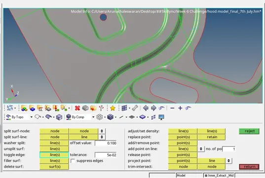
Fig. 21 Suppressing unwanted construction lines
- Geometry--> Quick Edit--> Toggle edge will enable you to remove the unwanted construction lines. Using this option, I had suppressed the lines that I did not need for the mesh operation. This reduces the possibility of meshing within these lines as the boundaries.
Blue lines indicate that the lines have been suppressed. Whereas the Green line indicates that the surfaces share the same line. But red line indicates that the surface has a free edge.
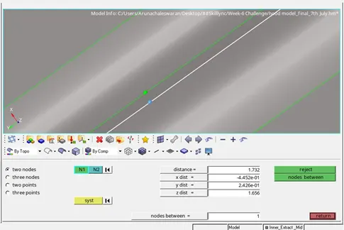
Fig. 22 Distance between fillets
2. We should not bother to suppress the fillet lines however if the distance between the lines are lesser the minimum element size (2), then the lines can be compromised. Before that we need to make sure that the surface has been trimmed with the mid-line extracted from these fillet lines.
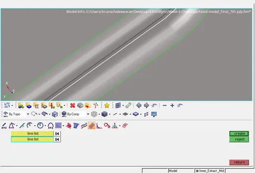
Fig. 23 Creating Midline
Geometry--> Lines--> Midline-->Select the two fillet lines and select create. This will create a new midline with which we can trim the surface to make sure the mesh will be captured nicely with this new mid line regardless of these two fillet lines.
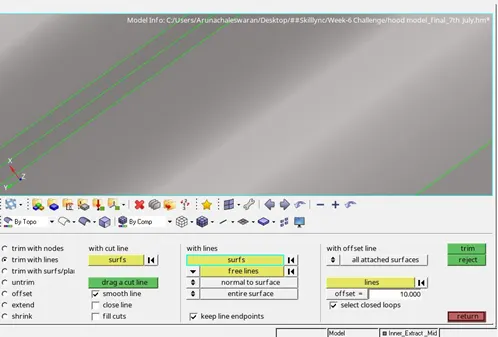
Fig. 24 Trimming Surface with Midline
Geometry--> Surface edit--> trim with lines -->with lines option.
Select the surface you want to trim and select the mid line you had created and hit trim button in the right corner. Make sure the “Normal to surface “and “entire surface” are checked.
As indicated in the red arrow, the surface is trimmed with the mid line. Now the fillet lines can be suppressed using the Toggle option.
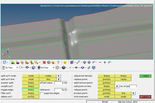
Fig. 25 Toggling unwanted construction lines in fillet regions
3. In this complicated fillet region, I had gotten rid of unwanted construction lines by using the toggle option. To best capture the fillet regions, we might also need to create a few construction lines.
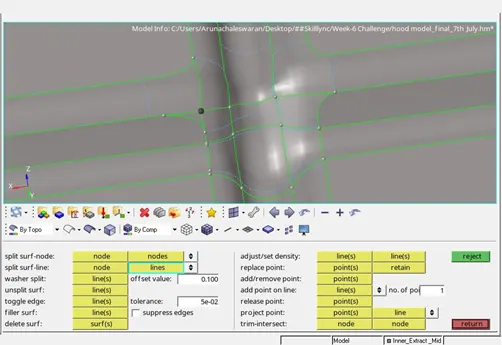
Fig. 26 Creating construction lines for better quality mesh
Using Geometry--> Quick edit -->Split surf-line. (to connect nodes with lines). I was able to achieve a construction line. Similarly I did with other fillet lines as well.
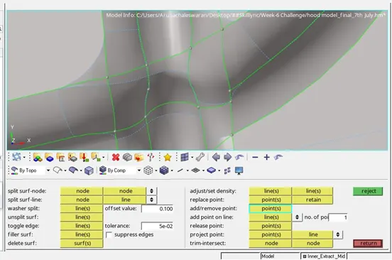
Fig. 27 Removing unwanted points
4. Using add/remove points, we can remove points by right clicking the unwanted nodes/points. It is available in the quick edit tool bar.
5. In the instances where rebuild mesh isn’t enough to get rid of the back to back trias, we can use 2D--> Edit element--> Split to move the tria forward.
To move any tria, this method could be used. It involves 3 easy steps.
- Drawing a split line to merge the tria with a quad as shown in the picture and creating a tria ahead.
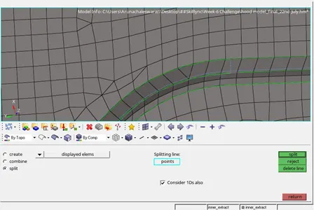
Fig. 28 Splitting the elements to move the tria forward
2. Combine the elements by using the combine option in the same edit element option.
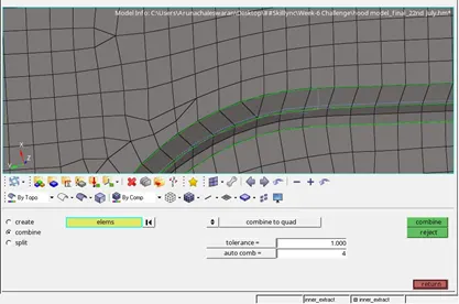
Fig. 29 Combining Elements
3. Smooth the elements to retain the actual node positions of the elements.
Use shift + F12 for shortcut or go to 2D-->Smooth option
Select the elements to smooth.
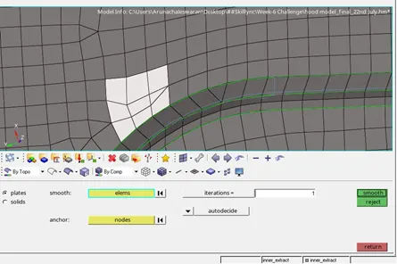
Fig. 30 Smoothing the elements to retain the original shape
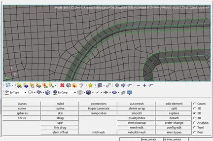
Fig. 31 Clearing the Back to back tria region
Thus I was able to avoid the back to back trias in this region by using this method.
6. Warpage issues- In most of the fillet regions warpage issues arise due to improper mesh sizes and elevation. This can be resolved using TRANSLATE option.
Tool-->Translate -->Select the nodes of the element that has warpage issue and translate the elements.
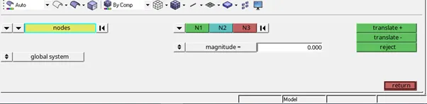
Fig. 32 Translate option
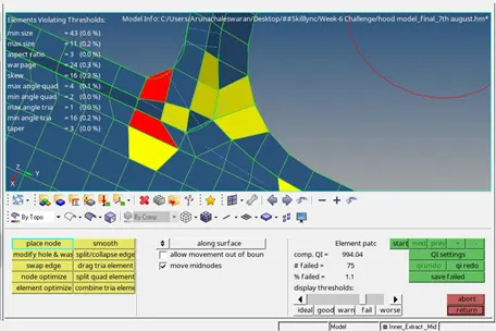
Fig. 33 Editing the elements to resolve the quality criteria error
7. Most of the mesh errors can be resolved by
- Clean up tools in the quality index of 2D panel
- Edit element in 2D panel
- Element clean-up in 2D panel
- Rebuild Mesh in 2D panel
- Project option in Tool panel
- Translate option in tool panel
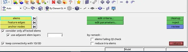
Fig. 34 Element Cleanup
2D-->Elem Cleanup-->Select the failed elements and the adjoining elements if needed. After clicking the cleanup, we will witness the correction made in the elements.
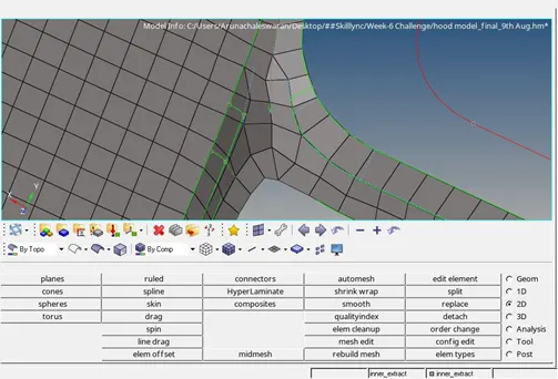
Fig. 35 Final Fillet region
C. Meshing Hinge and latch surface
- Just like the inner and outer extract, the mid surfaces of the hinge and latch solids are extracted. A geometry cleanup is done on the mid surfaces of these solids.
Geometry cleanup is done using the quick edit tool panel as shown in the pictures below:
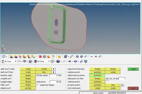
Fig. 36 Removing Unwanted points in hinge surface
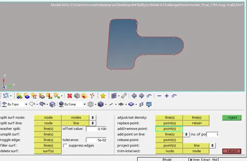
Fig. 37 Removing unwanted points in Latch surface
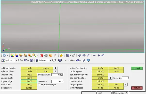
Fig. 38 Removing unwanted construction lines
After this geometry cleanup, the mesh operation is performed and the quality criteria is checked and corrected if there any errors in the mesh.
D. Elements Check
Method 1: Tool--> Check Elems will enable you to check if the elements have met with your requirements.
By keying in the quality criteria values, we can check the mesh for any element failure.
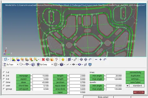
Fig. 39 Checking Elements
Method 2:
2D-->Quality Index
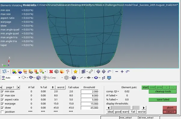
Fig. 40 Quality Index
Method 3:
This is a pre-preparation method that I followed. We can set all the parameters before meshing or rebuilding mesh. This is the easiest method, as the elements are laid as per your quality criteria. However one may need to do an element cleanup and check after meshing.
2D--> Rebuild Mesh--> Edit criteria
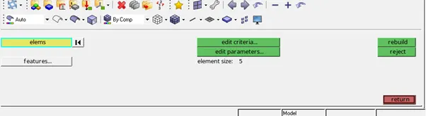
Fig. 41 Editing Mesh Criteria
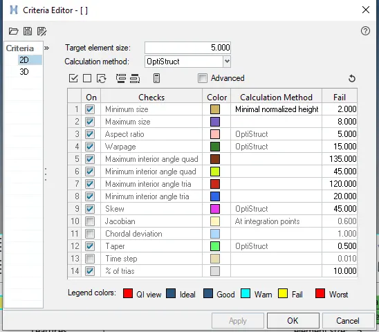
Fig. 42 Mesh Quality Criteria Editor
We can set our quality parameters in this criteria window that appears. Once we click apply, our mesh is built/rebuilt using this quality criteria. In this criteria I set the values as below
|
S.N |
Quality Criteria |
Value |
|
1 |
Aspect Ratio |
5 |
|
2 |
Skewness |
45 |
|
3 |
Warping |
15 |
|
4 |
Taper |
0.5 |
|
5 |
Min. Length |
2 Units |
|
6 |
Max. Length |
8 Units |
|
7 |
Min angle Quad |
45 |
|
8 |
Max angle Quad |
135 |
|
9 |
Min angle Tria |
20 |
|
10 |
Max angle Tria |
120 |
|
10 |
Tria % |
10 |
Result:
Hence I was able to perform a good quality mesh on the hood of a car as per the quality criteria values successfully.
The result images of the mesh of
- Outer Panel
- Inner Panel
- Hinge
- Latch Surface
are shown below:
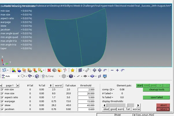
Fig. A Outer Panel Mid-Surface Mesh Quality Criteria Check
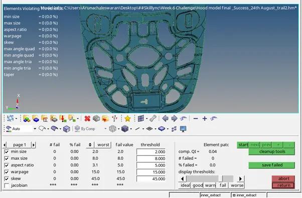
Fig. B Inner Panel Mid-Surface Quality criteria check
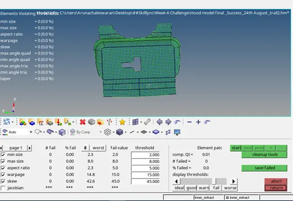
Fig. C.1 Latch Mid-surface Quality criteria check
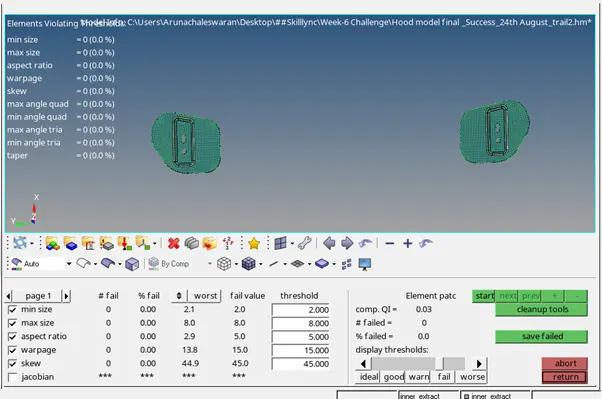
Fig. C.2 Hinge Surface Mid-surfaces Quality Criteria Check
Attachments: HM files, Report documents