Buckling analysis of a cyclonic separator stand
Aim: To perform buckling analysis on a cyclonic separator stand
Objective:
- To model a cyclonic separator stand and a metallic stiffener on the legs of the stand
- To perform buckling analysis on a cyclonic separator stand
- To find out the variation of factor of safety w.r.t offset distance from the base
- To find the optimum postion of the stiffener
Introduction:
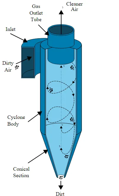
CYCLONE SEPARATOR CYCLONIC SEPARATOR WITH STAND
Cyclonic separator
- Cyclone separators or simply cyclones are separation devices (dry scrubbers) that use the principle of inertia to remove particulate matter from flue gases. Cyclone separators is one of many air pollution control devices known as pre-cleaners since they generally remove larger pieces of particulate matter. This prevents finer filtration methods from having to deal with large, more abrasive particles later on. In addition, several cyclone separators can operate in parallel, and this system is known as a multicyclone.
- It is important to note that cyclones can vary drastically in their size. The size of the cyclone depends largely on how much flue gas must be filtered; thus, larger operations tend to need larger cyclones. For example, several different models of one cyclone type can exist, and the sizes can range from a relatively small 1.2-1.5 meters tall (about 4-5 feet) to around 9 meters (30 feet)—which is about as tall as a three-story building.
Finite element analysis (F.E.A)
- Finite element analysis (FEA) is the process of simulating the behaviour of a part or assembly under given conditions so that it can be assessed using the finite element method (FEM). FEA is used by engineers to help simulate physical phenomena and thereby reduce the need for physical prototypes, while allowing for the optimisation of components as part of the design process of a project.
- FEA uses mathematical models to understand and quantify the effects of real-world conditions on a part or assembly. These simulations, which are conducted via specialised software, allow engineers to locate potential problems in a design, including areas of tension and weak spots.
- With the use of mathematics it is possible to understand and quantify structural or fluid behaviour, wave propagation, thermal transport and other phenomena.
- Most of the processes can be described using partial differential equations (PDEs), but these complex equations need to be solved in order for parameters such as stress and strain rates to be estimated. FEA allows for an approximate solution to these problems
Buckling analysis
In many design projects, engineers must calculate the factor of safety (FOS) to ensure the design will withstand the expected loadings. Calculations require correctly recognizing the mechanisms of failure, and this is a difficult task. All too often we associate structural failure only with yielding and are satisfied when design analysis shows a sufficient FOS related to yield.
Procedure:
Step 1: Creating a 3 D Model
A 3D model of cyclonic seperator is shown above. For buckling analysis only the frame is considered and all the other parts arew suppressed. The suppressed view is shownbelow. From simulation tab New study is selected and from that buckling is chosen.
Step 2: Material selection
Alloy steel was chosen as the material.
Step 3: Meshing
Meshing is done to divide the frame into small solid elements whose size is specified by the user. Optimum mesh size is selected by running the analysis until the solution converges. The meshed frame is shown below.
Step 4: Boundary conditions
The bottom faces of the four legs are given fixed constraint and a force of 150kN is applied in the downward direction on the top face as shown below
Step 5: Post Processing
The result is shown below. The Buckling factor of safety is 27.7492 which is greater than for the frame without stiffner hence the stiffness of the frame can be improved by adding a stiffner.
OPTIMUM POSITION ANALYSIS OF THE STIFFENER
From the design study new study was chosen. The variable selected was the distance of the leg as we have to adjust the position of the stiffness along the length of the leg the values range from .25m to 1.75m. Constraints were given to maximize the Buckling factor of safety with least value as 25. The goal was to maximize the buckling factor of safety.Different scenarios is shown in the results section
While running the design study the solver solves for different scenarios and the optimum one was found to be scenario 4. The stiffener should be kept at a distance of 1m and the Buckling FOS was obtained 27.8 which is the maximum of all the other scenarios.
Model:
Material Properties: Alloy steel
3D model of the stand with a metal stiffener
Mesh with a load on the top face and fixtures at the bottom legs
Analysis:
Pre-processing:-
- Analysis type:- buckling analysis
- Material of the beams used is Alloy Steel.
Solving:-
- Fix the legs of the stand and apply load on the top of the stand.
- Analysis is done for the stand of the cyclonic separator for different cases as without stiffener, with stiffener and by variation of the position of the stiffener to determine the best position of the stiffener for maximum factor of safety by run the parametric study.
Post Processing:-
- Results of the simulation are plotted and analysed.
- After plotting, the results compare all the results for best position of the stiffener for maximum factor of safety.
Buckling analysis
Design study factor
Results:
Observations:
- From the first case study cyclone separator stand without stiffener in that result we get the Buckling FOS is 9.3941, but if we use the stiffener definitely we will get the more Buckling FOS.
- In the design study Cyclone separator with stiffener we are getting the Buckling FOS is 27.749422 at an optimum offset distance from the top of the table is 1000mm.
Conclusions:
By following the above steps, we were able to succesfully perfom buckling analysis on a cyclonic separator stand.