Boeing-747 _ Final_Project
Design of Boeing-747-8 using Solidworks
A Project Report Submitted in the fulfillment of the requirement for
Online Solidworks course
By
Pattan Akram
Under the Supervision of
Mr.Bharath kumar
Aim:
Having hands-on experience in modelling a complex design like that of the Boeing 747-8 in solidworks.
Objective:
In this project the main objective is to design a Boeing-747-8 Air craft using Solidworks software. We have used all the features in the solid works software. By the end of the course each and every individual part is assembled which result in the 3D-model of the Boeing-747-8. In this project we have learnt from solid surface modeling to assembly experiencing all the features in the software which helped to gain a knowledge over designing a complex design.
Parts modeled and command used:
Fuselage:
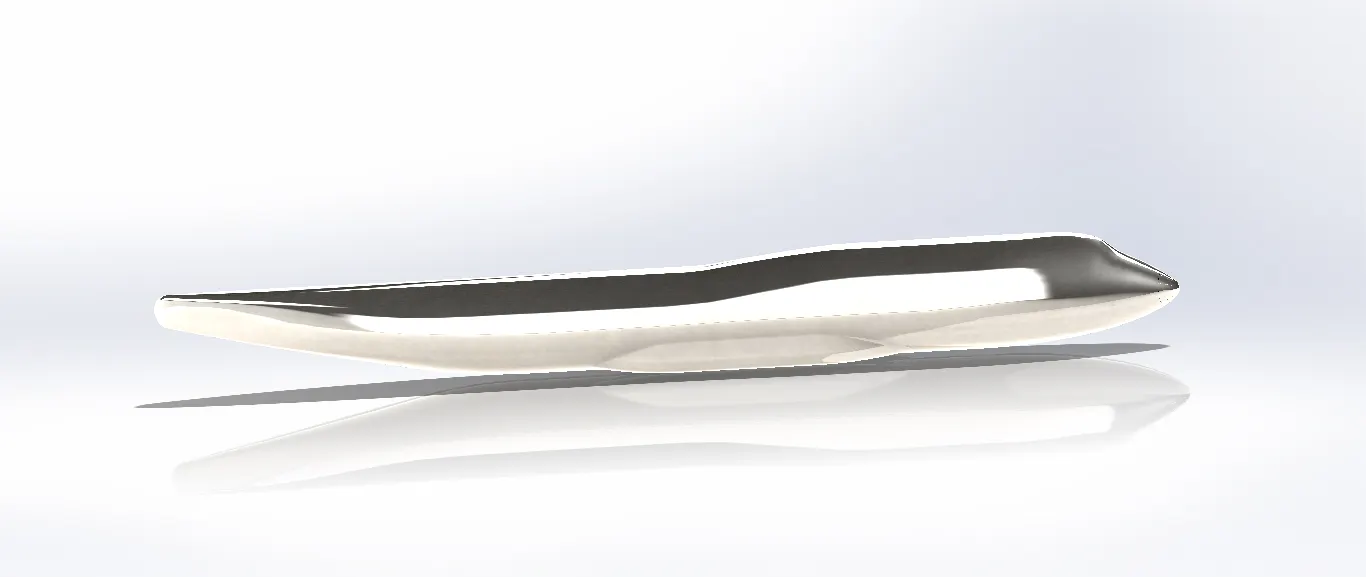
The fuselage, of the airplane, is a long hollow tube which holds all the pieces of an airplane together. The fuselage is hollow to reduce weight. As with most other parts of the airplane, the shape of the fuselage is normally determined by the mission of the aircraft. A supersonic fighter plane has a very slender, streamlines fuselage to reduce the drag associated with high speed flight. An airliner has a wider fuselage to carry the maximum number of passengers. On an airliner, the pilots sit in a cockpit at the front of the fuselage. Passengers and cargo are carried in the rear of the fuselage and the fuel is usually stored in the wings. For a fighter plane, the cockpit is normally on top of the fuselage, weapons are carried on the wings, and the engines and fuel are placed at the rear of the fuselage.
In order to design this fuselage initially we have designed a sketch using the blue prints of the Boeing 747-8, by using the projection curve the sketches on different planes is converted to a 3d sketch and by using the loft boss command the fuselage is created
Engine:
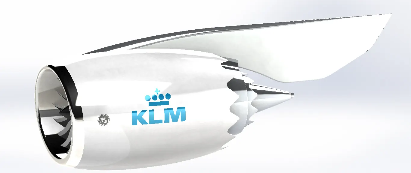
The aircraft has four engines mounted under the wings. The engine selected for the aircraft is the GEnx-2B67, the General Electric next-generation engine. The design of the 747-8 aircraft engine is slightly modified variant of the GEnx engine developed for the Boeing 787 Dreamliner aircraft. The engine provides 66,500lb of thrust.
The engine has composite front fan blades of diameter 105in, a high-pressure ratio compressor, and a twin-annular pre-swirler combustor to achieve lower emissions.
The combuster design provides efficient mixing of the fuel prior to ignition which yields lower nitrogen oxide levels and improved life.
The dual turbine configuration comprises a high-pressure first turbine and a second counter-rotating low-pressure turbine which provides improved fuel burn characteristics.
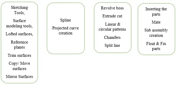
Explanation of the Flow chart:
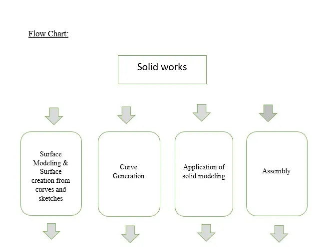
Surface Modeling & Surface creation from curves and sketches
- Sketching Tools: Tools like line, circle, rectangle, spline point all these are used to create a sketch on our desired surface or plane. It also has smart dimensions which is used to give dimension and make the sketch fully defined.
- Lofted Surfaces: It is a command used to loft a body using a sketch and a guide curve. We can loft any kind of shape depending on the sketch and the guide curve
- Reference Planes: It is a command used to create a new plane depending on the location of the sketch to be drawn.
Projected Curve Generation
- It is command used to produce a resultant curve of two other curves drawn in different planes and It is also 3d curve.
Application of solid modeling
- Revolve boss: It is a command used to create a body by using a sketch and an axis of rotation.
- Extrude cut: It is used to create a desired cut through a solid body.
- Linear & circular Pattern: It is used to create a like body or like features in a linear pattern or circular pattern.
Assembly
- Inserting parts: It is used to insert parts in order to do the assembly.
- Mate: It is used to give relationship between different parts that are to be assembled.
- Float & Fixed part: It is used to float and fix the part over the work space.
Different Parts & Assemblies Modelled:
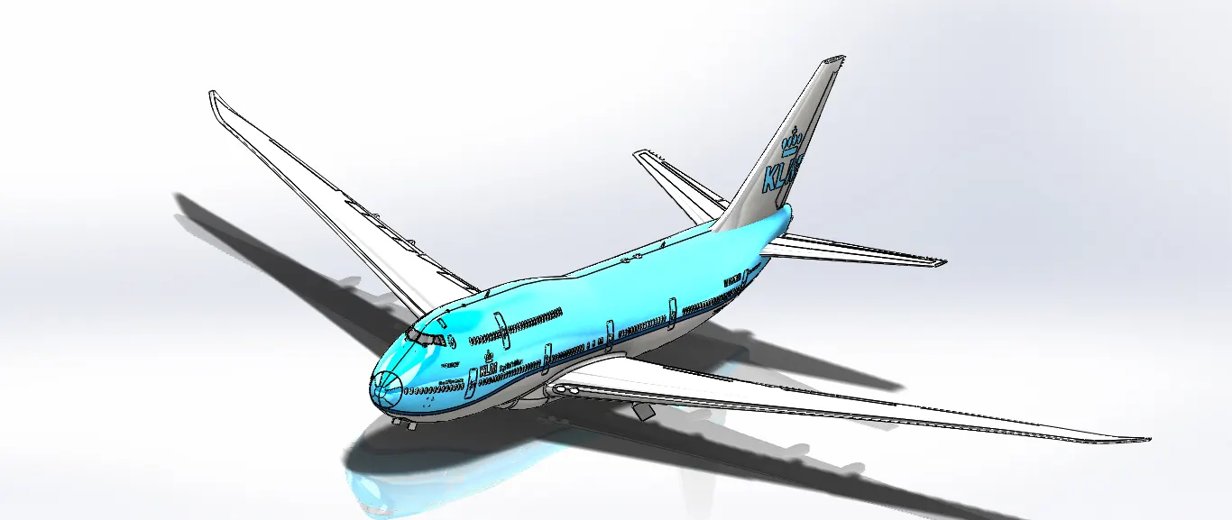
- The above part is modeled using the sketch tools and loft Boss, Split Line and appearance.
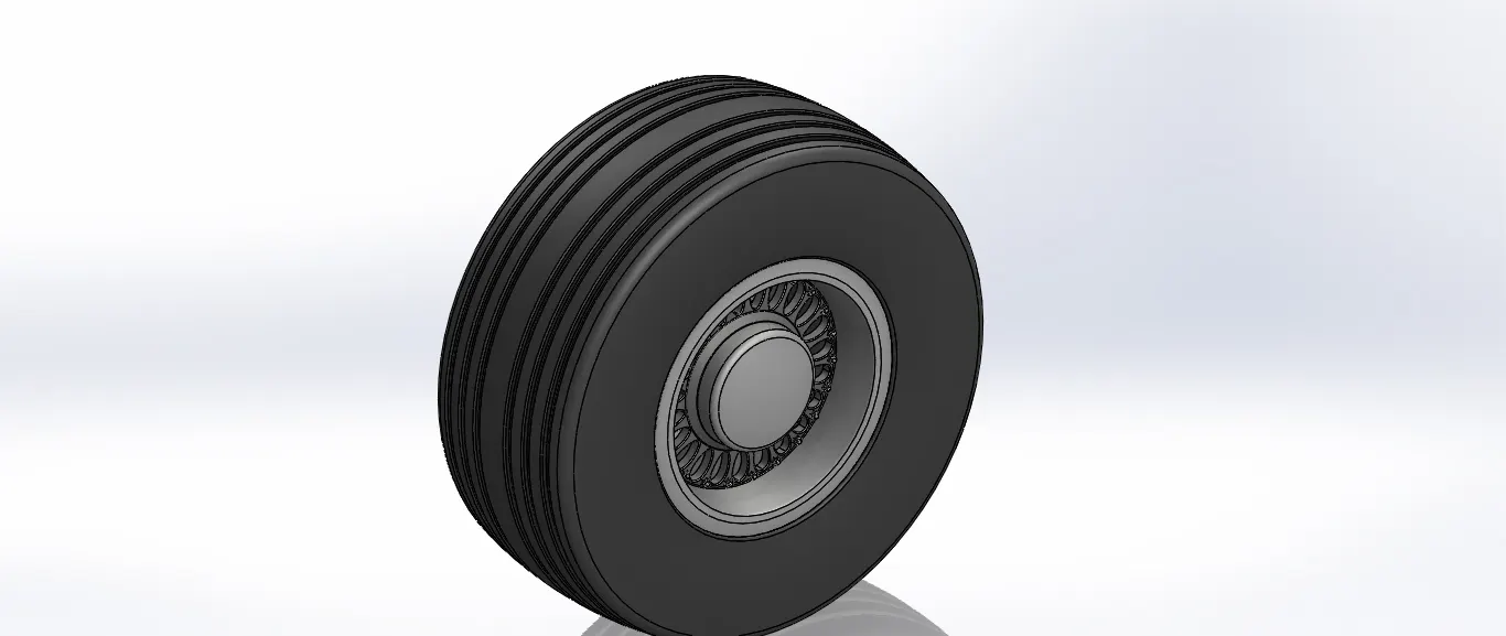
- The above part is created using revolved boss, revolve cut, shell, cut extrude, circular pattern
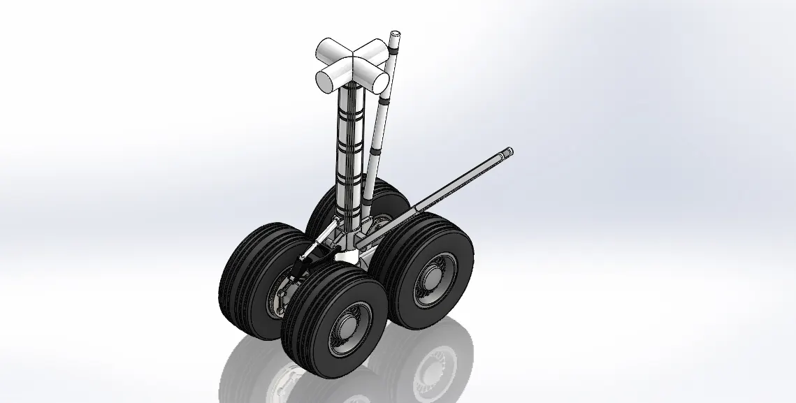
- The above model is obtained by creating the main gear base , main gear suspension and the wheels separately and all the parts are assembled using coincidence and concentric mate.
Final Assembly:
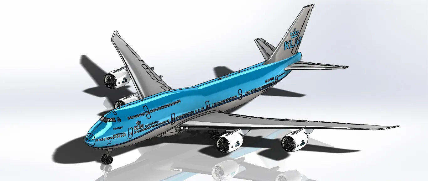
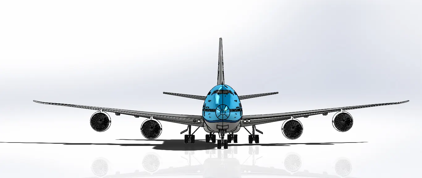
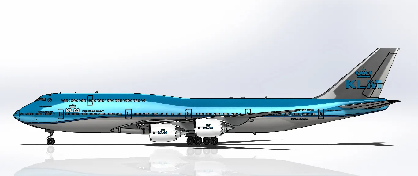
Conclusion:
By using the solid works software we have finally designed a 3d-model of Boeing 747-8.