Boeing-747 _ Final_Project
Solid Modelling, Assembly and Rendering of Boeing 747
Objective:
To model parts of Boeing 747 and assemble them in SolidWorks. After the assembly, Boeing 747 is then rendered for photo realistic view using SolidWorks Visualize.
Introduction:
SolidWorks is a 3D modelling software developed by Dassault systems. It enables the user to create/model parts, assemble them and sheet metal design etc., The designing of model is achieved by using various features in the software and most used features have been listed below:
Commonly used features in Part design:
- Part design has two types of features i.e., sketch tools and 3D features
- Sketch tools consists of 2D elements like line, Polygons (different types of rectangles), Circles, Arcs, Splines (a 2D line which can be controlled by control points), etc.,
- A 3D feature converts the sketch or 2D element into a 3-dimensional object by using features like Extrude, extrude cut, revolve base, Revolve cut, Sweep, Lofted base etc.,
- Surface is a two-dimensional object with zero thickness.
- Extrude: It is a 3D features which will be used in all most every part design. It adds thickness to a given sketch or 2d drawing. Depending upon the requirement of design, different types of extrudes are available.
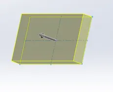
- Extrude Cut: It is similar to the extrude except it removes the material from the object. It also has different types depending upon the type of removal.
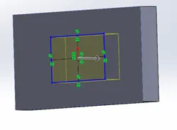
- Revolve: This feature is used to generate circular bodies around an axis. When a cross-section is revolved around an axis by adding material, then 3D object is produced.
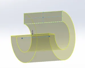
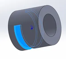
- Revolve Cut: It removes the material from an object in a revolved manner about an axis. The required cut of the material is achieved by revolving a cross-section around desired axis.
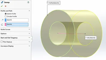
- Sweep: It is produces 3D objects of uniform cross-section from two sketches of which one acts as cross section, and another sketch acts a guide curve or center line which guide the given cross-section through out the span. The cross-section can be a rectangle, circle, square or any closed path while the guide curve may be a straight line, spline, or arc, etc.,
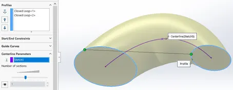
- Lofted Base: It produces 3d objects from the sketches which are on different planes. Objects with Variable cross-sections are produced using this feature. The path of cross-section of the object can be monitored by guide curves.
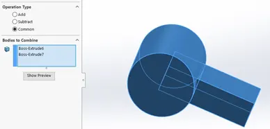
- Combine: By using this feature, Solids of different shapes or cross-sections can be combines to generate a new complex design.
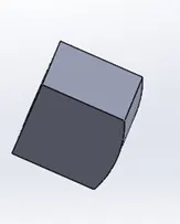
Result
- Split: When two bodies are merged into on another, by using spilt feature they can be separated or to avoid the surfaces of an object, split can be used to avoid the merging.
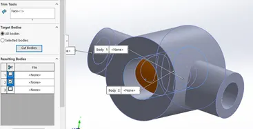
Highlighted part will be deleted
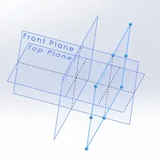
- Plane: This feature is used to generate new planes as it is not possible to create body on the given planes.
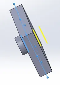
- Mirror Entities: This feature is used to mirror the bodies or features with reference to an axis or a plane.
- Patterns: This feature is used to copy an object for multiple times in a single operation. There are different types of Patterns like Linear pattern, Circular pattern and Spline or curve driven patter.
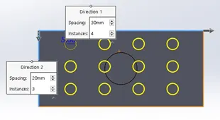
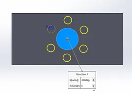
Linear Pattern in 2 directions Circular Pattern
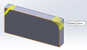
- Fillet: this feature eliminates the sharp edges by adding a rounded edge. It can be either constant radius fillet or variable radius fillet.
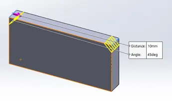
- Chamfer: This feature also eliminates the sharp edges but by adding a sloped edge. It can be added by giving the distance from edge onto two face or depth of chamfer with an angle.
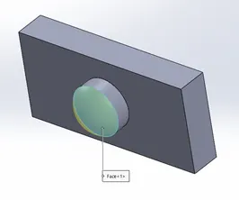
- Dome: This feature provides concave or convex surface on flat surfaces.
- Shell: This feature produces the hollow parts for solid bodies with defined thickness.
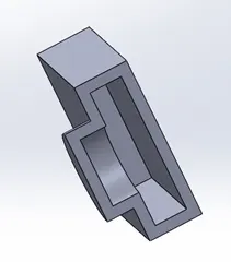
- Offset Surface: Creates a surface parallel to an existed surface at a defined distance.
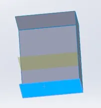
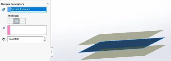
- Thicken: Adds thickness to the surface.
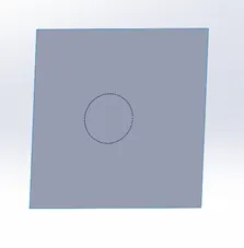
- Split Line: This feature divides the surface into multiple surfaces with a defined sketch.
- Projection Curve: It is a 3D Curve produced by combining two sketches from different planes or projection of a sketch on a selected surface.
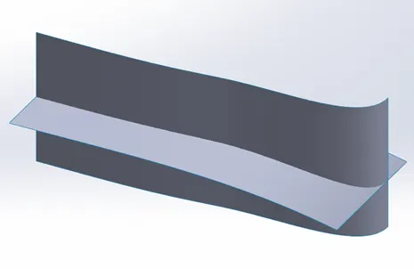
The intersection of two surfaces is a projection curve. It can not be achieved by a single sketch itself.
Design Approach:
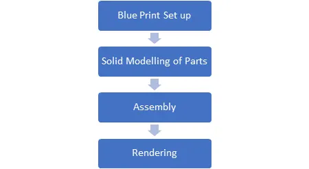
Parts Designed for Boeing 747:
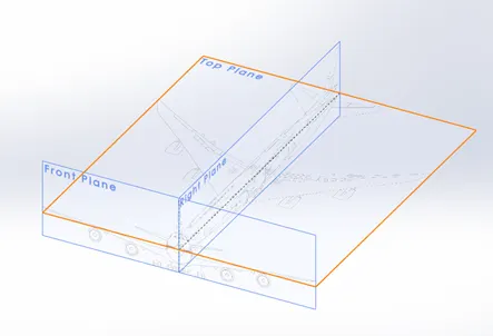
Blueprint Setup:
These are sketch pictures of desired model from different views like front, side and top views. With proper postioning and dimensioning of these blueprint, the job of part modelling will be easier.
Fuselage:
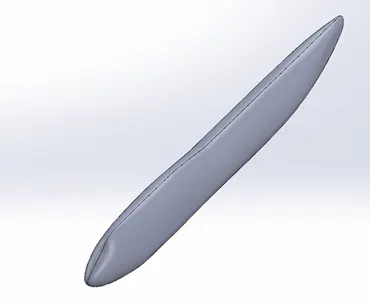
Fuselage is the mainbody of an aircraft which facilitates the space for passengers, driver cabin(cockpit).
Features used:
- Surface Loft
- Mirror
- Solid Conversion
Half of the surface of fuselage is designed and then it is mirrored and combined into a single body. Then the surface body is converted into a solid body.
Belly Fairing:
It is placed below the fuselage to provide extra space for cargo or fuel.
Features used:
- Extrude Base
- Mirror
- Fillet
- Combine
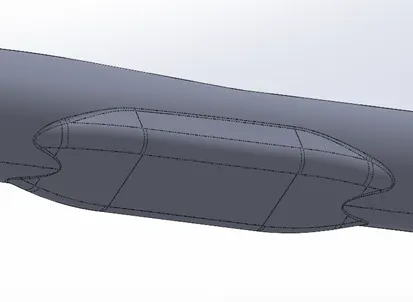
Nose Cone:
It is the front of the fuselage which reduces the drag on body of aircraft.
Features used:
- Split Line
- Sweep
- Mirror
- Fillet
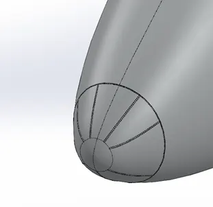
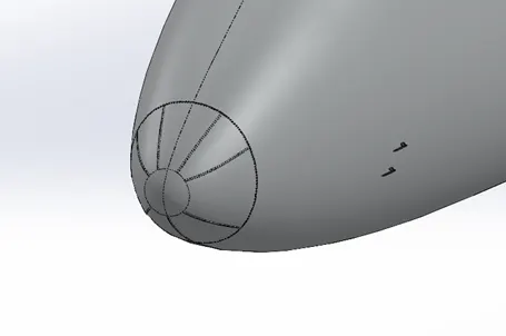
Pitot Tubes:
These are used to determine the spped of aircraft. An aircraft contains 2 pitot tubes on the right side and 2 on the other side.
Featues used:
- Extrude Base
- Sweep Base
- Chamfer
- Refernce Planes
- Mirror
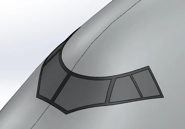
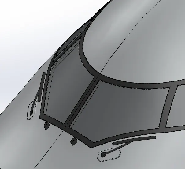
Cockpit Windows:
Simply known as winshield of pilot cabin. It provides visibility to the pilot in the cockpit.
Features used:
- Split Line
- Surface Offset/Surface Copy
- Thicken
- Fillet
Windshield Wipers:
These are used to clean the windshiled windows.
features used:
- Extrude Base
- Sweep Base
- Fillet
- Mirror
- Combine
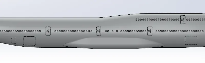
Passenger Doors, Windows and Hatches:
Doors facilitates the entry of passengers into plane or their exit. Windows provides the visibilty of outer areas to the passenger while travelling through the plane. This model contains a total of 250 windows on both right and left side. There are 6 doors on the right side of plane and 6 doors on the left side as well. There is 3 hatches on the right side of plane and an extra hatch is provided on the top right side of cockpit window.
Features used:
- Split Line
- Linear Pattern
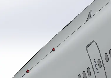
Lights and Antennas:
Lights are used to indicate its presence to other planes. Antennas are used to receive or emit the signals from plane. There are 2 lights on the top side of plane and 3 antennas are provided on the top and one is provided at the bottom side of plane.
Features used:
- Revolve Base
- Split
- Boss Extrude
- Fillet
- Draft
- Copy
- Linear Pattern
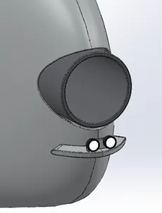
Auxiliary Power Unit:
It provides energy for applications like air conditioning, Electricity while the engine provides energy for propulsion.
Features used:
- Extrude cut
- Extrude Base
- Split Line
- Surface offset
- Thcicken
- Fillet
- Dome
- Mirror
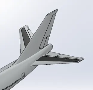
Stabilizers:
These are used to provide stability for aircraft. A vertical stabilzer is placed ate the rear top of fuselage and two vertival stabilizers are provided at the rear of plane on both sides,
Features used:
- Lofted Base
- Extrude Cut
- Mirror
- Surface offset
- Thcken
- Fillet
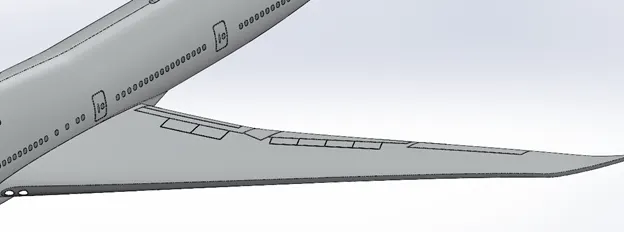
Wings:
It is used to produce the lift required for aircraft takeoff. There are 2 wings placed on each side of plane.
Features used:
- Projected Curve
- Lofted Base
- Reference Planes
- Variable Fillet
Flaps and Ailerons:
These are used to reduce the stalling speed of an aircraft. These are provided on the back of wings.
Features used:
- Extrude Cut
- Split Line
- Surface offset
- Thicken
- Fillet
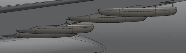
Flap Track Fairings:
These additional components of wings to reduce stalling Speed and placed at the bottom of wings. Each wing has 4 flap track fairings.
Features used:
- Extrude Base
- Split
- Variable Fillet
- Constant Radius Fillet
- Copy
- Mirror
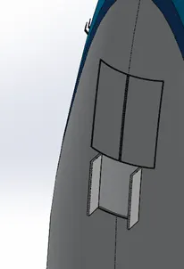
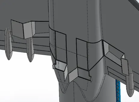
Landing Gear Hatches closed and open:
These are the casings of nose gear and main gear gear of air crafts. The front hatch provides space for the nose gear assembly and the hatches at the belly fairing provides space for main and body body gear assemblies. These will be opened when the plane is lading and will be close once the plane is taken off.
Features used:
- Split Line
- Surface Offset
- Thicken
- Fillet
- Extrude cut
- Refernece planes
- Sweep surface
- Ectrude Base
- Fillet
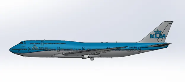
Livery:
Features used:
- Split Line
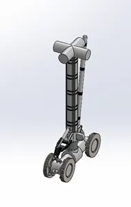
Main Gear Base:
This is the main component of the main landing gear assembly. The assembly is placed at the bottom of the belly fairing and activated when the plans is on the land. It will be closed by landing gear hatches at the belly fairing when plane is flyingg.
Features used:
- Extrude Base
- Extrude cut
- Linear Pattern
- Curicular Pattern
- Fillet
- Sweep Base
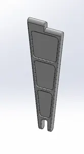
Main Gear Suspension Arm:
This is used to restrict the reciprocation motion of main gear base when being activated and deactivated.
Features used:
- extrude Base
- Extrude Cut
- Mirror
- Fillet
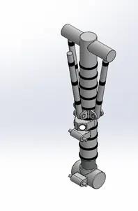
Nose Gear Base:
Landing gear assembly at the nose is called Nose gear assembly and serves the same purpose as the main gear base.
Features used:
- Extrude BAse
- Extrude Cut
- Linear Pattern
- Circular Pattern
- Mirror
- Combine
- Fillet
Nose Gear Suspension Arm:
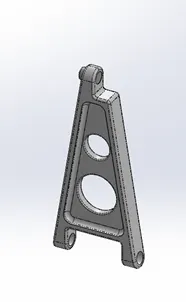
It restricts the motion of nose gear base and keeps it firmly when the plane is moving on runway.
Features used:
- Extrude Base
- Extrude Cut
- Fillet
Wheel:
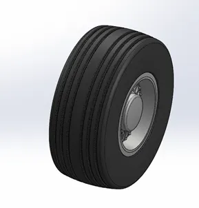
Wheel Provides the motion of aircraft when it is moving on runway. It Consits of tire, rim and bolt heads.
Features used:
- Revolve base
- Revolve Cut
- Extrude Base
- Extrude Cut
- Circular pattern
- Mirror
Engine:
It generates energy required for propulsion of aircraft. Boeing 747 uses GEnX - 2B67 engine developed by General Electric.
Features used:
- Revolve Base
- Split
- Shell
- Extrude Cut
- Fillet
- Circular Pattern
- Loft Surface
- Thicken
- Chamfer
- Variable Fillet
- Combine
Assembly:
The relation between the parts is defined by mates. There are different types of mates in the assembly:
- Concentric Mate
- Coincident Mate
- Parallel Mate
- Width Mate
- Gear Mate
- Angle Mate
The asembly is divided into 3 subassemblies.
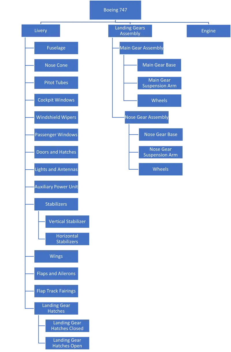
There are 4 main gear assemblies in the boeing 747 at belly fairing and each wing.
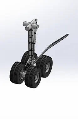
Main Gear Assembly
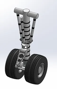
Nose Gear Assembly
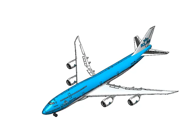
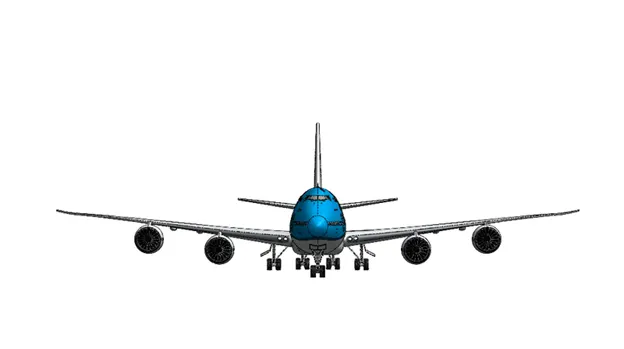
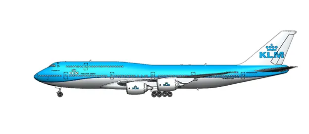
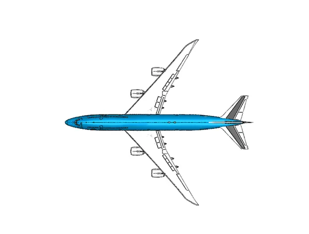
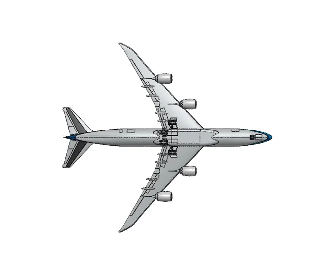
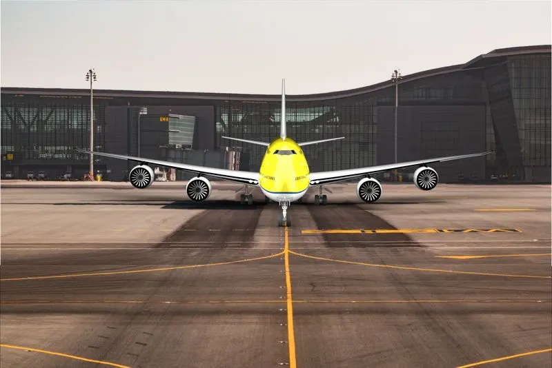
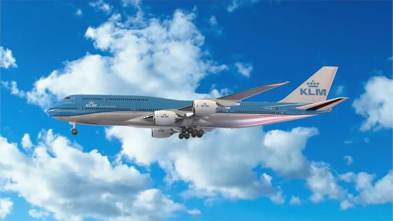
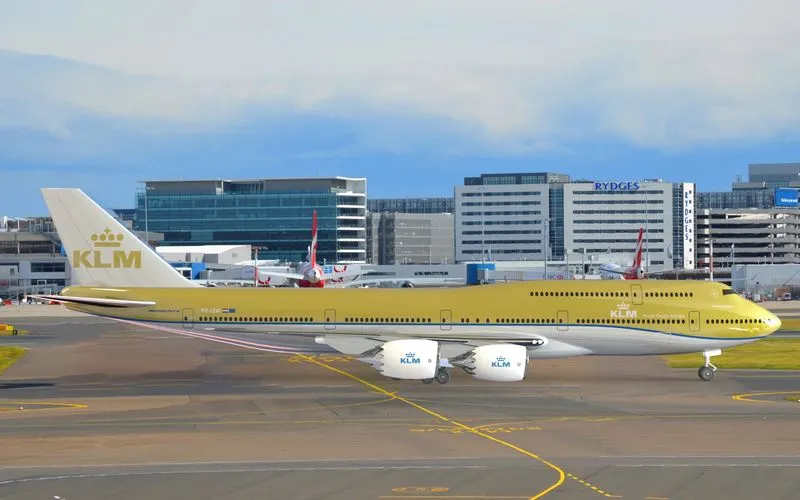
Solidworks Visualize: This software will help the designer to create realistic images of designed parts by using different environments. The environment or scene can be a pre-loaded scene in the software or a user defined image. There are variety of options like camera which enables the view of part from different angles, adjustable environment settings and appearance of the object.
RENDERING:
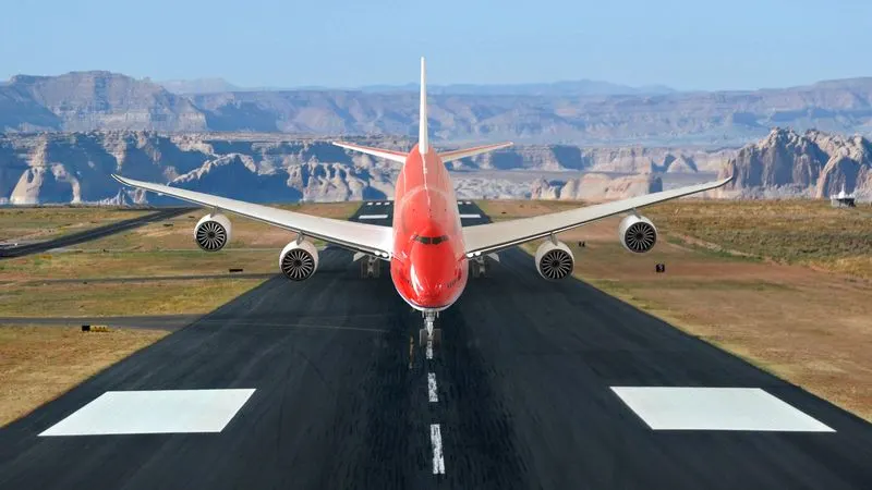
Rendering is done to apply real time graphics to the model. We can assign a scene or environment in which the Plane is placed, and we can modify the colors or looks of it. We can use different situations like sunny, or dark environments to check the behavior or looks of the designed model under a particular condition. We can apply different view positions to view it from different positions and angles to come to a conclusion about its design.
Conclusion:
With the complicated parts of Boeing 747, Several features of solid modelling and different apporaches for the design of parts are explored.