Simulating Backward facing step in Openfoam
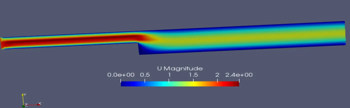
Aim : To simulate the backward facing step and to analyze the solution obtained by using different mesh grading factors.
Thoery :
The flow through a backward step is solved and analyzed using open foam and inorder to create the geometry 5 blocks are assumed to complete the geometry. This is done so as to capture the formation of boundary layer and velocity profile at step.
Rough Geometry :
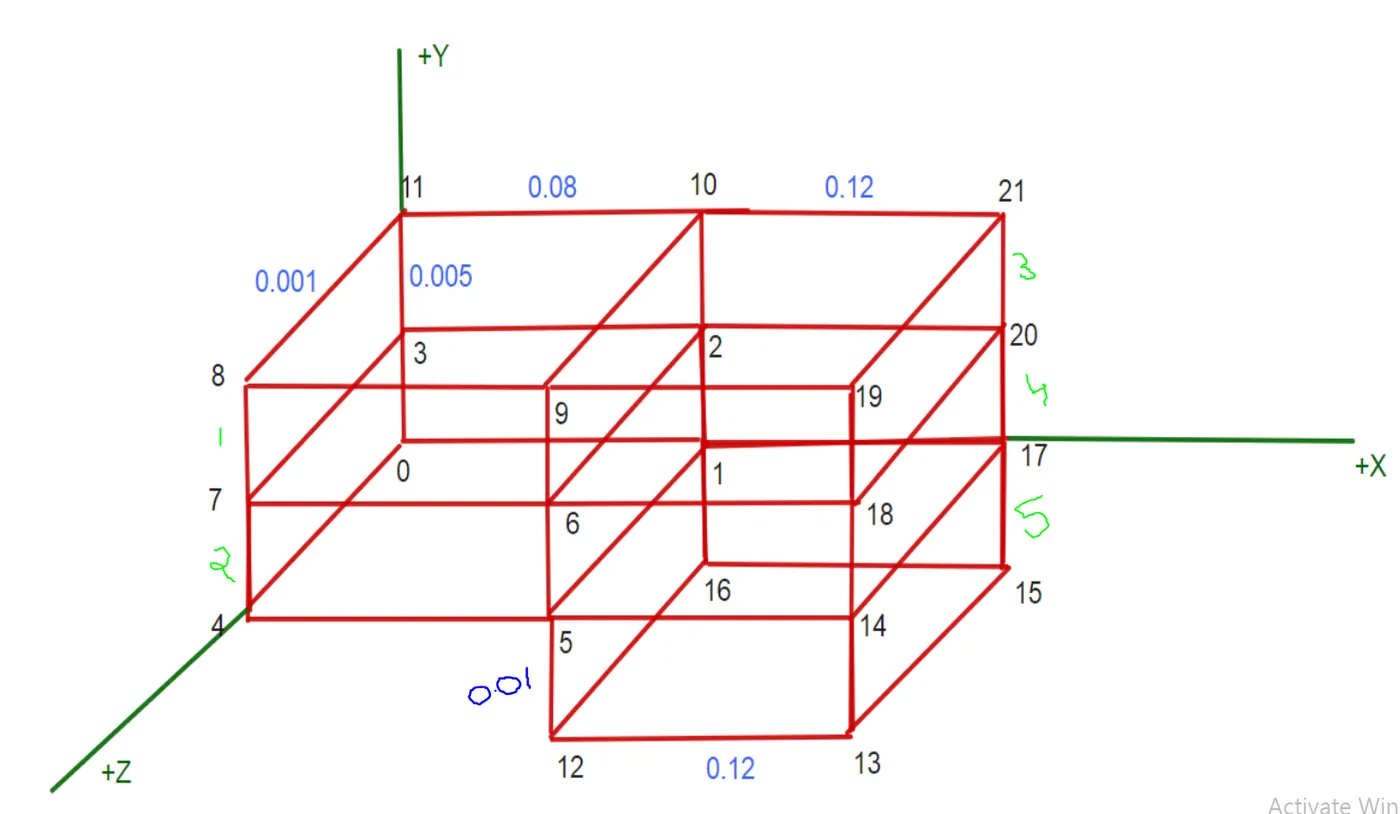
Actual Geometry & dimensions :

Mesh specifications :
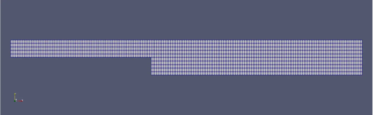
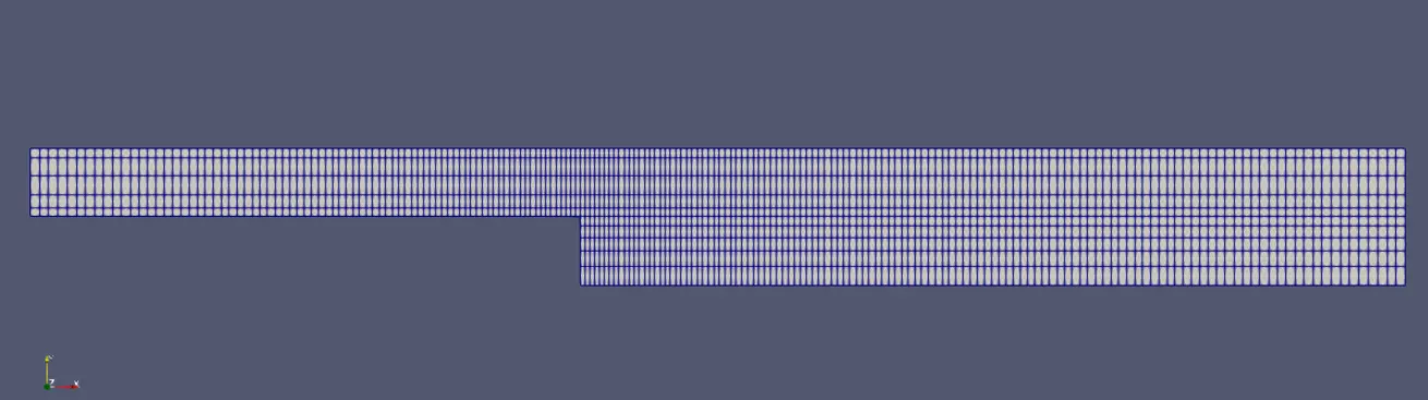
No of cells along the X direction = 200
No of cells along the Y direction = 10
Mesh grading factors = 0.2, 0.5, 0.8 and 1
Steps :
- open the terminal in the Linux operating system
- Type 'cd $FOAM_TUTORIALS' and it navigates to the inbuilt Tutorial files of the open foam software.
- Type 'cd incompressible' and it navigates through the incompressible folder in tutorials folder.
- Type 'cd icoFoam' and then type 'ls' it shows the contents of icoFoam folder.
- As it is a cavity based simulation problem the cavity file is copied from the main tutorial and pasted in the run directory .
- The simulation should not be run directly from the Tutorail folder as it crashes the default tutorials so we have to re install openfoam again inorder to get back the tutorials again.
- Type 'cp -r cavity/ $FOAM_RUN /cavity_test' it copies the tutorial cavity files to run directory and it saves the original file as 'cavity test'.
- Type 'cd system' which opens the system folder in the cavity folder.
- Type 'gedit blockMeshDict' which edits the geometry and save the geometry.
- Similarly type 'gedit controlDict' which opens the control dict file where the values of start time and end time values are given and the time step is choosen carefully according to courents criteria . i.e courants number should be less than 1 other the solution will never converge and blows up and the software automatically stops the simulation
- Type 'cd ..' which moves the folder one step back and type 'cd 0' which navigates through the initial boundary conditions folder i.e at time t=0sec and there type 'gedit p' and 'gedit U' to edit the pressure and velocity boundary conditions.
- After editing type 'cd ..' which moves one step back and now type 'blockMesh' which generates the mesh as the polymesh folder in the constant folder.
- After mesh has been generated without any errors type 'checkMesh' to check the mesh.
- Now type the solver name i.e 'icoFoam' to run the simulation.
- After succesfull simulation type 'paraFoam' for the post processing.
BlockMeshDict file :
/*--------------------------------*- C++ -*----------------------------------*\
  =========                 |
  \\      /  F ield         | OpenFOAM: The Open Source CFD Toolbox
   \\    /   O peration     | Website:  https://openfoam.org
    \\  /    A nd           | Version:  8
     \\/     M anipulation  |
\*---------------------------------------------------------------------------*/
FoamFile
{
    version     2.0;
    format      ascii;
    class       dictionary;
    object      blockMeshDict;
}
// * * * * * * * * * * * * * * * * * * * * * * * * * * * * * * * * * * * * * //

convertToMeters 0.01;

vertices
(
    (0 0 0)//vertex 0
    (8 0 0)//vertex 1
    (8 0.6 0)// vertex 2
    (0 0.6 0)// vertex 3
    (0 0 0.1)// vertex 4
    (8 0 0.1)//vertex 5
    (8 0.6 0.1)//vertex 6
    (0 0.6 0.1)//vertex 7
    (0 1 0.1)//vertex 8
    (8 1 0.1)//vertex 9
    (8 1 0)//vertex 10
    (0 1 0)//vertex 11
    (8 -1 0.1)//vertex 12
    (20 -1 0.1)//vertex 13
    (20 0 0.1)//vertex 14
    (20 -1 0)//vertex 15
    (8 -1 0)//vertex 16
    (20 0 0)//vertex 17
    (20 0.6 0.1)//vertex 18
    (20 1 0.1)//vertex 19
    (20 0.6 0)//vertex 20
    (20 1 0)//vertex 21
);

blocks
(
    hex (0 1 2 3 4 5 6 7) (80 3 1) simpleGrading (1 1 1)//block 1
    hex (3 2 10 11 7 6 9 8) (80 2 1) simpleGrading (1 1 1)//block 2
    hex (2 20 21 10 6 18 19 9) (120 2 1) simpleGrading (1 1 1)//block 3
    hex (1 17 20 2 5 14 18 6) (120 3 1) simpleGrading (1 1 1)// block 4
    hex (16 15 17 1 12 13 14 5) (120 5 1) simpleGrading (1 1 1)//block 5
);

edges
(
);

boundary
(
    inlet
    {
        type patch;
        faces
        (
            (0 4 7 3)
            (3 7 8 11)
        );
    }
    outlet
    {
        type patch;
        faces
        (
            (18 20 21 19)
            (14 17 20 18)
            (13 15 17 14)
        );
    }
    frontAndBack
    {
        type empty;
        faces
        (
            (0 3 2 1)
            (4 5 6 7)
            (7 6 9 8)
            (3 11 10 2)
            (6 18 19 9)
            (2 10 21 20)
            (5 14 18 6)
            (1 2 20 17)
            (12 13 14 5)
            (16 1 17 15)
        );
    }
    fixedwalls
    {
        type wall;
        faces
        (
            (5 4 0 1)
            (8 9 10 11)
            (19 21 10 9)
            (15 13 12 16)
            (16 12 5 1)
        );
    }
);
mergePatchPairs
(
);

// ************************************************************************* // 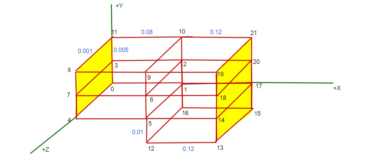
The fluid enters through the left shaded face and leaves the right shaded face.
Upper and bottom walls are fixed and the wall at the bottom of the step is also fixed.
ControlDict File :
/*--------------------------------*- C++ -*----------------------------------*
  =========                 |
  \      /  F ield         | OpenFOAM: The Open Source CFD Toolbox
   \    /   O peration     | Website:  https://openfoam.org
    \  /    A nd           | Version:  8
     \/     M anipulation  |
*---------------------------------------------------------------------------*/
FoamFile
{
    version     2.0;
    format      ascii;
    class       dictionary;
    location    "system";
    object      controlDict;
}
// * * * * * * * * * * * * * * * * * * * * * * * * * * * * * * * * * * * * * //

application     icoFoam;

startFrom       startTime;

startTime       0;

stopAt          endTime;

endTime         0.05;

deltaT          1e-5;

writeControl    timeStep;

writeInterval   20;

purgeWrite      0;

writeFormat     ascii;

writePrecision  6;

writeCompression off;

timeFormat      general;

timePrecision   6;

runTimeModifiable true;


// ************************************************************************* //
Pressure boundary conditions file :
/*--------------------------------*- C++ -*----------------------------------*
  =========                 |
  \      /  F ield         | OpenFOAM: The Open Source CFD Toolbox
   \    /   O peration     | Website:  https://openfoam.org
    \  /    A nd           | Version:  8
     \/     M anipulation  |
*---------------------------------------------------------------------------*/
FoamFile
{
    version     2.0;
    format      ascii;
    class       volScalarField;
    object      p;
}
// * * * * * * * * * * * * * * * * * * * * * * * * * * * * * * * * * * * * * //

dimensions      [0 2 -2 0 0 0 0];

internalField   uniform 0;

boundaryField
{
    inlet
    {
        type            zeroGradient;
    }

    outlet
    {
        type            fixedValue;
        value           uniform 0;
    }

    fixedwalls
    {
        type            zeroGradient;
    }

    frontAndBack
    {
        type            empty;
    }
}

// ************************************************************************* //
Velocity boundary conditions file :
/*--------------------------------*- C++ -*----------------------------------*
  =========                 |
  \      /  F ield         | OpenFOAM: The Open Source CFD Toolbox
   \    /   O peration     | Website:  https://openfoam.org
    \  /    A nd           | Version:  8
     \/     M anipulation  |
*---------------------------------------------------------------------------*/
FoamFile
{
    version     2.0;
    format      ascii;
    class       volVectorField;
    object      U;
}
// * * * * * * * * * * * * * * * * * * * * * * * * * * * * * * * * * * * * * //

dimensions      [0 1 -1 0 0 0 0];

internalField   uniform (0 0 0);

boundaryField
{
    inlet
    {
        type            fixedValue;
        value           uniform (2 0 0);
    }

    outlet
    {
        type            zeroGradient;
    }

    fixedwalls
    {
        type            noSlip;
    }

    frontAndBack
    {
        type            empty;
    }
}

// ************************************************************************* //
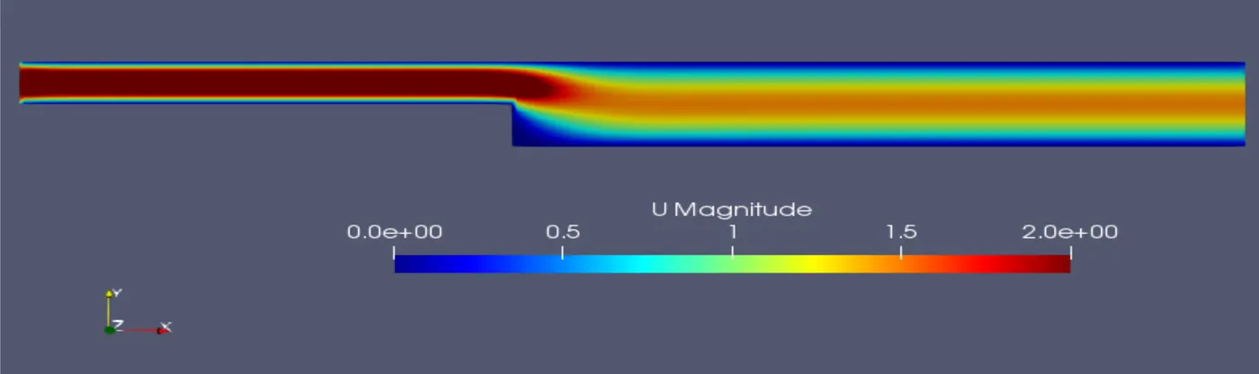
Inlet velocity in X direction = 2m/sec
Block mesh Grading factor :
It is a technique called mesh streching and grading factor values range from 1 to 10. A value of 1 produces most uniform Mesh transition. Increasing the value will reduce the number of elements and local Mesh quality which decreasing the value will increase the number of elements and local mesh quality.
f= size of end cell/size of starting cell
Results and discussion:
1) Mesh grading of 1 :
Mesh :
simulation :
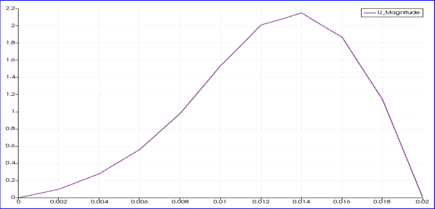
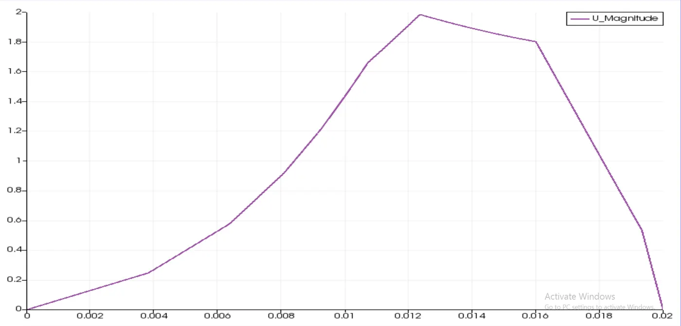
Velocity profile at a distance of 0.085 from the inlet :
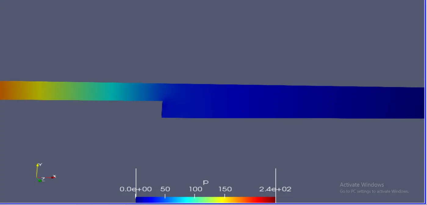
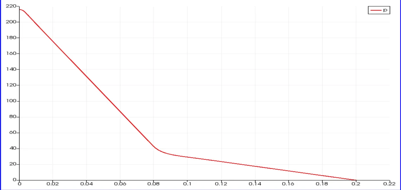
Pressure shows a little variation in y direction and hence the pressure variation in X direction is represented.
pressure simulation :
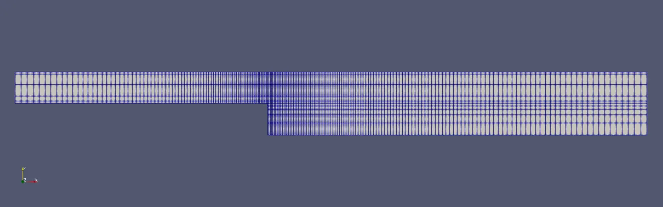
2) Mesh grading of 0.2 :
BlockmeshDict file Modification :

Mesh :
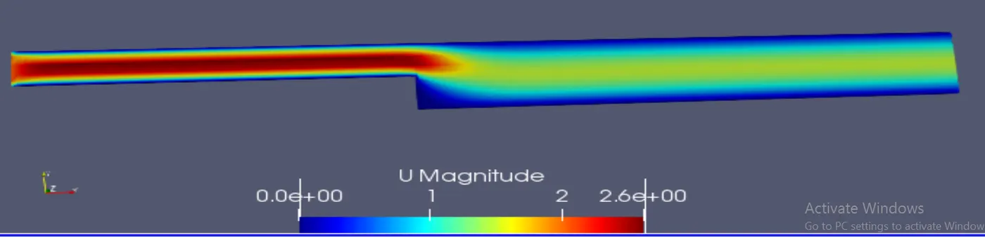
3) Mesh grading of 0.5 :
BlockmeshDict file Modification :

Mesh :
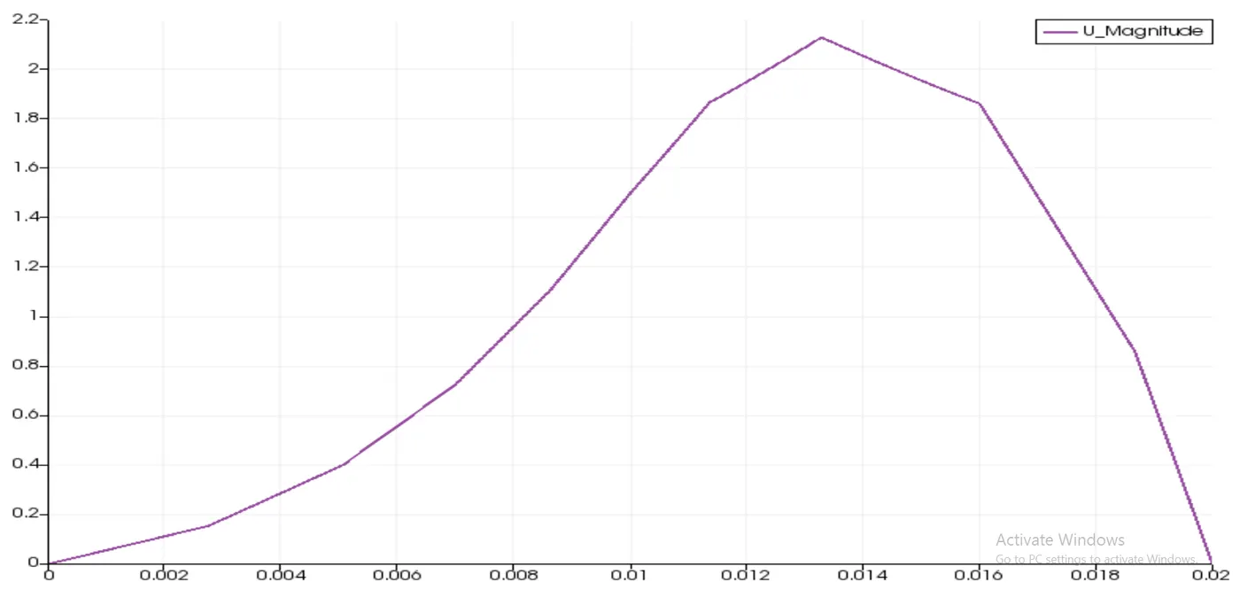
velocity simulation :
4) Mesh grading of 0.8 :
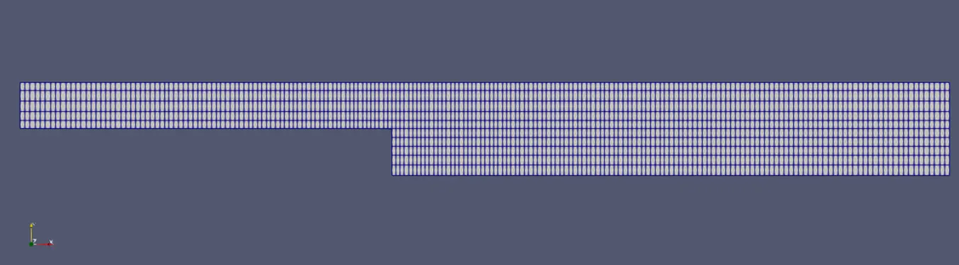
blockmeshdict file modification :

mesh :
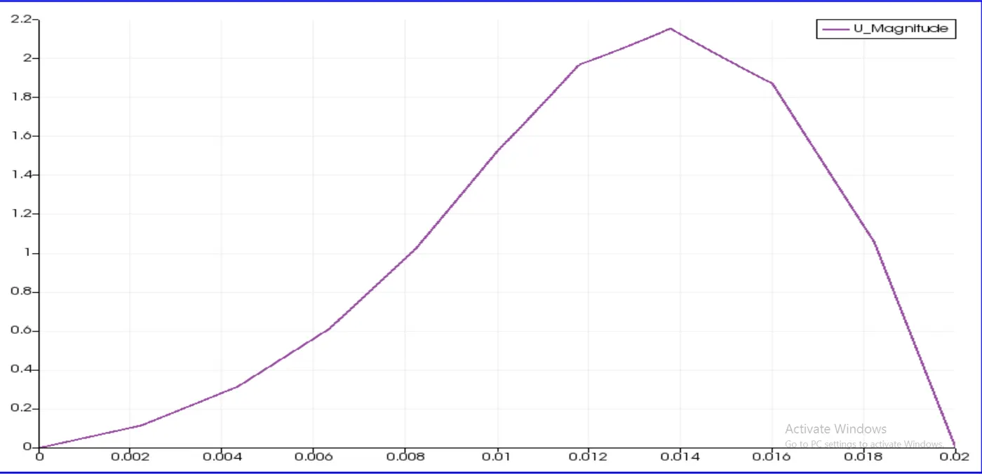
Velocity simulation :

Comparisons and Observations :
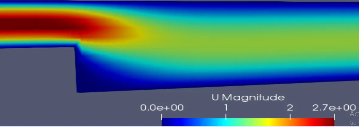
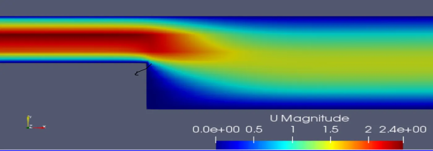
At the step :
1 grading
0.2 grading :
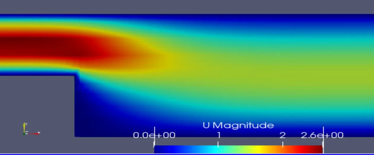
0.5 grading :
0.8 grading :
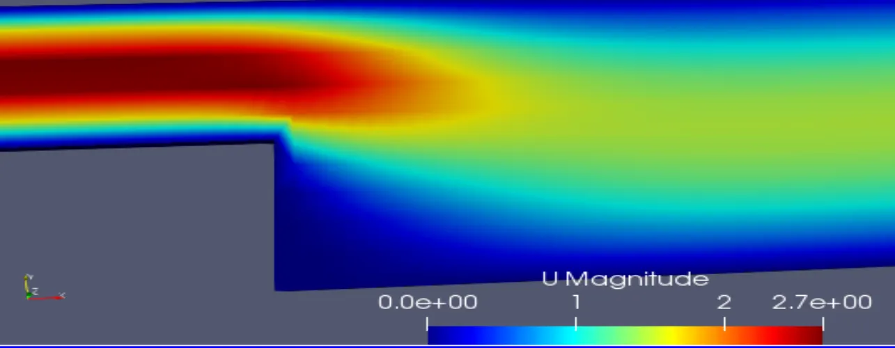
If we observe carefully at the step for different grading factor the profile is different and the best accuarte result for the step is given by the grading factor 0.2 .
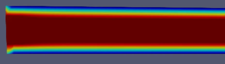
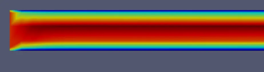
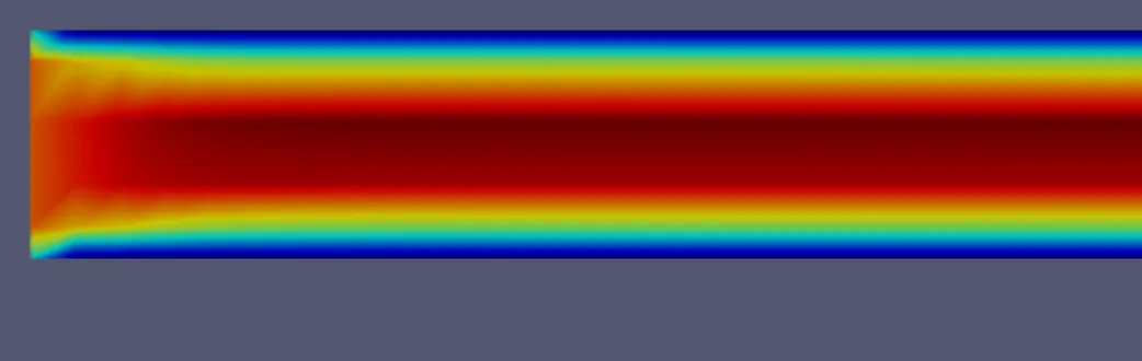
At the Inlet :
1 grading factor :
0.2 grading factor :
0.5 grading factor :
0.8 grading factor :
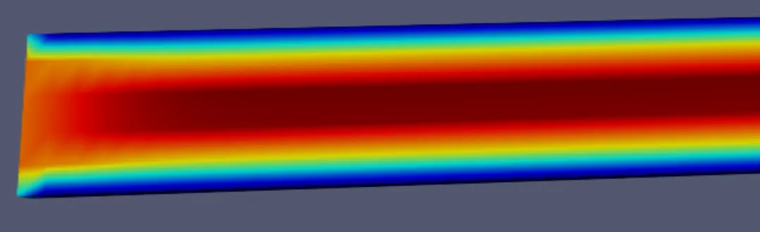
From the above comparisons it is clear that the accurate profile for the velocity at inlet is best given by the grading factor 1.
Conclusions :
- There is an effect on simulation by the grading factors which is better observed in the turbulence models
- The Maximum velocity value is changed by the grading factors i.e different maximum value is obtained at different grading factor and the value lies between 0.13 and 0.14.
- Low grading factor is used for the analysis at the step
- Higher grading factor is used for the analysis at the inlet.