Bird Strike - Project - 2
Objective
To perform a simulation of bird strike in aero engine using LS-Dyna and satisfying all the required outputs asked for the project.
- To prepare a main file for the simulation that include all the reference cards.
- Assign material, sections, boundary conditions and other required inputs to the parts.
- Follow a consistent numbering approach 100000+ for nodes, 500000+ for elements, and 1000+ for the parts. All other keywords should be numbered within 10000-19999 while following a range for each one.
- Describing the simulation results.
Procedure
- The given .k file was opened in Ls-PrePost and it contained lots of parts. From the objective, it was said that there should be a main file that contains only references. So each part was saved separately and created new .k file for all the other references required.
- The unit system used for this project is in kg, mm, ms.
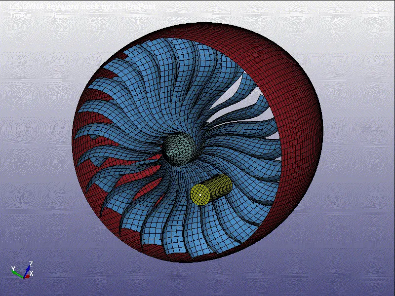
Bird
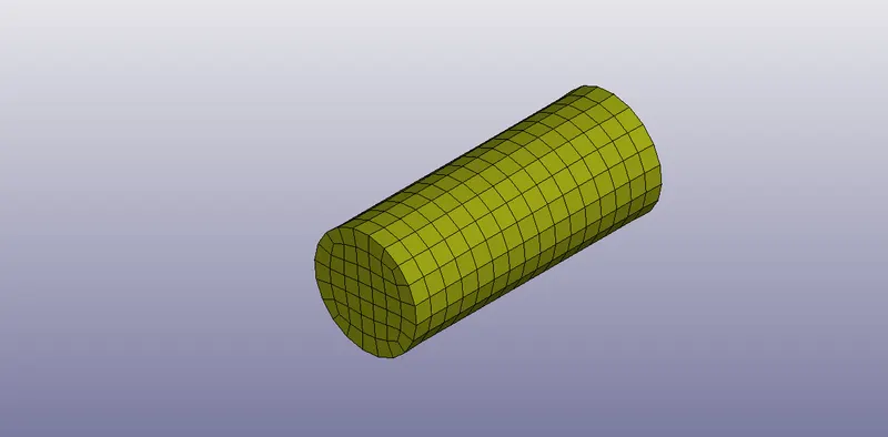
- The above picture depicts a bird-like model that was used while doing this simulation. Here a material card and a section card were created and then added to the part-id.
- Section card was created using section>shell where the value for the thickness was assigned to it.
- From some literature studies, It was seen that the bird was modeled with a material similar to that of skin tissue. So the properties corresponding to those values were assigned to the material card. Also, a youngs modus of 2GPa was assigned.
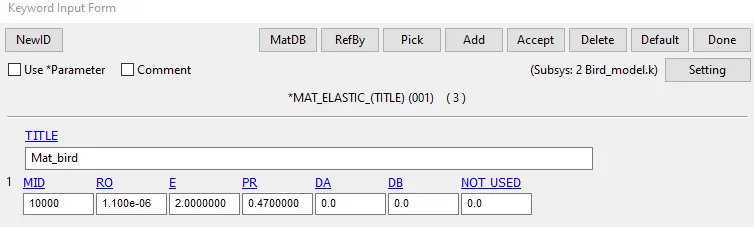
- Since the bird hits the blade, a velocity of 70mm/ms was assigned to the bird model using the *Initial>Velocity_Generation card.
Blade
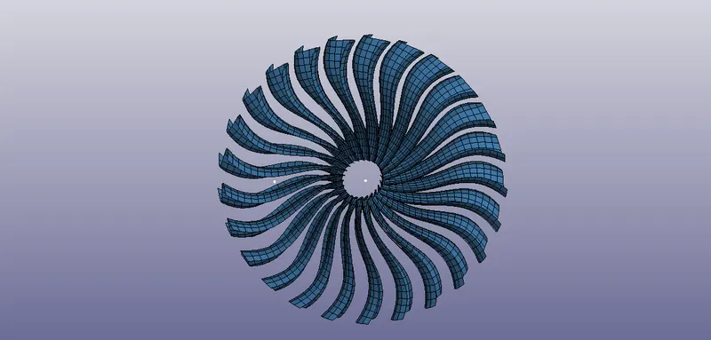
- A section card was created for the blade using section>shell and assigned the thickness.
- Generally, Titanium alloys material are used to model the blade part. Here a material card was provided as a given data that corresponds to the material data for the blade.
- A curve was defined for material modeling where it is assigned to LCSS in the material card.
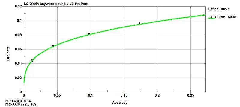
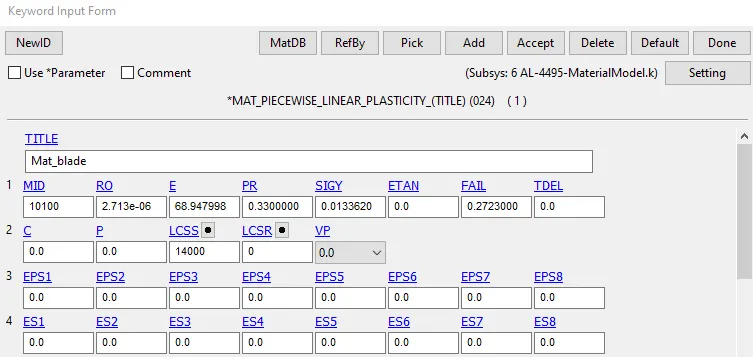
- The section and the material card were finally assigned to the part id.
- The blades are having a rotational motion and a rotational velocity was assigned to the blade using the Initial>Velocity-Generation.
Casing
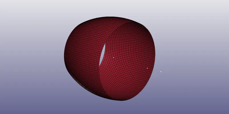
- A section card was created for the blade using section>shell and assigned the thickness.
- Here the material properties of carbon steels were used to model the casing of the fan and the values for density, youngs modulus, and Poisson's ratio were assigned in the material card.
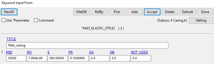
- Finally, these section and material cards were assigned to the part id.
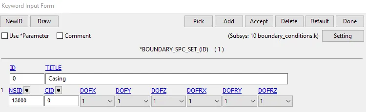
- Here the casing should be constrained in all degrees of freedom and this was done using the SPC_SET option.
Hub
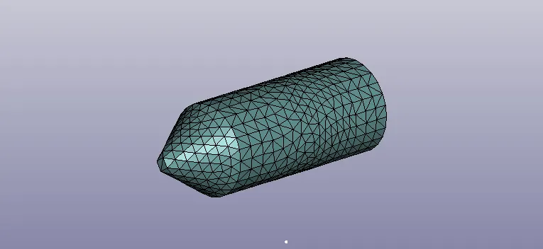
- A section card was created for the hub part using section>soild with an ELFORM of 1.
- Here also the material properties of carbon steels were used to model the hub and the values for density, youngs modulus, and Poisson's ratio were assigned in the material card.
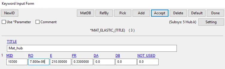
- After that, the section and material cards were assigned to the part id.
Contact definition
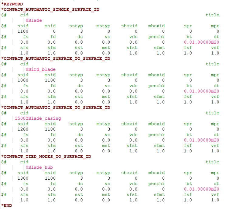
- *AUTOMATIC_SINGLE_SURFACE contact card was defined for the blades to avoid self penetration by defining the slave set which corresponds to the blade.
- *AUTOMATIC_SURFACE_TO_SURFACE contact card was used while describing the contact with the blade and the casing. There may be a chance that due to the bird strike the blades may get broken and penetrate through the casing. To avoid that this contact was given by assigning the slave and master set accordingly. One more contact of this similar type was added to define the contact between the bird and the blade to fix the penetration issue when the bird hits the blade.
- *TIED_NODE_TO_SURFACE contact cards were used to define the contact between the blades and the hub. In tied contact types, the slave nodes are constrained to move with the master surface. Here the blades were taken as the master and the hub as slave type.
Control cards
- *CONTROL_ENERGY card was used which gives the hourglass energy for the part by assigning the HGEN value of 2.
- *CONTROL_TERMINATION_CARD from keyword manager was used to define the simulation time using the ENDTIME option.
Database.
- The output data needed for the analysis is generated using a *DATABASE card.
- DATABASE_BINARY_D3PLOT under keyword manager ensures d3plot files are written in which it stores the stress-strain contours of the deformed system.
- ASCII under keyword manager can generate different output such as force generated in a contact, total energy, material energy, etc. Here output for ELOUT, GLSTAT, MATSUM, RCFORCE, NODOUT, SLEOUT, is been requested.
- NODOUT- Nodal point data.
ELOUT-Element data.
GLSTAT- Global data.
MATSUM- Material energies.
RCFORC- Resultant interface forces.
SLEOUT- Set dt for sliding interface energy. - DT (Time interval between the output) is an essential parameter that basically denotes the time interval after which the state of solution needs to be written and the value is kept as 0.1 for this analysis.
- *DATABASE_HISTORY_NODE card was also created to get the acceleration plot for a node.
- *DATABASE_EXTENT_BINARY card was provided by specifying STRFLG which writes strain tensor data to d3plot and ELOUT.
Renumbering
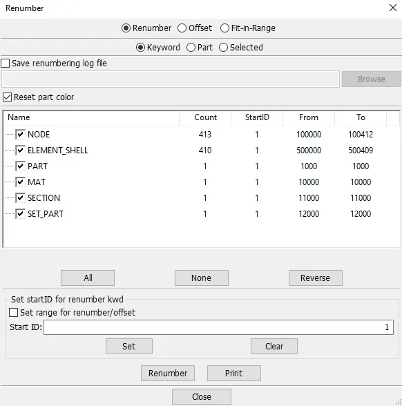
- The main file contains lots of reference cards which may show errors if the numbering of the parameters is the same. Also, it's a good practice to arrange each of them in a proper manner so that we may find it easy while giving a check. So here each part was renumbered as per the given objective.
- Renumbering can be done using Model and part>Renumber>Select the one which needs to be renumbered>Give a start ID>Set>Renumber.
- One of the parts renumbered is shown below.
Model check-up and running the simulation.
- The model is checked for any errors and if any error occurs it should be corrected further.
- The .k file is been saved and ran using LS-DYNA manager.
Results
- An explicit simulation was done for the bird strike project and satisfied all the objectives. Some of the output from the simulation are discussed below.
Effective stress
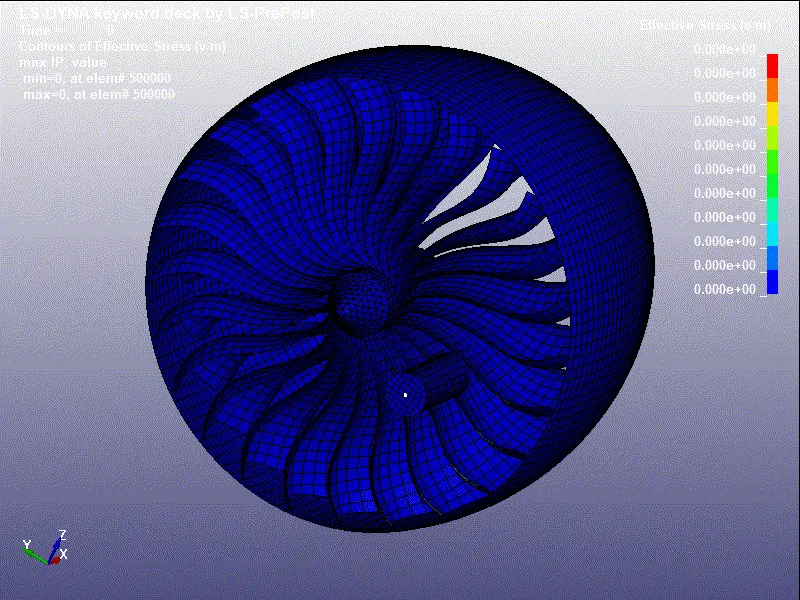
- The above gif shows effective stress. Its seen that there a high-stress concentration around some blade regions when the bird strikes the blade. Also, there is some stress shown in the simulation before the collision happens between the blade and the bird. It may be due to the contact that we defined between the two parts.
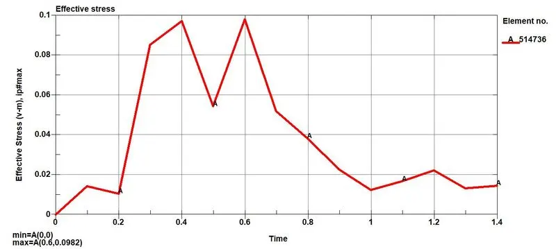
- The above graph depicts the effective stress for element 514736 which belongs to the blade part. The maximum effective stress observed is 0.0982Gpa which is more than the yield stress of the blade material. So we can see a plastic deformation here.
Effective plastic strain
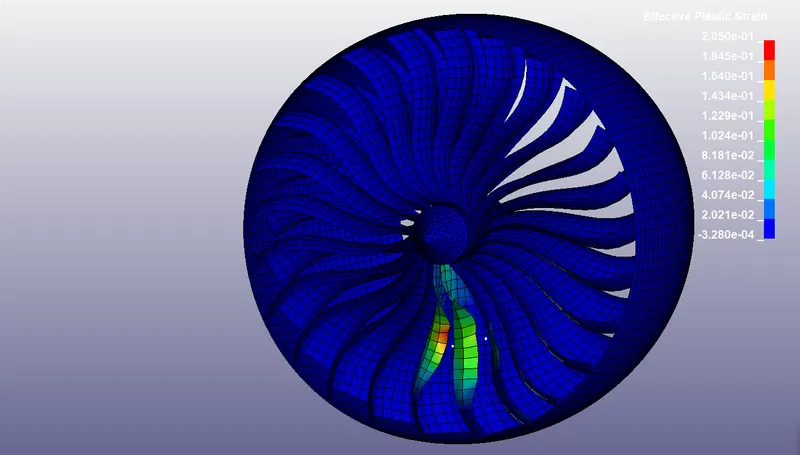
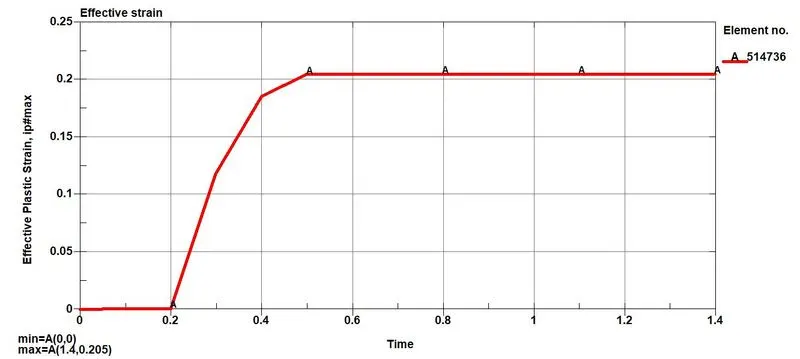
- The plot above shows the effective plastic strain values for the blade element number 514736. It observed that there is no strain till 0.2ms and when the bird strikes the blade, the strain increases, and a plastic deformation happens and afterward the strain remains constant. The maximum plastic strain was found to be 0.205.
Resultant acceleration
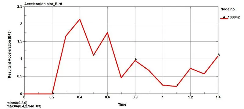
- The resultant acceleration associated with the bird with node id 100042 is shown above. The acceleration remains zero since the bird was moving with a constant velocity of 70mm/ms and when the bird strikes the blade the velocity drops and thus the acceleration varies. The maximum value for the resultant acceleration was found to be 2.14e03mm/ms2.
The rotational velocity of the blade about the x-axis
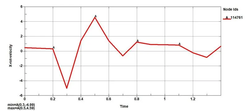
- The rotational velocity associated with the blade with a node id 114761 is shown above. The blade initially rotates almost at a constant velocity, But when the strikes happen between the bird and the blade the rotational velocity drops for some time and then increases. There is a function happening and it attains a constant value after some time. Here since we have given the termination time of 1.4ms, the further curve for this plot cant be observed here.
Energy plot
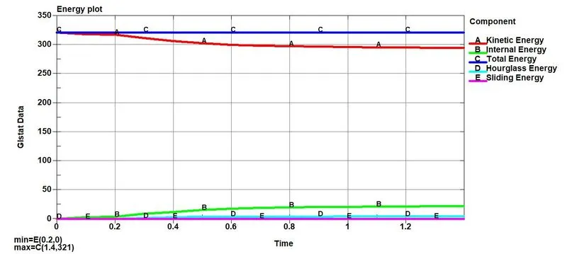
- The global energy plot for the bird strike model is shown above.
- The plot for the Kinetic energy is constant for some time and when the bird strikes the blade, it deaccelerates and the kinetic energy decreases which is shown by a decline curve in the plot.
- The internal energy a steep increase after the strike happens. Here the kinetic energy has been stored as internal energy following the law of conservation of energy theory.
- Total energy remains constant.
- Hourglassing is a state of strain, which is free of energy (ZEM: Zero Energy Mode) and can emerge in the case of one-point-integrated solid- (hexahedrons) and shell elements. Hourglass modes are mostly caused by concentrated loads and contact (contact force at several nodes ). Hourglassing can be reduced by refining the mesh, Using a fully integrated element type, etc. but takes more computation time when a fully integrated element type is used.
- Here the hourglass energy is very small and is kept within the range.
- Sliding energy (GLSTAT - global) says about the numerical validity of the contacts. If friction is zero, then the GLSTAT value should be 1% or less of the internal energy. Since there is no sliding occurring, the value of sliding energy is equal to zero.
Conclusion
- Performed a simulation of bird strike in aero engine using LS-Dyna and satisfied all the required outputs asked for the project.
- Total run time for this analysis was shown more than 2 hours therefore mass scaling was used initially to run the model which reduced the time to 4 minutes which made faster to interpret the post processing results and to find out errors. When mass scaling was used it effect the inertia due to increase in mass which effects the result. Normally a mass scaling with 8% increase in mass can be used. Here for an accurate result the simulation was ran normally without mass scaling.
............................................................................
File: https://drive.google.com/folderview?id=1ja2tCeiKimC9bmkD8ctJvUyA34xnpb9j