Bird Strike - Project - 2
Aim: To simulate the scenario of Bird Strike in Aero-Engine, by using proper flow of the keyword file and calling all the relevant files to the main.k file.
Procedure:
1. The bird strike file was loaded into the ls prepost.
2. Each parts were seperated in seperate.k files.
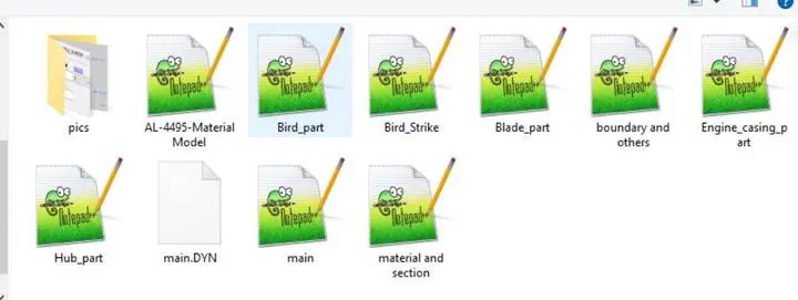
3. A main.k file is defined where all the keyword files are called.
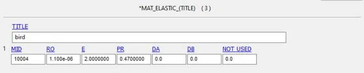
4. The material and section are defined and saved in the material and section file and there the provided aluminium material of the blade is also called so that that can be called together in the main file together.
The provided material is used for the blade with the LCID mentioned.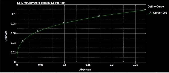
Fig: Define curve used in the blade material
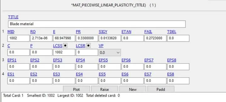
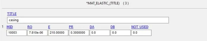
For the bird and the other parts Elastic material card is called and the following data is provided.
For the casing and the hub, steel property was given as shown below

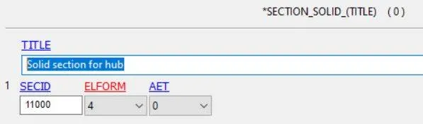
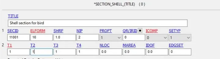
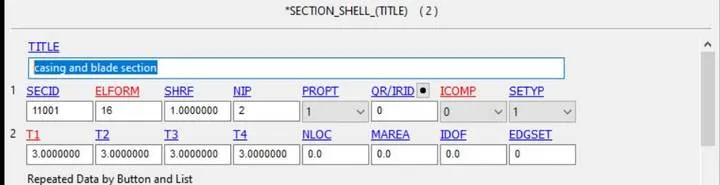
Section solid was provided for hub where as section shell with elform 16 was assigned for the other parts with shell thickness of 1 for bird and shell thickness of 3 for casing and blades and after assigning , Part card was design for the above mentioned parts with their respective properties.
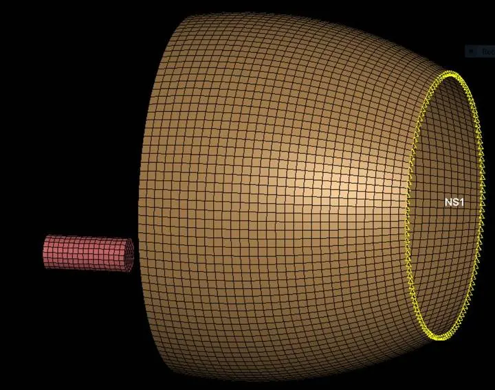
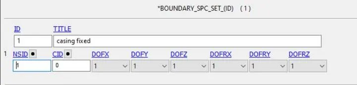
Now as we would want our casing to be fixed so we create a node set at one end of the casing used spc boundary to fix in all direction.
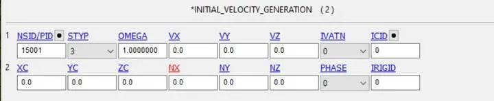
Now , As the bird would be hitting the blade, motion has to be provided to the bird, Initail velocity generation is used and the bird is selected as the part set id and velocity of 200 mm/ms is assigned. (relative velocity data from google)
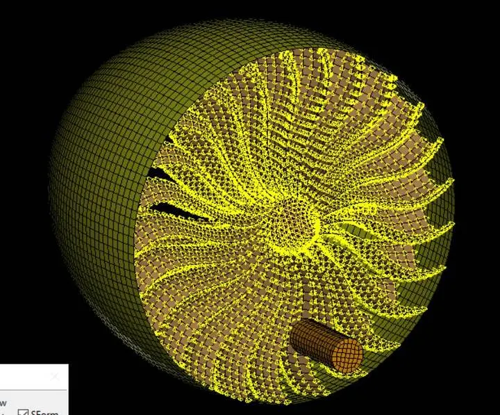
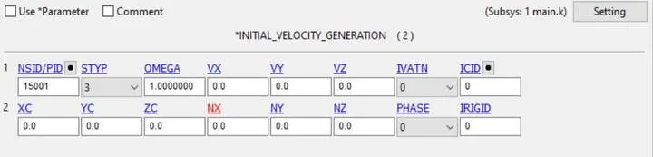
a nodeset is defined which includes the hub and the blade part together and this node set Id I used in initial velocity generation with angular velocity 0.5 rad/ms
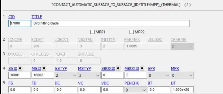
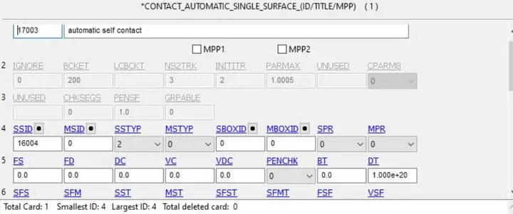
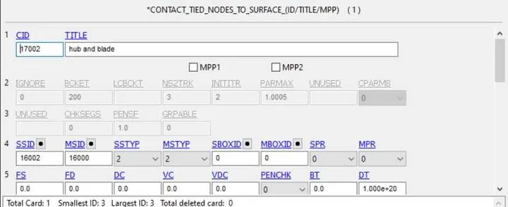
Now , 3 contacts are defined:
1. Automatic surface to surface- Bird and blade, with blade being the master and bird being the slave.
2. Automatic Single surface
3. Tied node to surface- To define that the hub and the blade are in contact
Now , Control termination of dt 2ms is given , database extent binary with strflg 1 is defined, d3plot- dt 0.05,
GLstat and matsum ascii with dt -0.05 are defined.
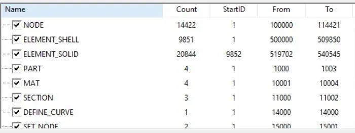
Renumbering is done as per mentioned in the question
Now the model was run, but without mass calling it was showing a large running time of 40 mins, so Control time step was defined with many trial and error was done with dt2ms values and finally a efficient mass increase % of 10% with clock time 6 minutes was found with dt2ms : -2.7E-04.
All the other trial method strategy is mentioned below:
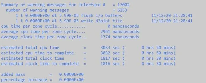


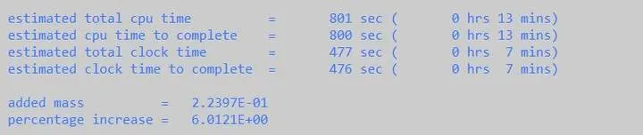
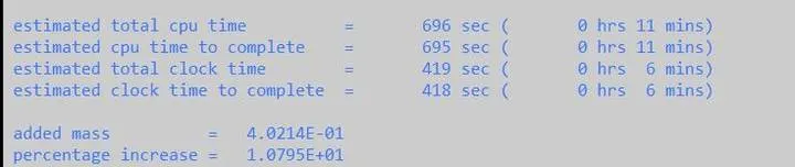
Thus the above mentioned mass scaling trial was finalized.

Now the simulation was run and the post processing was done. The simulation video is attached with the files.
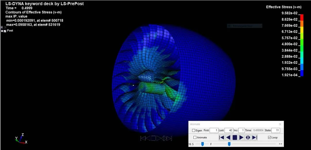
Fig: Effective stress at the point of impact
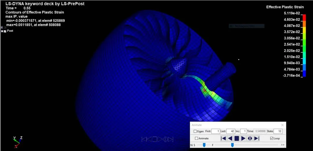
Fig: effective plastic strain in the blade element at the point of impact
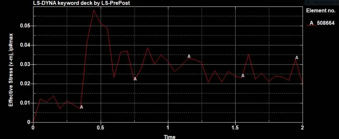
Fig: Effective stress plot of an element in the blade part where the bird strikes.
We can see her after the time of point of contact, the stress recieves a spike in the blade element.
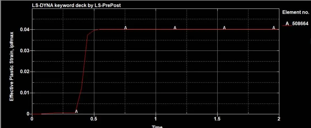
Fig: plastic deformation in the blade element at the point of impact.
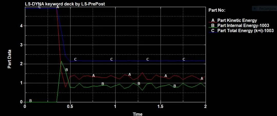 Fig :Bird part energy plot.
Conclusion: We can see that after the point of impact as expected , the Kinetic energy of the bird starts to decrease and the internal energy starts increasing, the total energy then remains constant.
the simulation was run successfully, and we learnt how to manage all the files separately when such projects are done, and contact and boundary conditions to be implemented according to the simulation was learnt.
N.B- all the files are attached in Zip with the submission.