Bending Analysis on three types of beams(Rectangular beam, I -section beam, and C-section beam) using Solidworks FEA and suggesting the best out of the three
ABSTRACT
In this project, the main objective is to compare the bending performance of the three types of beams(Rectangular beam, I -section beam, and C-section beam) which is extruded to a length of 400mm. After which, a baseline simulation is run on these beams at an external force of 1500N acting upon their smaller face and compare the results of stress, displacement, and strain for all the three beams and suggest the best out of the three.
INTRODUCTION
- FEA(Finite Element Analysis)
FEA is an analysis method using FEM(Finite Element Method) to solve the structural problems. The finite element method is a numerical technique for obtaining an approximate solution to a wide variety of engineering problem. The method originated in the aerospace industry as a tool to study stresses in the complex air-frame structure.
Since its birth, the finite element method has gone through various developmental stages. Started with the formulation of finite element theory, variational and Galerkin's approaches for two dimensional and three-dimensional problems were formulated. Isoparametric formulations for both linear and non-linear, static and dynamic analysis were developed. Also, computational methods required by the finite element method were established. This method includes numerical integration of element equations, a solution of the global system of algebraic equations, study of numerical stability and error analysis solution algorithms.
- Stress:
When a body is acted upon by an external force or load, internal resisting force is set up, such a body is said to be in a state of stress, hence stress is the resistance offered by the body to deformation.
- strain:
when a force or load acts on a body it undergoes deformation. This deformation per unit length is known as unit strain or simply strain.
- Stress-Strain Curve:
To determine the relation between the stress and strain for a given material, let’s conduct an experiment. Take a test cylinder or wire and stretch it by an applied force. Record the fraction change in length (strain) and the applied force needed to cause the strain. Increase the applied force gradually, in steps, and record the readings.
Now, plot a graph between the stress (which is equal in magnitude to the applied force per unit area) and the strain produced. The graph for a typical metal looks as follows:
From the figure, we can see that in the region between O and A, the curve is linear. Hence, Hooke’s Law obeys in this region. In the region from A to B, the stress and strain are not proportional. However, if we remove the load, the body returns to its original dimension.
The point B in the curve is the Yield Point or the elastic limit and the corresponding stress is the Yield Strength (Sy) of the material. Once the load is increased further, the stress starting exceeding the Yield Strength. This means that the strain increases rapidly even for a small change in the stress.
This is shown in the region from B to D in the curve. If the load is removed at, say a point C between B and D, the body does not regain its original dimension. Hence, even when the stress is zero, the strain is not zero and the deformation is called plastic deformation.
Further, point D is the ultimate tensile strength (Su) of the material. Hence, if any additional strain is produced beyond this point, a fracture can occur (point E). If,
- The ultimate strength and fracture points are close to each other (points D and E), then the material is brittle.
- The ultimate strength and fracture points are far apart (points D and E), then the material is ductile.
TOOL USED
Solidworks Simulation Model(The version used in this project is SW2017)
Boundary conditions (Same for all 3 profiles):
Beam type = Cantilever Beam
Material = Alloy Steel
Bending load = 1500 N (on the shorter side of the profile)
PROCEDURE
2D model of the beams:
- RECTANGULAR SECTION
- I-SECTION BEAM
- C-SECTION BEAM
CASE 1(RECTANGULAR SECTION BEAM)
- Length of the above beams is 400mm.
- Alloy steel used for this analysis.
- Linear static analysis done for the beams.
- 5mm mesh used.
- Load applied for all the beams is 1500N on smaller face of beam(45mm for case1)
RESULTS
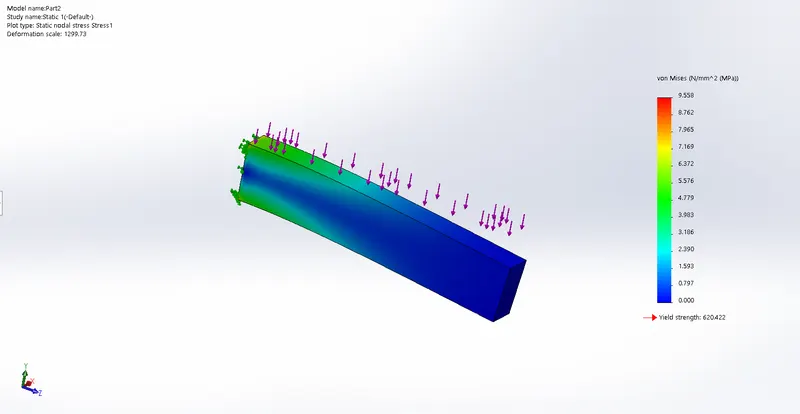
- STRESS
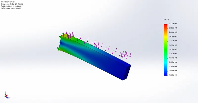
- STRAIN
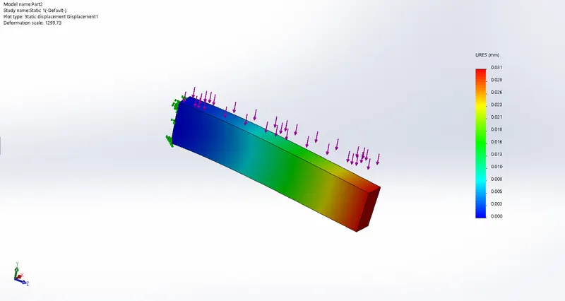
- DISPLACEMENT
- COMPARISION OF STRESS STRAIN AND DISPLACEMENT
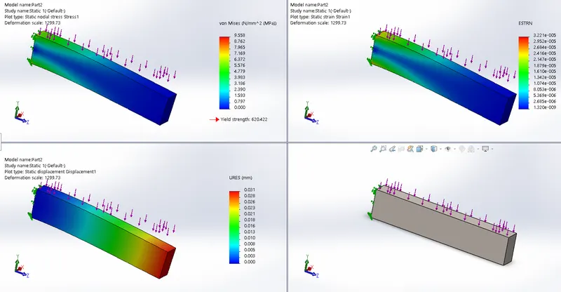
- DISPLACEMENT-(MAX- 0.031)
(MIN-0.000)
- STRAIN-(MAX-3.221e-005)
(MIN-1.320e-009)
- STRESS-(MAX-9.558 N/mm^2)
(MIN-0.00N/mm^2)
- Yield Strength(620Mpa)
CASE 2(I-SECTION BEAM)
- Length of the above beams is 400mm.
- Alloy steel used for this analysis.
- Linear static analysis done for the beams.
- 5mm mesh used.
- Load applied for all the beams is 1500N on smaller face of beam(40mm for case2)
RESULTS
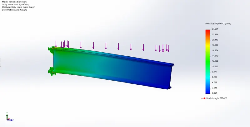
- STRESS
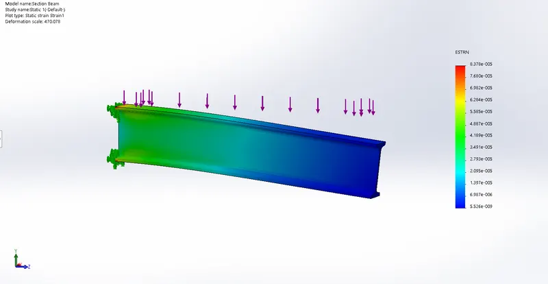
- STRAIN
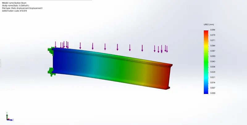
- DISPLACEMENT
- COMPARISION 0F STRESS STRAIN AND DISPLACEMENT
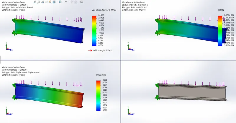
- DISPLACEMENT-(MAX- 0.086)
(MIN-0.000)
- STRAIN-(MAX-8.378e-005)
(MIN-5.526e-009)
- STRESS-(MAX-24.531 N/mm^2)
(MIN-0.00N/mm^2)
- Yield Strength(620Mpa)
CASE 3(C-SECTION BEAM)
- Length of the above beams is 400mm.
- Alloy steel used for this analysis.
- Linear static analysis done for the beams.
- 5mm mesh used.
- Load applied for all the beams is 1500N on smaller face of beam(45mm for case3)
RESULTS
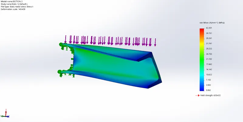
- STRESS
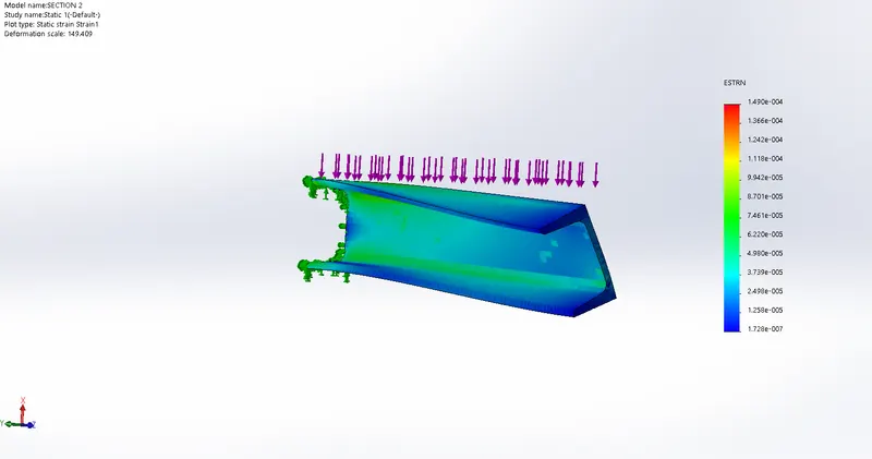
- STRAIN
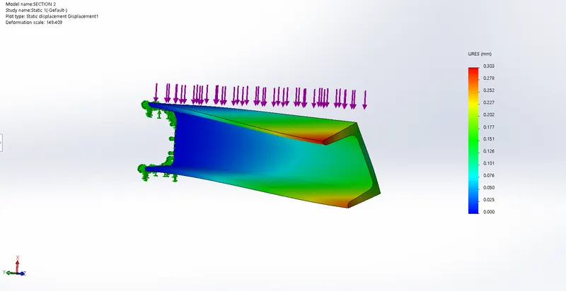
- DISPLACEMENT
- COMPARISION 0F STRESS STRAIN AND DISPLACEMENT
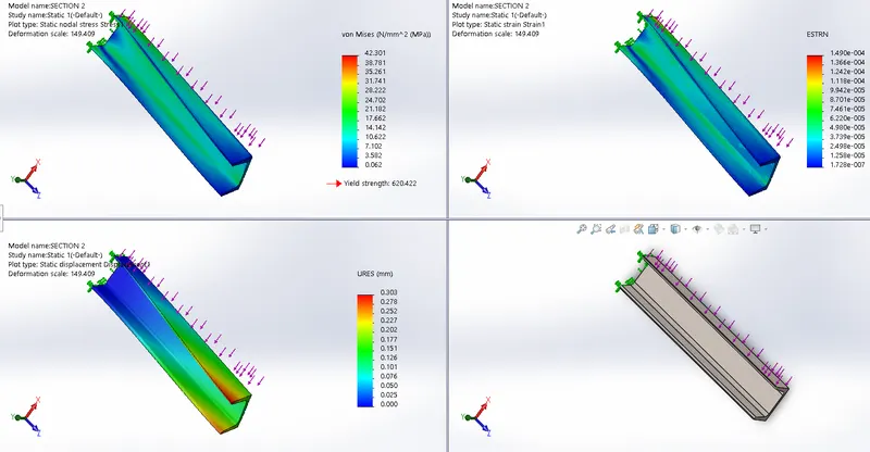
- DISPLACEMENT-(MAX- 0.303mm)
(MIN-0.000mm)
- STRAIN-(MAX-1.490e-004)
(MIN-1.728e-007)
- STRESS-(MAX-42.301 N/mm^2)
(MIN-0.62N/mm^2)
- Yield Strength(620Mpa)
CONCLUSION
The maximum Displacement Shown by the rectangular Beam is less as compared to the I-Section Beam and C section Beam,the Factor of Safety is also good as compared to the other two,However, it is the heaviest in terms of mass by a factor or 3X-5X compared to other beams. If the end application is conscious of the weight of the structure and needs the most structural integrity with the least weight, the I-beam is the best option.m and C-Section Beam,