BAJA SAE ATV Complete Design using CATIA V5
1. BAJA SAE ATV :
All-terrain Vehicle:
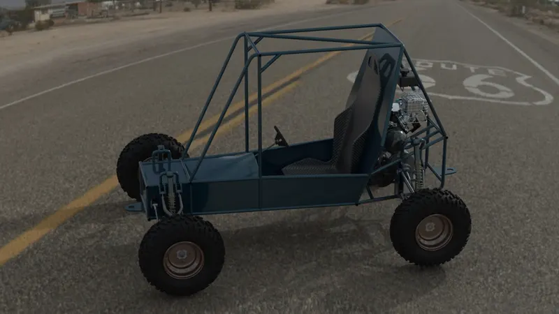
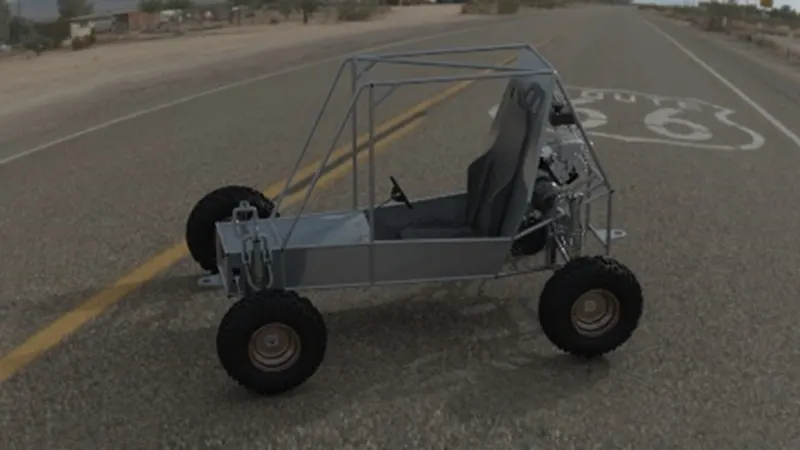
An all-terrain vehicle is one such vehicle that can handle all types of situations that includes, rain, muddy road, off-road, hill climbing, etc…This project focuses on developing an all-terrain vehicle by following the standard published by BAJA SAE India 2020.
BAJA SAE competition:
BAJA SAE is a multi-team completion in which each team prepare their own design to showcase their talents for better design prospects. Our ATV is one such vehicle. ATV will be designed as per the guidelines given in the document.
2. Tools used:
- Catia v5 is used as the designing tool. Catia V5 is a 3d modelling tool that is used extensively for the design of automotive parts and elements.
- Solidworks Visualize is used for rendering purpose. This tool is recommended for simple renders.
3. Design Procedure:
- Roll cage design
- Seat design
- Front-wheel assembly
- Rear wheel design
- Gear box design and positioning
- Rear wheel support frames design
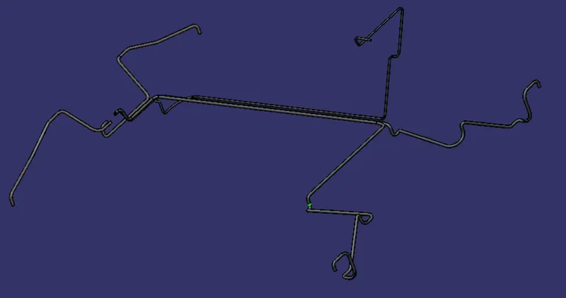
- Braking cables and acceleration cables design.
- Brake and acceleration pedals.
3.1.Roll Cage Design:
Roll cage is the frame that contains the entire strength of the ATV body. It is the crucial element of the construction of the ATV. The design requirement of the roll cage are taken from the BAJA SAE 2020 rulebook. The ends of the roll cages are welded together to form a strong joint. The Size of the pipe used is 25.4mm diameter with 3 mm thickness.
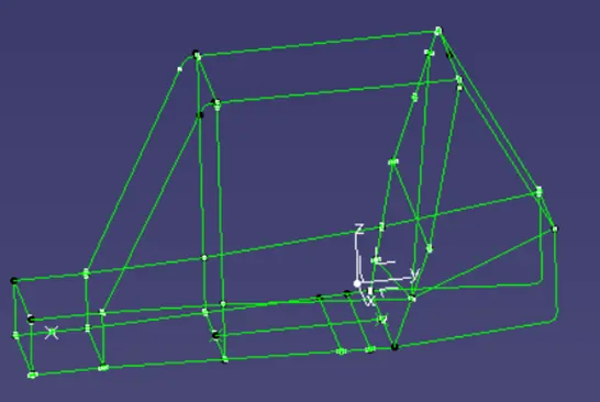
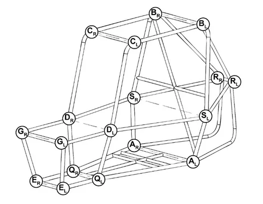
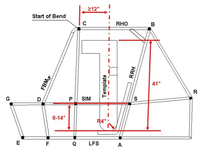
The images for the naming of different elements are shown below.
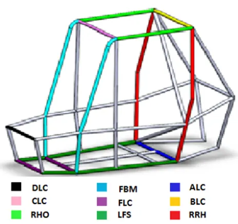
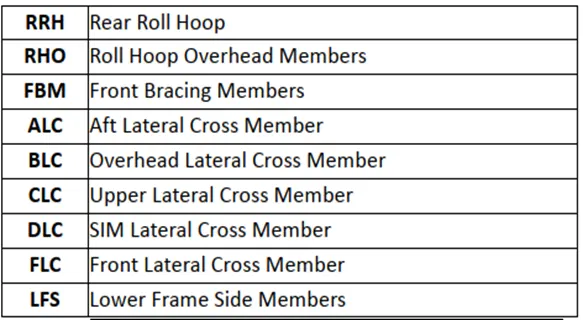
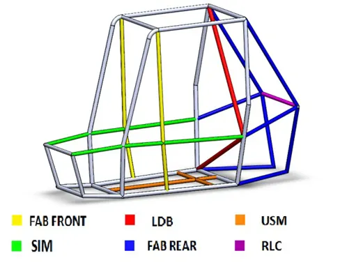
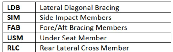
3.1.1 Lateral Cross members:
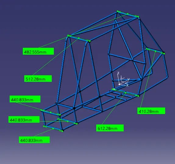
All lateral Cross members should be more than 203.5 mm (8 inch) of length.
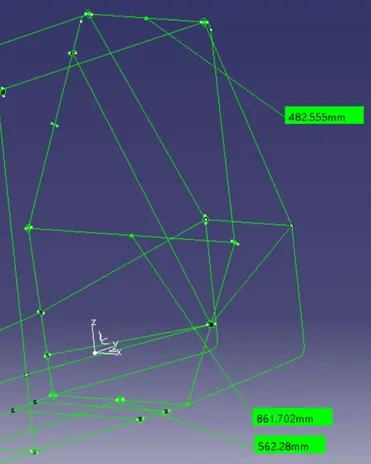
3.1.2. RRH- Rear roll hoop:
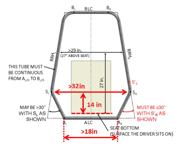
The rear roll hoop is designed as the following figure.
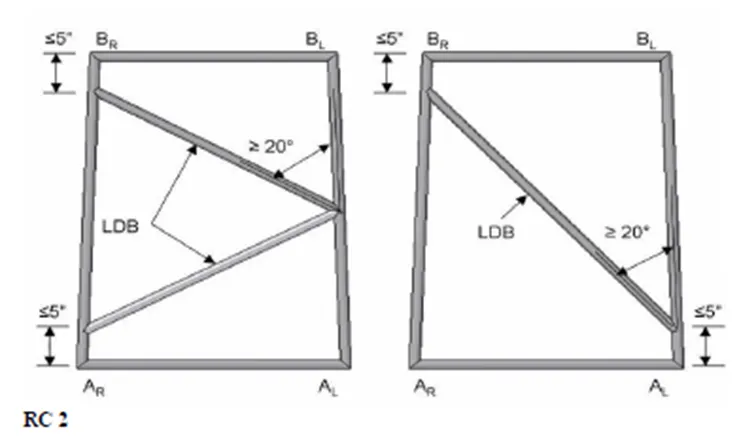
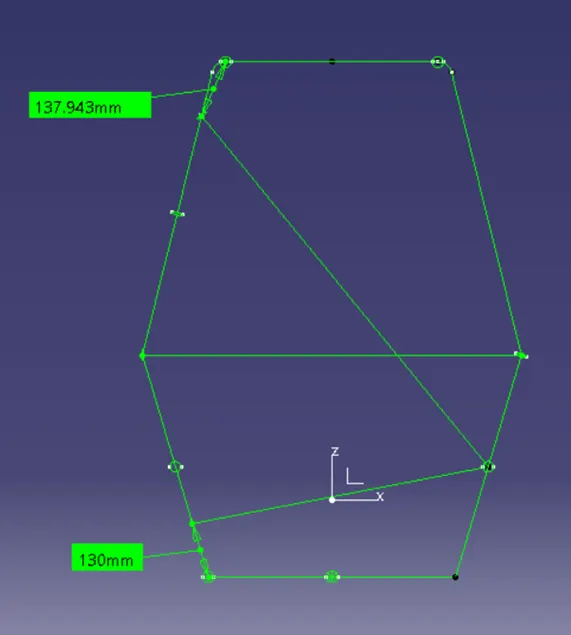
3.1.3. LDB – Lateral Diagonal Brazing
The Lateral Diagonal Brazing is done following the rules shown below.
3.1.4. RHO- Roll Hoop Overhead Members:
The Model for designing the Cage was provided by BAJA SAE rulebook. This model is designed as per the dimensions given.
4. Seat Design:
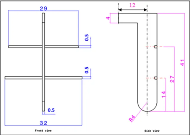
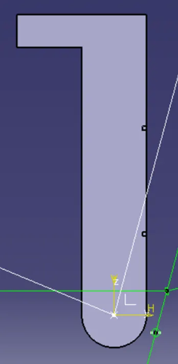
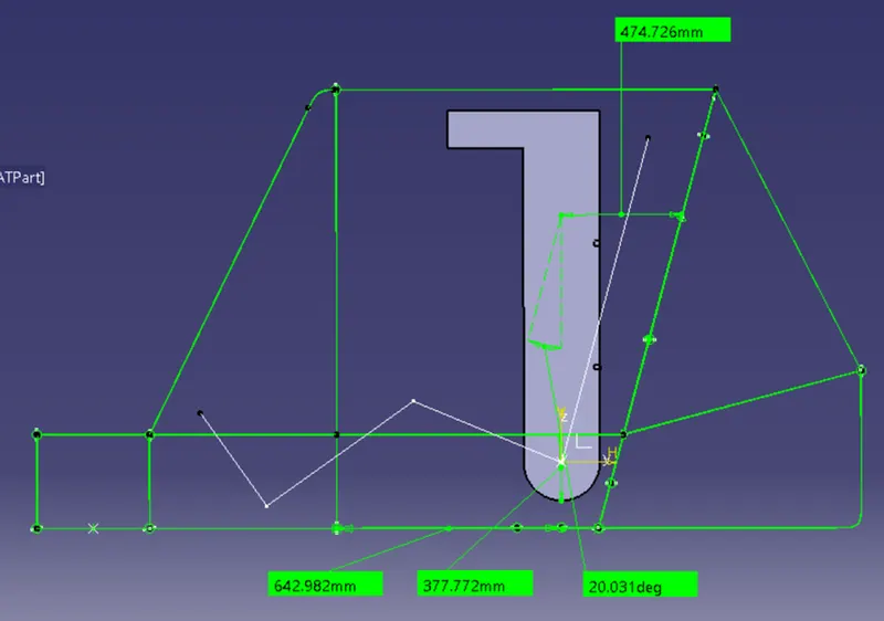
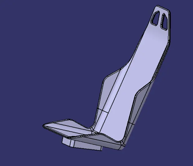
The seat is responsible for the comfort riding of the vehicle. The seat material is chosen as hard plastic or aluminium for lightweight and high strength. The seat belt is provided with the restrict the rider from moving around the cage.
The seat is designed to accommodate a rider with approximate dimensions a real human.
5. Front-wheel assembly:
The front wheel assembly consists of the following parts.
- A Forks
- Ball and socket joints
- Steering system
- Brake disc pad
- Brake callipers
- Front axle
- Wheel hub
- Bearings
- Wheel rim and Tire
- Suspension System
5.1 A forks design:
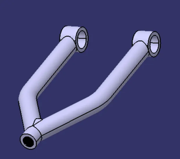
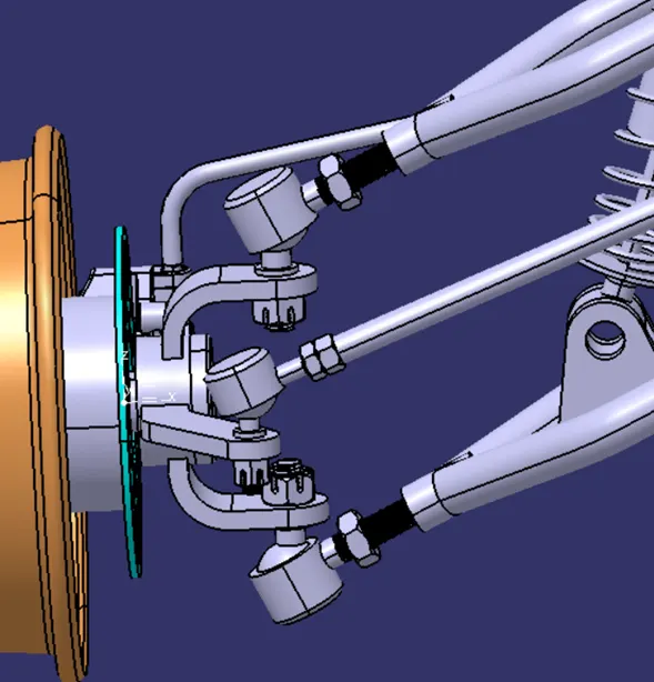
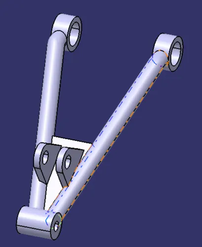
The A forks hold the entire front load of the structure. The front-wheel axle is lateral endpoint is fixed as per the design requirements. The rim and tire are then designed from this point. The A forks are made of steel tubes. The gussets are attached for holding the suspension system.
5.2 Ball and socket joints :
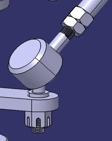
The front wheel has both vertical movement and steer mechanism attached to it. Hence a special type of joint is required for this function. The ball and socket joint is used for this purpose. The Ball and socket joint has more degrees of freedom that could accommodate our need.
5.3. Steering system :
5.3.1 Steering Column assembly:
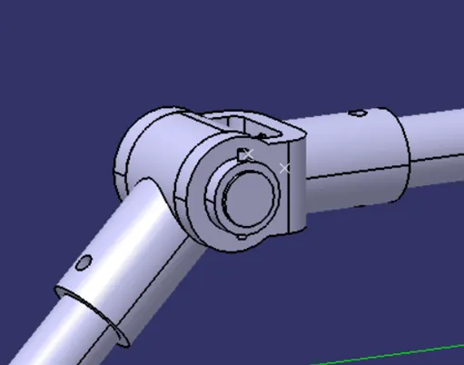
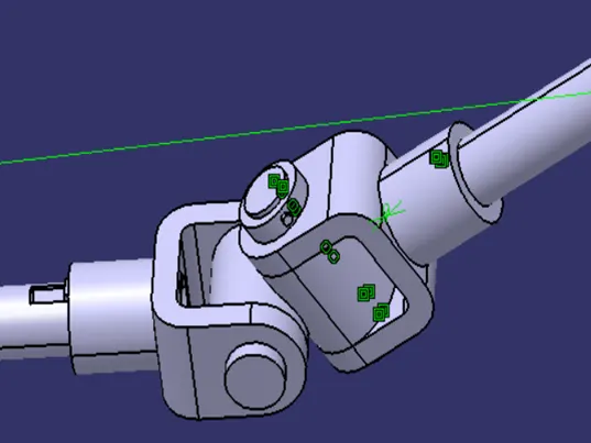
- The steering rods are connected by universal joints.
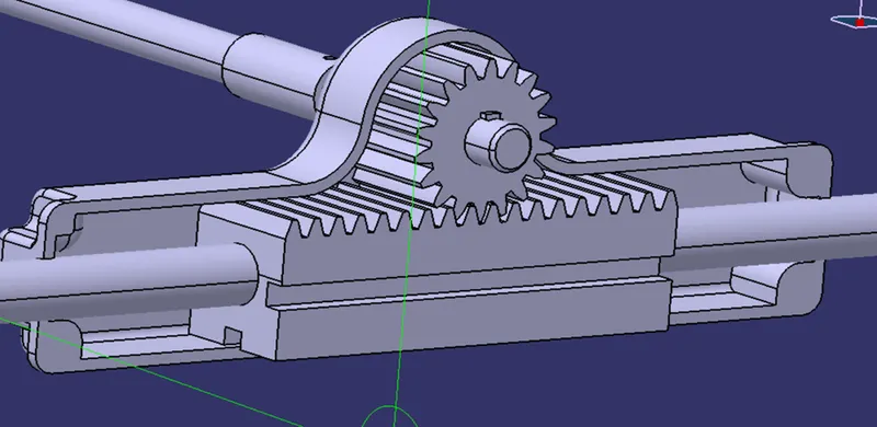
- The rack gear and the tie rod are connected using knuckle joints
- The tie rod and the wheel hub ball and socket joints
- The steering rods and the pinion gears are attached using splines.
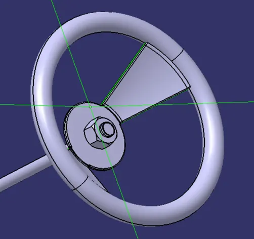
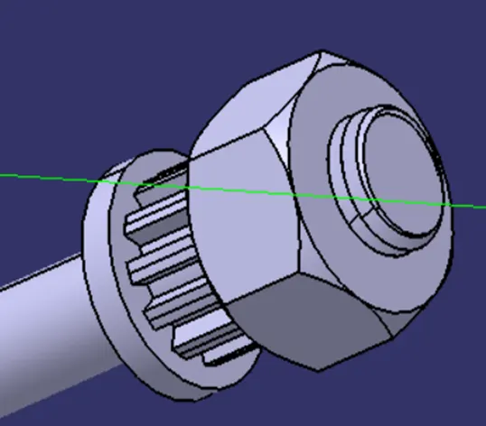
- The steering wheel can be removed easily by the nut given and the spline is provided for the best angular movement.
The steering system is responsible for the turn of the vehicle. The steering system has the components namely rack gear, pinion gear, splined shaft, steering wheel, ball and socket joint.
The design procedure and calculation are shown below,
- The steering column is required to control the direction of movement of the Cart.
- The steering Column is designed by following Ackermann steering mechanism.
- The system has a rack and pinion gear set up, tie rod, ball and socket joint, universal joints, steering wheel for the construction.
Ackerman Steering:
A vehicle with four wheels requires a special steering setup to drive efficiently. If a vehicle were to drive with what is known as parallel steering, at least one tire will scrub along the ground. This is because during a turn, the four tires are not turning about a common point. Instead, three tires are rolling along the ground, while one is slipping. To prevent this, the Ackermann steering setup was invented. Ackermann steering adjusts the steering of each front wheel such that the inside wheel (inside of the turn) is turned more than the outside wheel. For a vehicle with a given wheelbase (𝑙) and front track (𝑤), the outside wheel turn (𝛿o) for a given inside wheel turn (𝛿i), or vice versa, can be found using the following equation:
cot 𝛿o − cot 𝛿i = 𝑤/l *x
This equation is known as the Ackermann condition. If a given set of the four parameters satisfies the equation with 𝑥=1, that particular set qualifies as 100% Ackermann. However, no simple mechanical linkage configurations can follow the Ackermann condition perfectly throughout the steering motion, so Ackermann is usually stated as the value 𝑥 that satisfies the equation for a particular set of wheel turn angles.
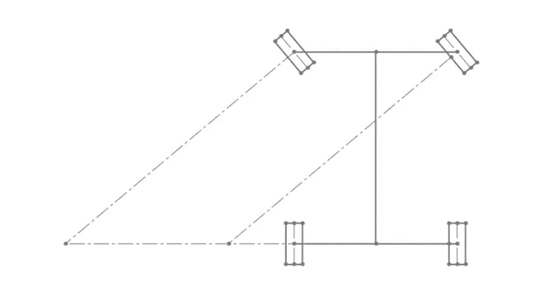
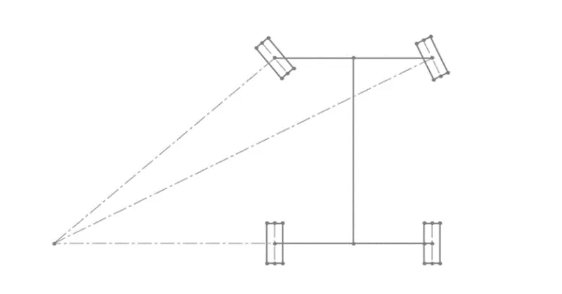
Traction is an important factor in order to manoeuver a vehicle Ackermann steering geometry provide pure rolling motion or prevent slipping of tires, which is appropriate for Baja where there is speed limit of 60 kmph. Whereas anti-Ackermann (reverse ackermann) geometry is used in high speed vehicles, which is appropriate for formula one cars.
Perfect Ackermann steering geometry states that the imaginary line from the steering pivot points inward so as to lie on a line drawn between the steering kingpins and the center of the rear axle. the inner wheel deflects more angle than outer wheel.
5.3.2 Steering Design Calculation:
Predefined parameters:
- Base Length = 60” (b)
- Track Width = 56” (a)
- Pivot to pivot = 43.7” (c)
Ackermann Angle = Tan-1(c/2b)
= Tan-1(43.7/(2*60))
= 20o
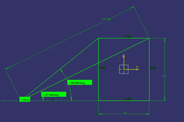
Assuming the turning Radius to be 4mm,
Outer turning angle = 25.986o = 26o
By Ackermann equation, cot α – cot β = c/b;
Solving the above equation we get β = 39o
Where α and β are the outer and inner turning angles.
Inner Turning Radius = 2800mm
5.3.3 Rack and Pinion Design:
Minimum number of tooth in pinion:
Zp = 2ha / (m*sin2φ)
= 2/(sin220o)
= 18
Where,
m = module,
ha = addendum,
hf = dedendum,
c = clearance,
Pinion Specifications,
m = 2mm,
addendum = 1*m = 2 mm,
dedendum = 1.25*m = 2.5mm,
clearance = 0.25*m = 0.5mm,
working depth = 2.25*m = 4.5 mm,
tooth thickness = 1.5708*m = 3.14 mm.
m= pcd/ Zp
therefore, pcd = m* Zp = 2 *18 = 36 mm.
where pcd = pitch circle diameter, Zp = number of teeth in pinion.
Steering Ratio:
Approximating maximum turn to be of 25 degrees and steering wheel movement to be 180 degrees the steering ratio can be calculated as,
S.R = 180/25
= 7.2
Rack Travel:
The steer wheel travel for one complete rotation = 2*pi*r
= 691.1 mm
S.R = Steer wheel Travel / Rack Travel.
7.2 = 691.1/rack travel
Rack travel = 95.98 mm = 96 mm.
No. of teeth in the rack:
mp = mr
36/18 = dr/tr
Rack travel = pi*dr
96 = pi*dr
dr = 30.55
= 31
Therefore the number of teeth in rack = 16
5.4. Brake disc pad :
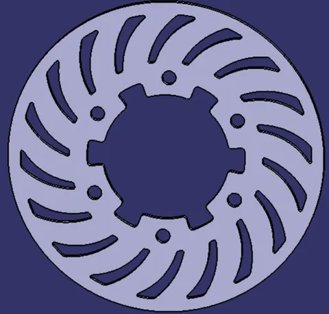
Disc brake is chosen for braking the ATV. The brake dimensions are 180 mm diameter.
5.5. Brake caliper :
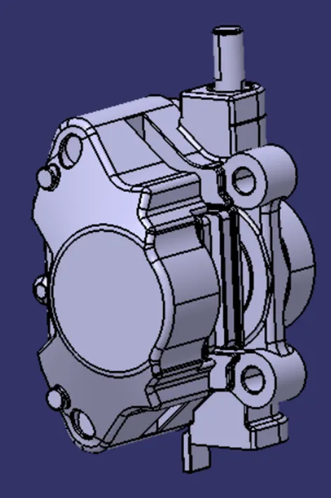
Vespa brake caliper is used for the disc brake. This is a floating type brake caliper.
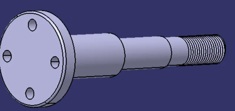
5.6. Front axle :
The front axle is designed as per the load calculations. The axle has threaded end to get assembled with the wheel hub. The following images show the axle dimensions and design.
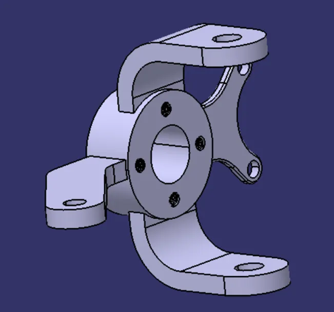
5.7. Wheel hub Design :
The hub is responsible for all the assembled parts in the front wheel assembly. The hub is assembled with ball and socket joints for the forks and steering assembly, disc brake, brake calipers, bearings and lock nut.
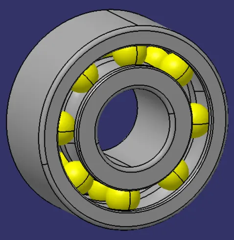
5.8. Bearings :
SKF manufactured deep grove ball bearings are chosen for our structure design. The deep groove ball bearing can bear heavy radial and axial load at the same time.
5.9. Wheel rim and Tire :
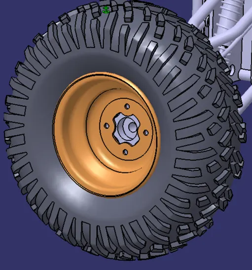
There are different types of tyre available in the market for the ATV. The types included mud tyre, racing tyre, snow tyres, etc. The Carlisle AT489 23x7-10 tyre is chosen for our ATV. The Tire dimension are 23 inch diameter and 7 inch width. The rim for the wheel is designed by considering the tire dimensions.
5.10. Suspension System :
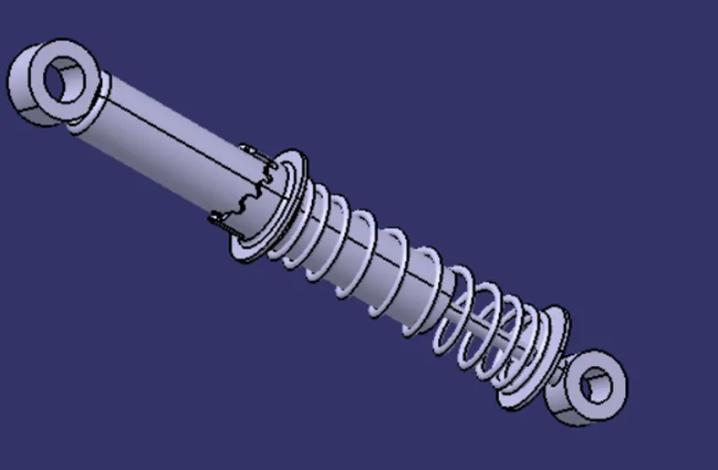
The suspension system is responsible for smooth riding of the vehicle. The suspension system is required for damping the vibration created while riding the vehicle. The Tension in the spring coil equals the impact forces created in the ATV. The impact energy created in the atv is absorbed by the spring while in operation.
6. Rear-wheel assembly:
The rear wheel assembly consists of following parts
- A forks
- CV joint
- Rear Hub
- Rear-wheel and rim
- Suspension system
- Locknut
- Brake disc
- Brake calliper
- Brake fluid cables
6.1 A forks :
The A forks hold the entire front load of the structure. The front-wheel axle is lateral endpoint is fixed as per the design requirements. The rim and tire are then designed from this point. The A forks are made of steel tubes. The gussets are attached for holding the suspension system.
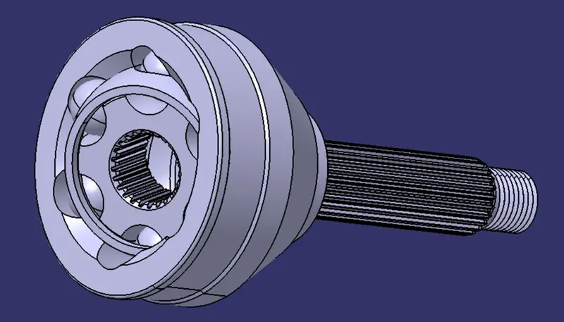
6.2 CV joint :
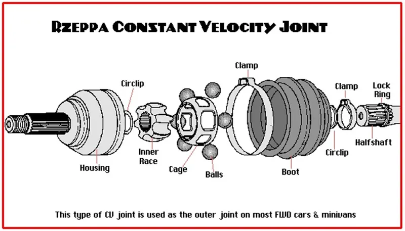
The constant velocity joint is a type of joint used for transmitting power in variable angles. This joint is required to compensate the movement of the wheel with respect to the ATV cage.
Different types of CV joint:
- Rzeppa joint
- Tripod Joint
- Double carden joint
6.2.1 Rzeppa CV joint:
Rzeppa joint consists of six balls, six grooves,
outer shells, housing, cage, boot, etc. This joint is chosen for our need in the design of ATV.
6.3 Rear hub:
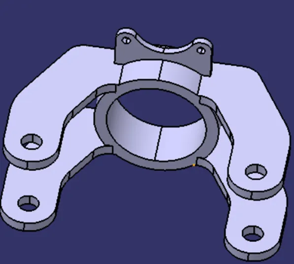
The hub hold the parts namely, brake disc, bearing, brake calipers, brake fluid cables and others parts.
All other rear wheel parts mentioned above are same as the front wheel assembly.
7. Gear box design and positioning :
7.1 Gear Box design:
Given specifications:
Max speed of vehicle in road = 60 kmph = 16 m/s
RPM of engine (max) = 3800 rpm
Idle speed = 1750+/- 100 rpm
Power of engine = 10 hp = 7.46 kw
Torque of engine = 19.67 Nm
CVT (Continuously Variable Transmission) ratio = 0.4 to 3.1
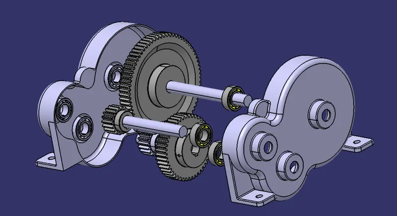
Gearbox gear ratio is determined as 10:1
Since gear ratio big we are going with a two-stage gearbox with the reduction of speeds in steps of 2.5:1 and 4:1.
For ready availability of gears we go for standard available gears
|
Stage |
SI. No |
No. of teeth |
Module |
PCD |
|
I |
1 |
18 |
3 |
54 |
|
I |
2 |
45 |
3 |
135 |
|
II |
3 |
18 |
3 |
54 |
|
II |
4 |
72 |
3 |
216 |
7.3 Gearbox and engine Mounting:
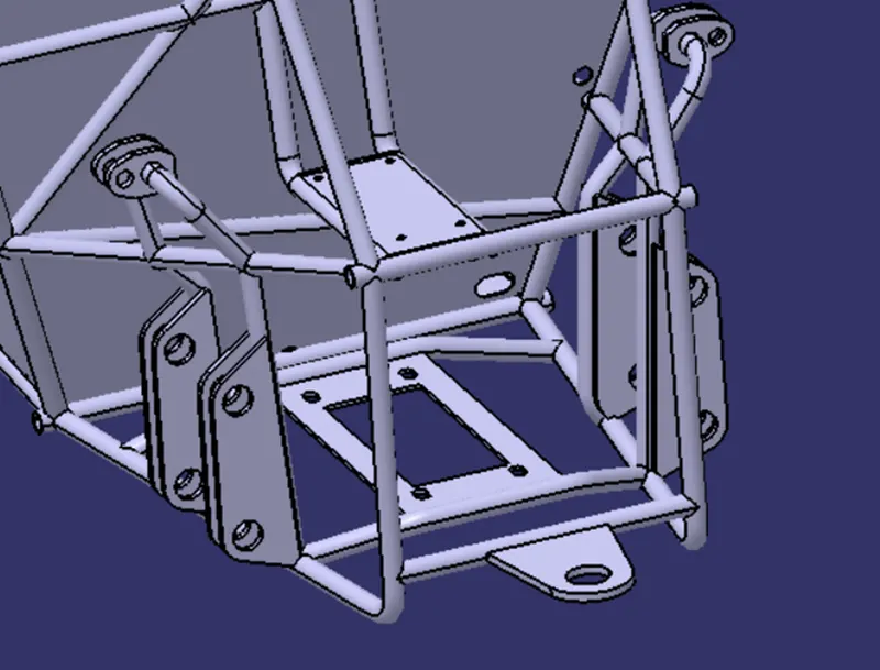
The mounting plates are designed for easy removal of engine and gear box for the service purpose.
7.4 Continuous variable Transmission:
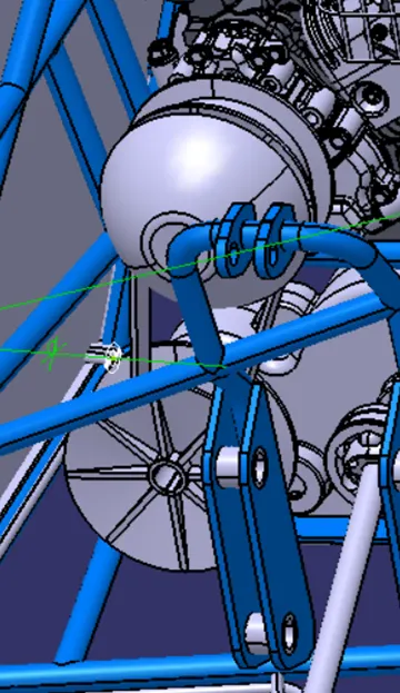
The CVT is used for the transmission of the power from the prime mover to the gear Box. The Cvt is responsible for the change in torque requirement as the condition of the vehicle.
8. Brake and acceleration Pedal Assembly:
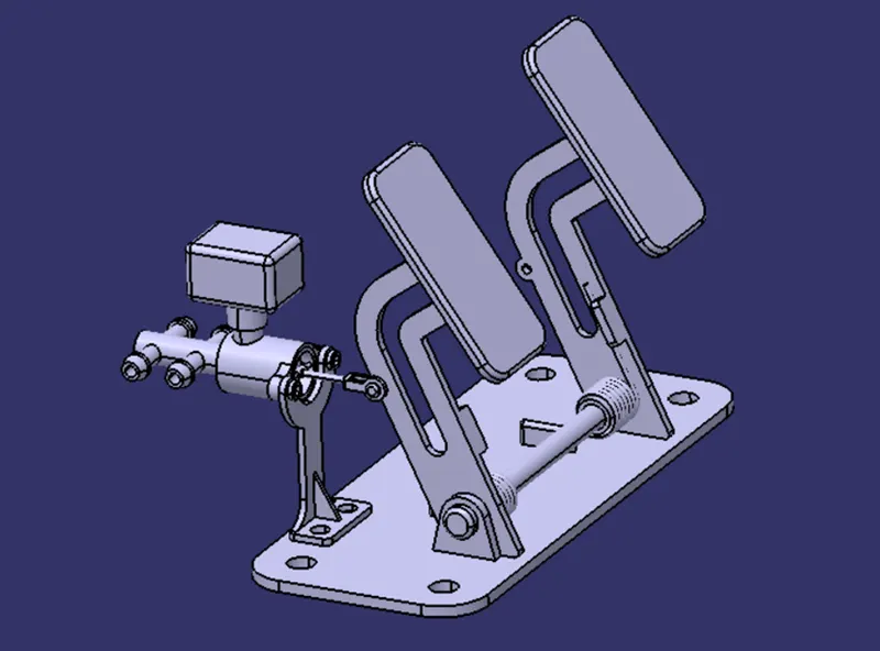
- The brake and acceleration pedals are designed as the comfort and requirement of the driver.
- The brake pedal is attached to the master cylinder for the supply of hydraulic fluid to the disc brake for braking needs.
- The tubes for the oils supply is also designed.
9. Fuel Tank:
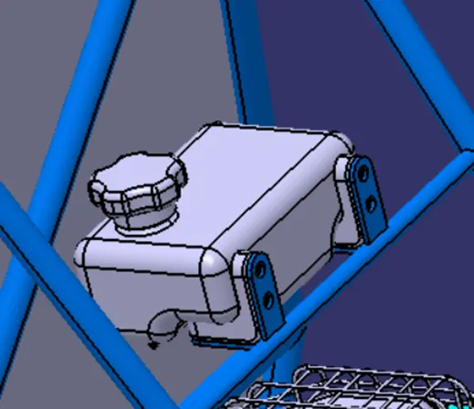
The fuel tank is required for the continuous supply of the fuel for the engine.
The fuel tank is attached at the topside of the cage for easy refilling of the fuel
10. Cables:
11. Renderings:
12. Conclusion:
The ATV is designed as per the rulebook specified by BAJA SAE India and the simulations are also made for the design.
13. Renderings:
13. References:
- https://www.bajasaeindia.org/pdf/BAJASAEINDIA_2020_RULEBOOK_REV002.pdf
- https://grabcad.com/library?page=1&time=all_time&sort=recent&query=baja
- https://www.youtube.com/watch?v=6ledGT8O9NM
- https://www.youtube.com/watch?v=wuR9hd54qwE
- https://www.youtube.com/watch?v=gHBb8FHlXBg
- https://www.youtube.com/results?search_query=dmu+kinematics+to+animation
- https://www.ijert.org/research/design-methodology-and-manufacturing-of-rack-and-pinion-for-all-terrain-vehicle-IJERTV8IS060334.pdf
- com
- https://www.ijert.org/design-and-analysis-of-gearbox-for-sae-baja-competition
- https://www.ijert.org/research/design-and-analysis-of-gearbox-for-sae-baja-competition-IJERTV9IS050719.pdf
- https://www.google.com/url?sa=i&url=https%3A%2F%2Fwww.aa1car.com%2Flibrary%2Fcvgrind.htm&psig=AOvVaw0QyIElRs7M-hinlSbo0yNJ&ust=1647850348191000&source=images&cd=vfe&ved=0CAsQjRxqFwoTCNiXuIqf1PYCFQAAAAAdAAAAABAD
- https://www.discounttiredirect.com/learn/atv-tire-types