FLOW OVER A BACKWARD FACING STEP USING CONVERGE CFD
Aim: To simulate the flow of air through a backward facing step using Converge CFD
1. Setup and run the simulation for three different grid sizes and compare the results obtained.
2. Plot the Velocity and Pressure contours for the three mesh sizes.
3. Study where and why flow separation is taking place.
Problem Definition:
The geometric specification for the backward-facing mesh is as shown;
The working fluid is air. It is flowing into the backward-facing step from the left at an inlet total pressure of 110325 Pa and exiting from the outlet at a static pressure of 101325 Pa.
Introduction and Theory:
The study of airflow over buildings and other man-made structures has gained importance and a lot of research has happened in the past few years due to the possibility of operation of short take-off and landing (STOL) aircrafts within a city. Unsteady and turbulent wind flows pose a danger to these aircrafts.
In structural design like buildings and bridges it is very important to estimate the dynamic load imposed by these complex phenomena. There have been reports of severely unpleasant situations behind buildings and bridges due to strong recirculating flows. In this study the problem of flow separation behind an obstruction, its reattachment to the ground, and the recirculating flow in the cavity or the wake zone thus formed has been investigated and solved by considering the simple configuration of a backward-facing step. A lot of experimental data is available on this problem, this experimental data can be used to compare the accuracy of numerical solution obtained using a CFD tool or a computer code.
Flow Separation
Flow separation is the point at which the velocity gradient at the surface in a direction normal to the wall decreases to zero. Flow separation happens due to presence of either viscosity or pressure gradient or due to abrupt change in geometry. Flow separation due to abrupt change of geometry in most structures happens due to sharp edges. Separated flows are formed up-srteam of a forward facing step, downstream of a backward facing step, within a cutout in a body surface, and on the upper edge of airfoil at high angle of attack.
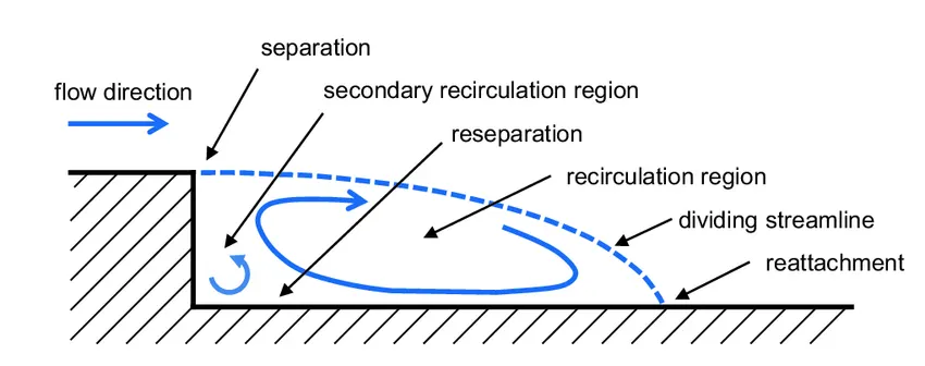
Image Courtesy: www.researchgate.com
In the case of a backward facing step the flow gets separated at the step due to change in geometry. The above image shows the recirculation zone which happens due to flow separation. In this zone eddies form i.e. air flows in a circular fashion. Then after the recirculation zone there is reattachment i.e. flow again happens over the surface.
Case Setup:
1. Load the geometry and assign the boundaries.
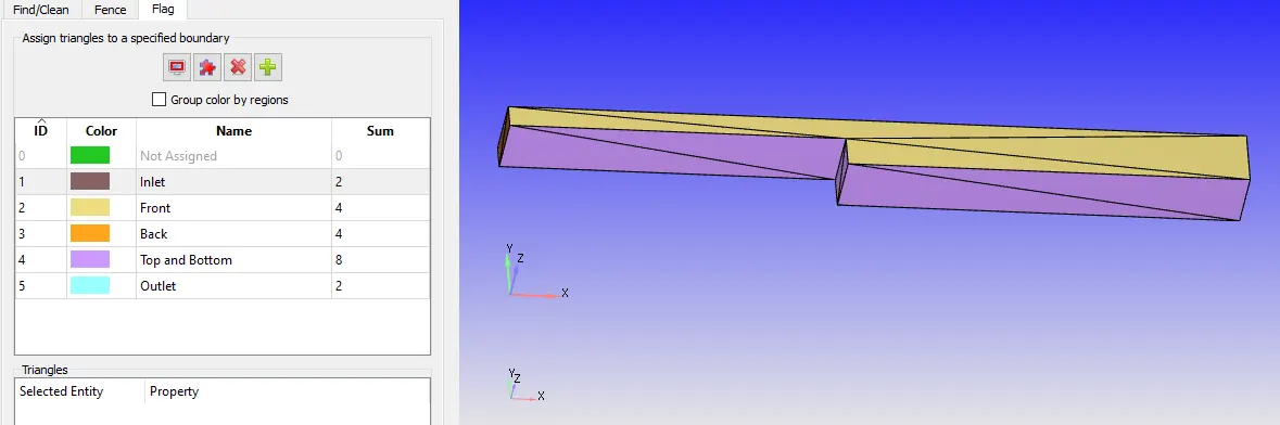
Create 5 boundaries for Inlet, Outlet, Front, Back, one for Top and bottom as shown in the above image.
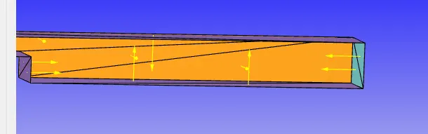
2. Check the direction of Normals. The direction should be inside the fluid region if not change the direction of normals as show below.
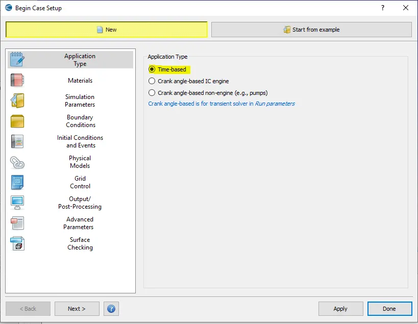
3. Begin Case Setup.
3.1 select time based
3.2 For materials select air and press done
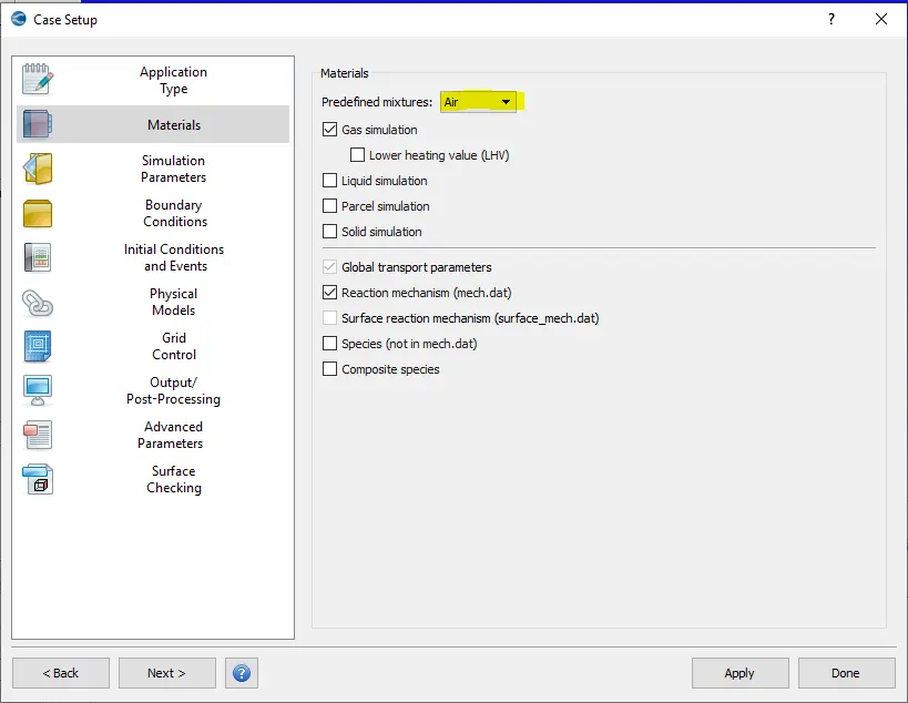
3.3 Select OK for Global Transport properties

3.4 Run Parameters
Under Solver tab change the solver to Steady state solver.
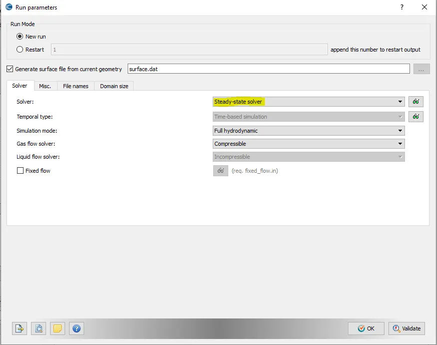
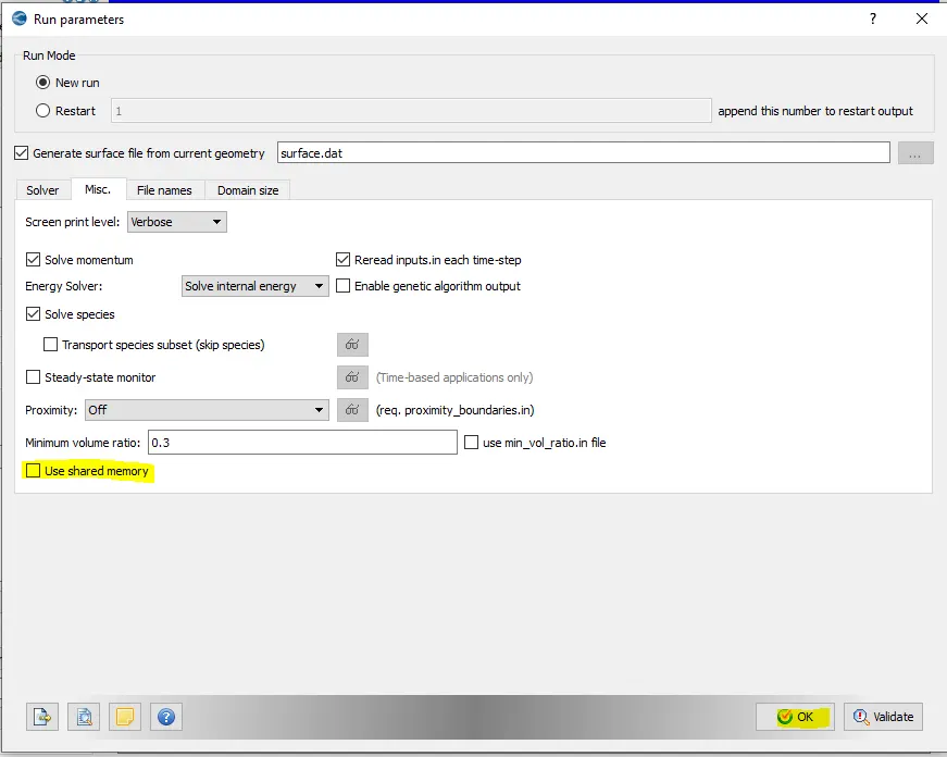
Under Misc. tab uncheck the checkbox "Use Shared Memory" and press OK.
3.5 Simulation Time Parameters
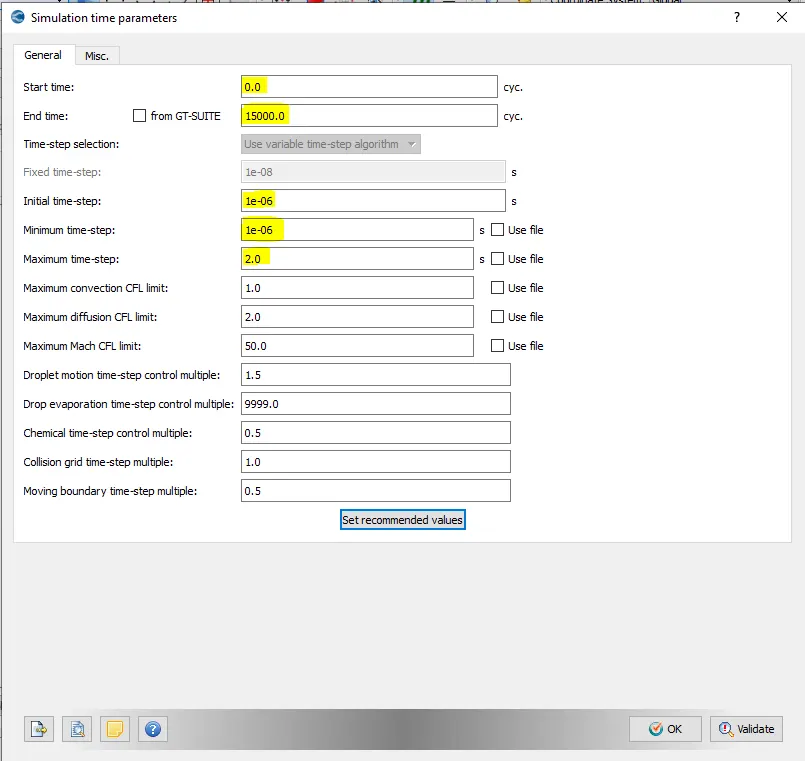
Set the start time as 0, end time as 15000 cycles, Initial and minimum time step as 1e-6 and Maximum time step as 2 seconds.
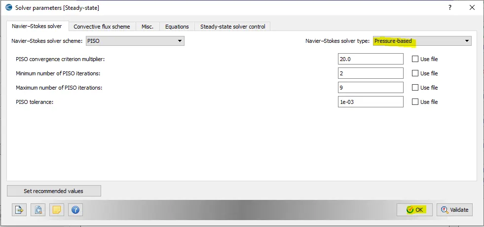
3.6 Solver Parameters
Change the Navier stokes solver type to Pressure Based and keep all the other settings as default and press OK.
3.7 Regions and Initializations
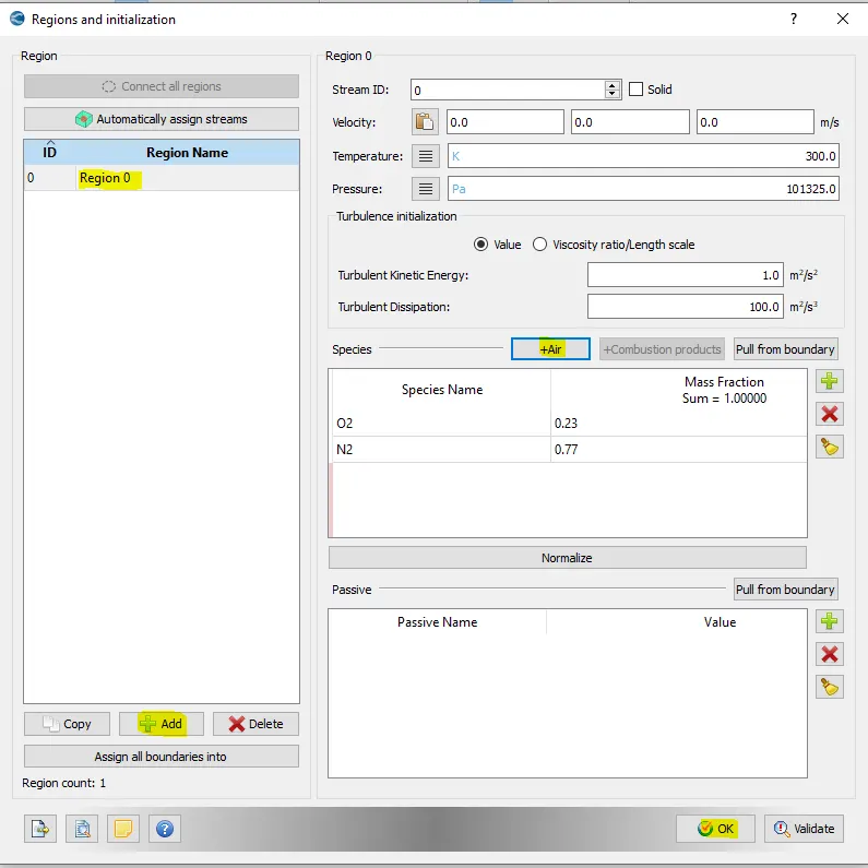
This defines a volumetric region with initial conditions like initial pressure, initial temperature, velocity and species concentration.
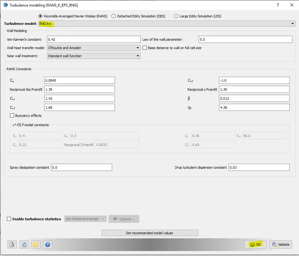
3.8 Turbulence Modelling
Keep the Turbulence model as RNG k-epsilon and press OK.
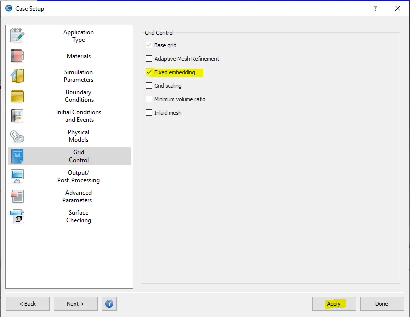
3.9 Grid Control
Enable Fixed embedding check box and press OK.
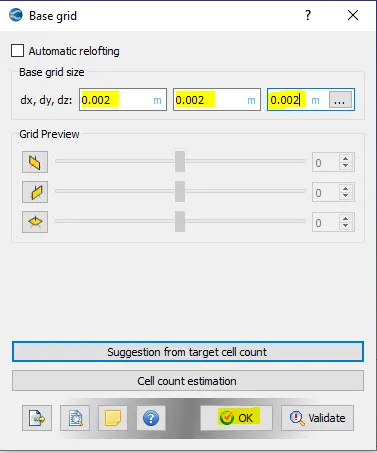
3.10 Base Grid
Set the mesh size to 2e-3.
3.11 Fixed Embedding
We want finer mesh around the top and bottom walls and we can achieve that using Fixed Embedding.
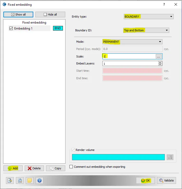
Select Add, set the entity type as boundary, mode as Permanent and scale as 1 then press OK.
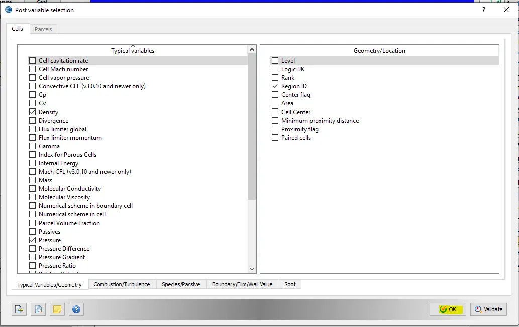
3.12 Post Variable selection
Keep all the default settings and press OK
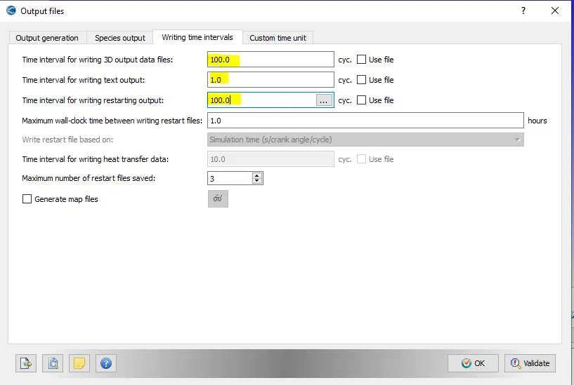
3.13 Output Files
Change the values as shown below and press OK.
3.14 Boundary
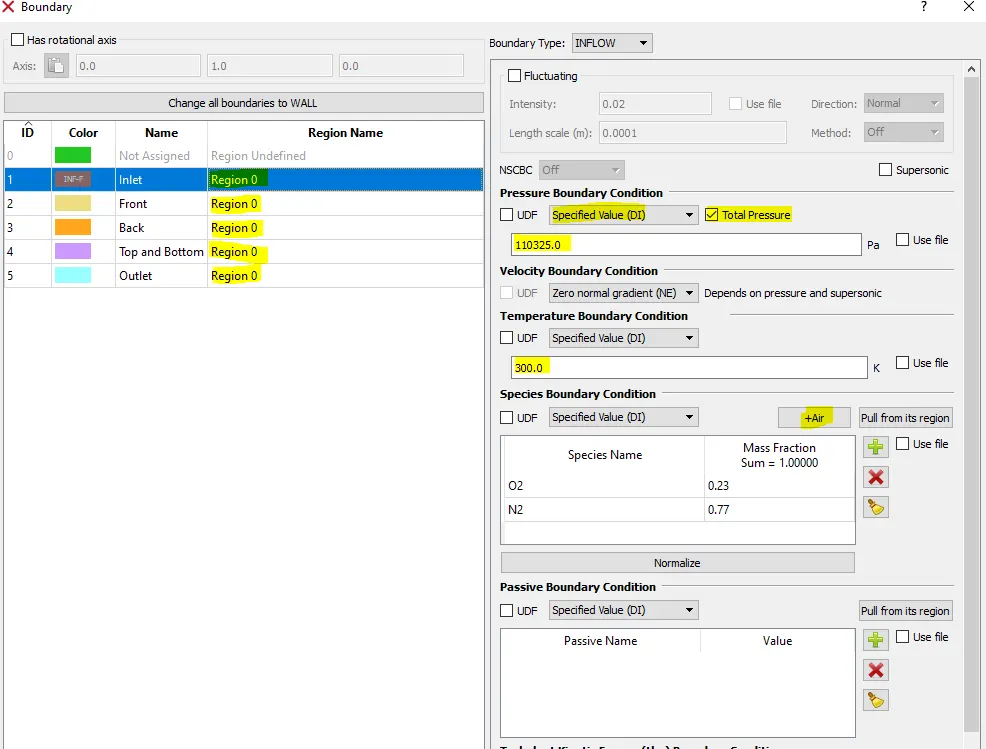
For Inlet set the pressure boundary condition as Specified Value of 110325 Pa (10,000 Pa above atmospheric pressure), keep the temperature boundary condition as it is (Specified value of 300K) and finally select the species boundary condition as air. Select the Region Name as Region 0 for all the boundaries as defined in the Regions and Initialization.
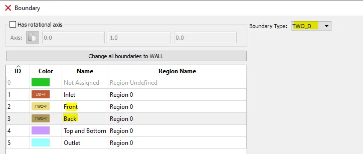
For Front and Back boundaries select the boundary type as TWO_D as there is no flow happening in that direction and we only want a 2-dimensional simulation.
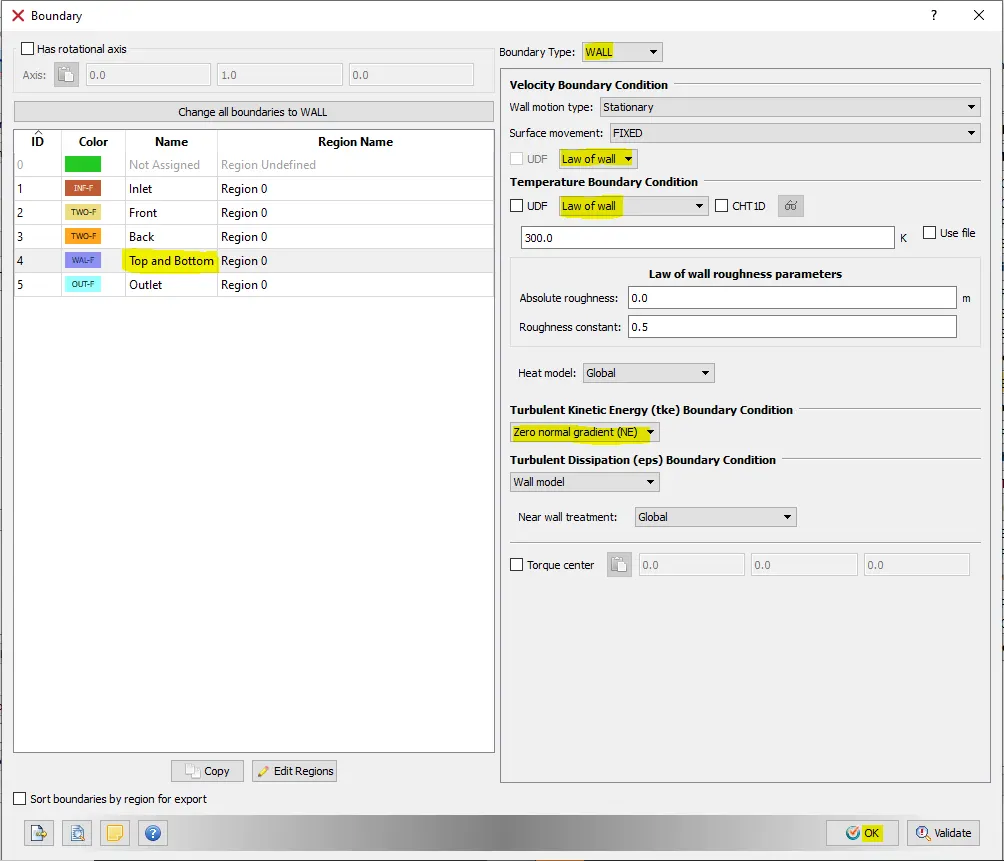
For Top and Bottom walls select the Boundary Type as WALL and for velocity and Temperature boundary conditions select Law of wall.
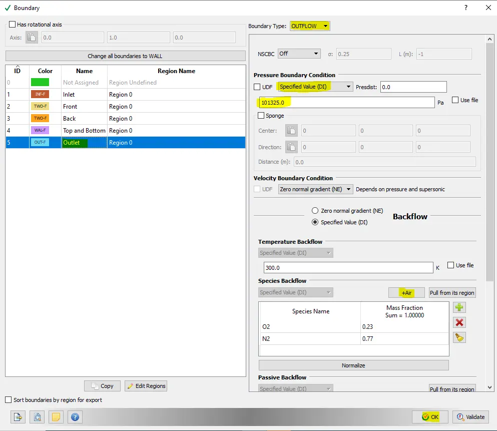
For outlet, select the pressure boundary condition as specified value of 101325 Pa and for species backflow select air as the species.
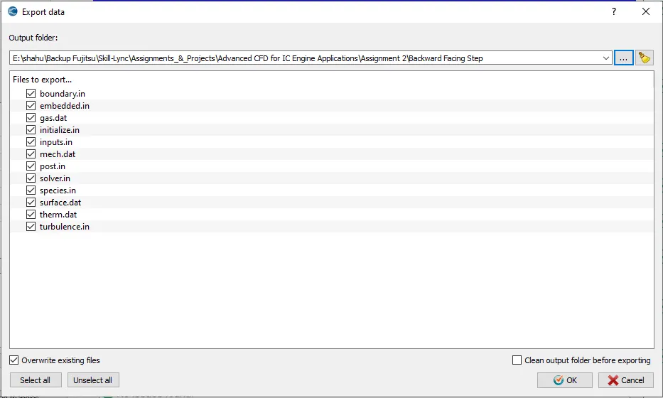
4 Export all the input files.
5. Copy and paste the mpiexec.exe file to the folder in which the input files are exported.
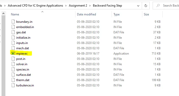
The executable file mpiexec.exe is found in C:Program FilesConvergent_ScienceCONVERGE3.0.12binmpiintel64bin folder
Then copy the path to clipboard from the folder "C:Program FilesConvergent_ScienceCONVERGE3.0.12binconverge-intelmpi.exe".
6. To run the simulation, open cygwin and navigate to the folder in which the input files are exported and run the following command.
mpiexec.exe -n 4 "C:Program FilesConvergent_ScienceCONVERGE3.0.12binconverge-intelmpi.exe" restricted </dev/null> logfile1.txt &
Run the simulation for three different mesh sizes. (viz. 2e-4, 1.5e-4 and 1.2e-4 metres).
7. Post convert all the output files.
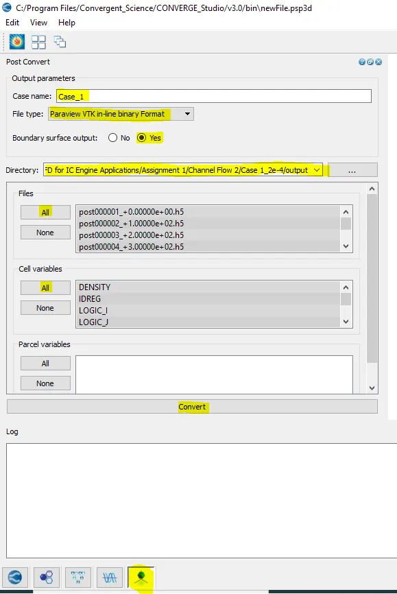
In the bottom left select the last icon to post convert the output files.
Enter the case name, select the file type as Paraview VTK In-line binary format, select boundary surface output to yes, navigate to the directory where the output files are located.
Then for files select all, for cell variables select all and hit Convert. Converge will take some time to post convert all the files.
Results of the Simulation:
Case 1: Mesh Size of 2e-3
Mesh (2e-3)

We can see that we have enabled Fixed Embedding and because of that the mesh size is finer near the top and bottom walls than the mesh in the core region.
Pressure Contour
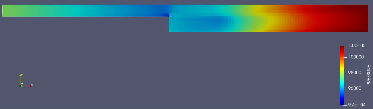
We can see that pressure drops near the step especially near the flow separation region.
Velocity Contour
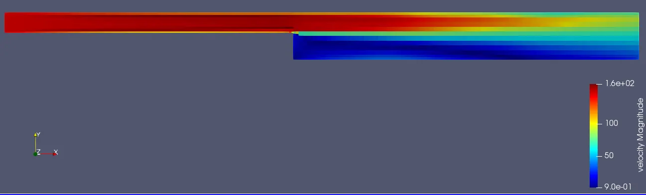

Observation:
1. We can observe that the velocity is high where the cross sectional area (Normal to flow direction) is low and vise versa.
2. Velocity is very low (close to 0.9 m/s) in the recirculation region
3. Flow of air is in a circular fashion (also known as eddies) in the recirculation region.
Pressure Plot
Static Pressure plot along the length of flow
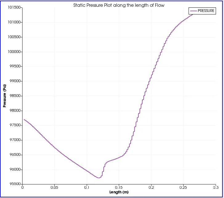
From the above plot we can observe that Static pressure drops near the backward step and then it again increases.
Pressure convergence plot
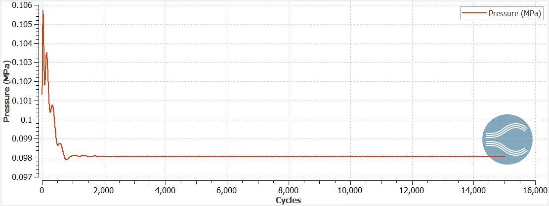
Observation from the plot:
Pressure converges after about 1500 cycles for the mesh size.
Velocity Plot
Velocity plot along the length of flow
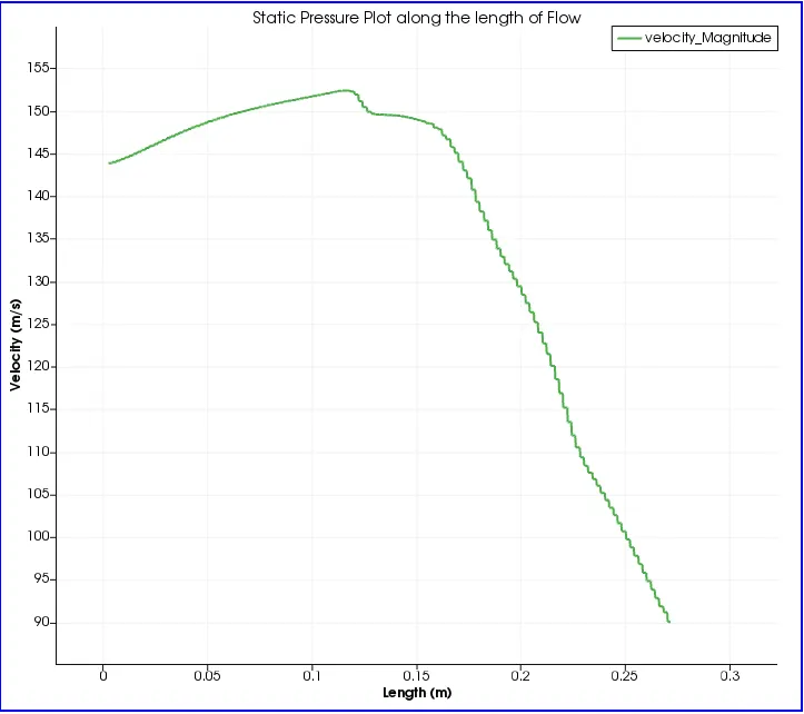
Observation:
1. Maximum velocity occurs near the backward facing step.
2. Maximum velocity is around 153 m/s
Average Velocity Convergence Plot
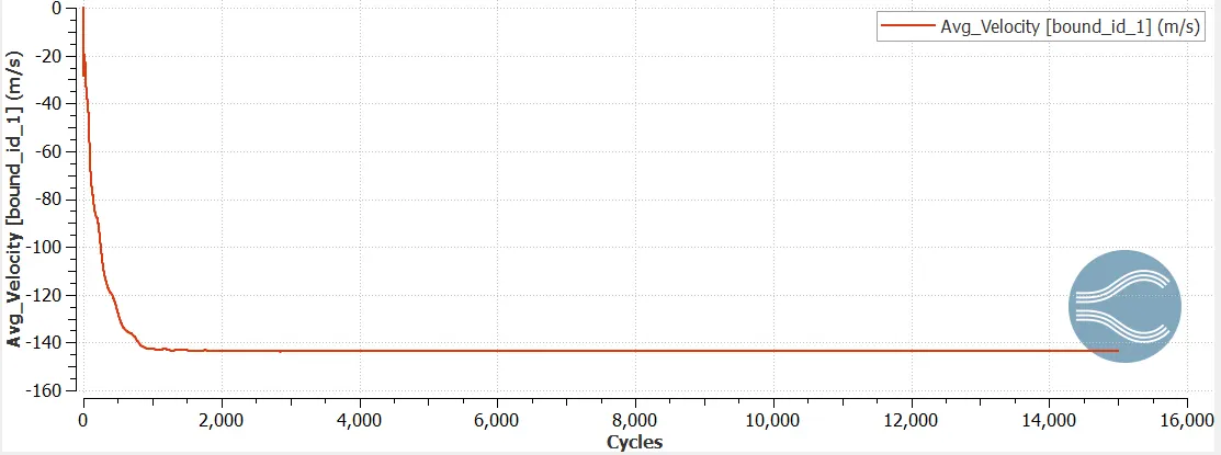
Average Velocity at inlet = 143.5 m/s
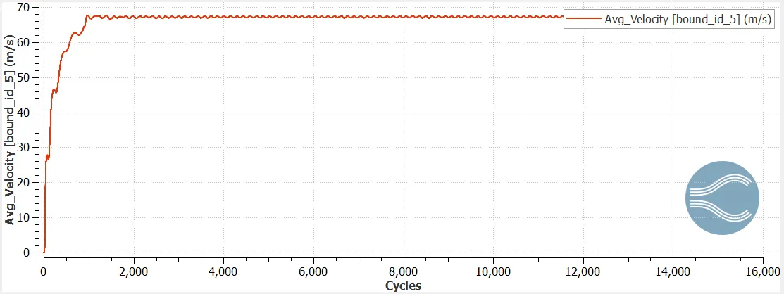
Average Velocity at Outlet = 67 m/s
Observation: Velocity converges after about 2000 cycles
Mass Flow Rate
Inlet
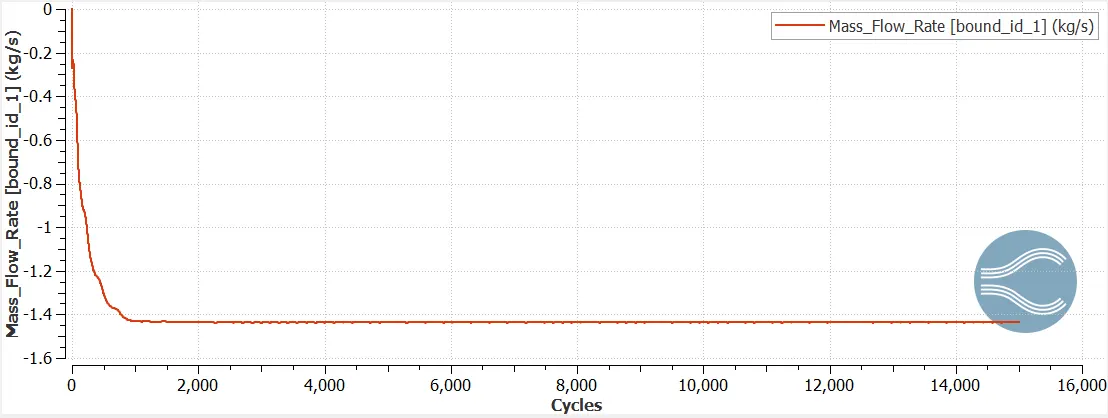
Inlet Mass Flow Rate = 1.435 Kg/s
Outlet
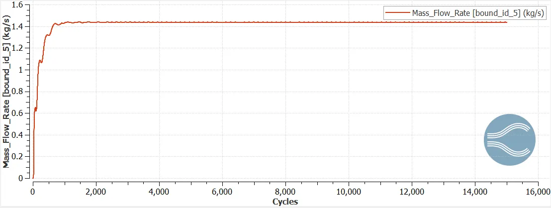
Outlet Mass Flow Rate = 1.435 Kg/s
Observation:
Inlet mass flow rate is equal to outlet mass flow rate, hence mass conservation is achieved.
Total Cell count
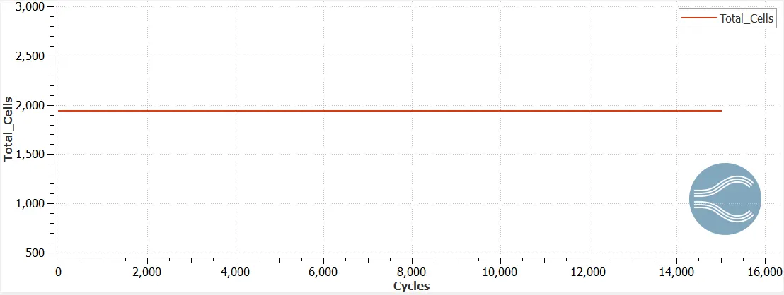
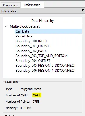
Total of 1943 cells
Case 2: Mesh Size of 1.5e-3
Mesh (1.5e-3)

We can see that we have enabled Fixed Embedding and because of that the mesh size is finer near the top and bottom walls than the mesh in the core region.
Pressure Contour
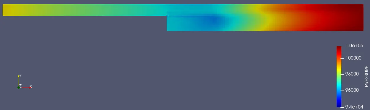
We can see that pressure drops near the step especially near the flow separation region.
Velocity Contour
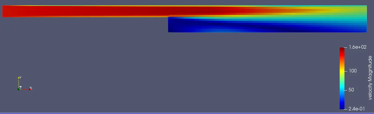

Observation:
1. We can observe that the velocity is high where the cross sectional area (Normal to flow direction) is low and vise versa.
2. Velocity is very low (close to 0.24 m/s) in the recirculation region
3. Flow of air is in a circular fashion (also known as eddies) in the recirculation region.
Pressure Convergence Plot
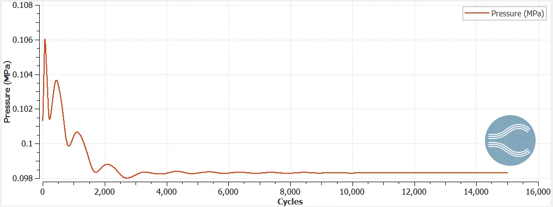
Observation from the plot:
Pressure converges after about 5000 cycles for the mesh size.
Average Velocity Convergence Plot
Inlet
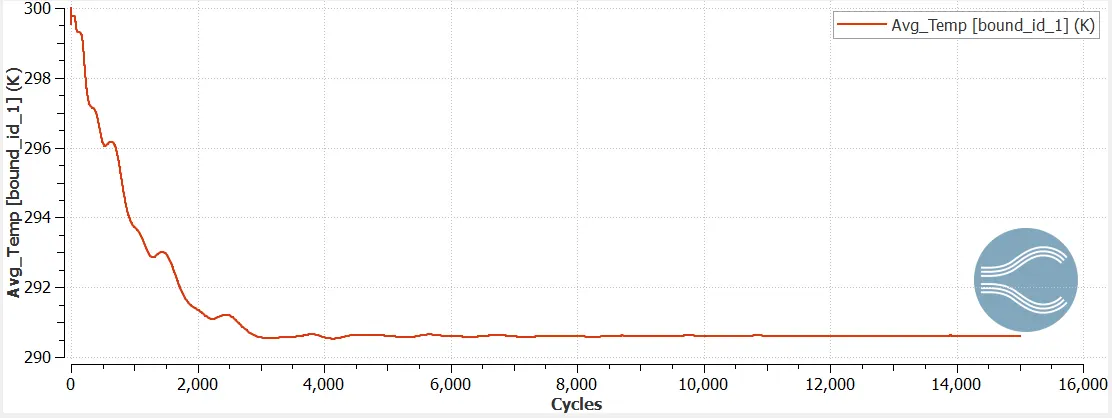
Average Inlet velocity = 290.6 m/s
Outlet
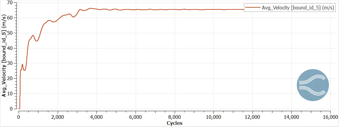
Average outlet velocity = 65.4 m/s
Observation: Velocity converges after about 5000 cycles
Mass Flow Rate
Inlet
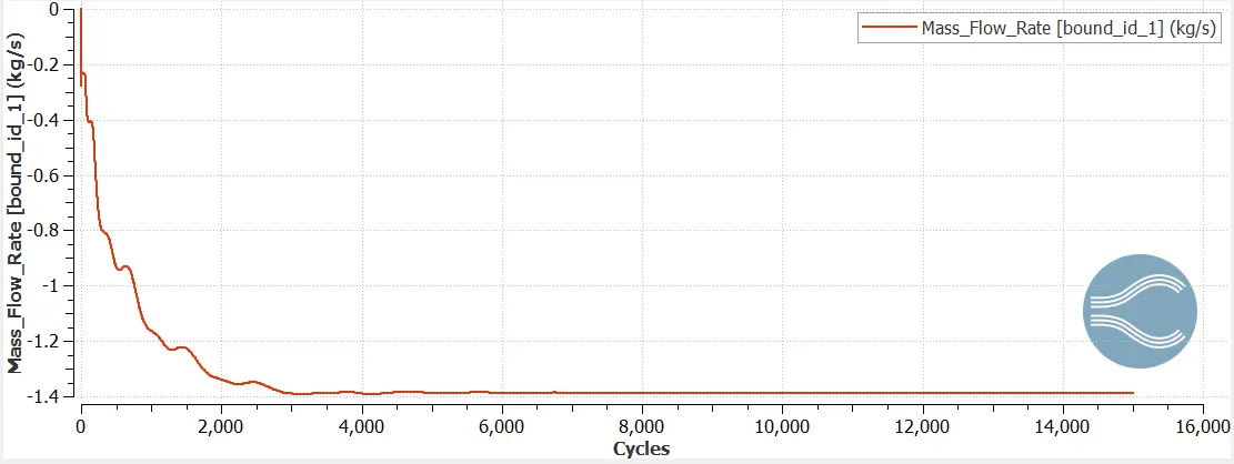
Average Inlet mass flow rate = - 1.387 kg/s
Outlet
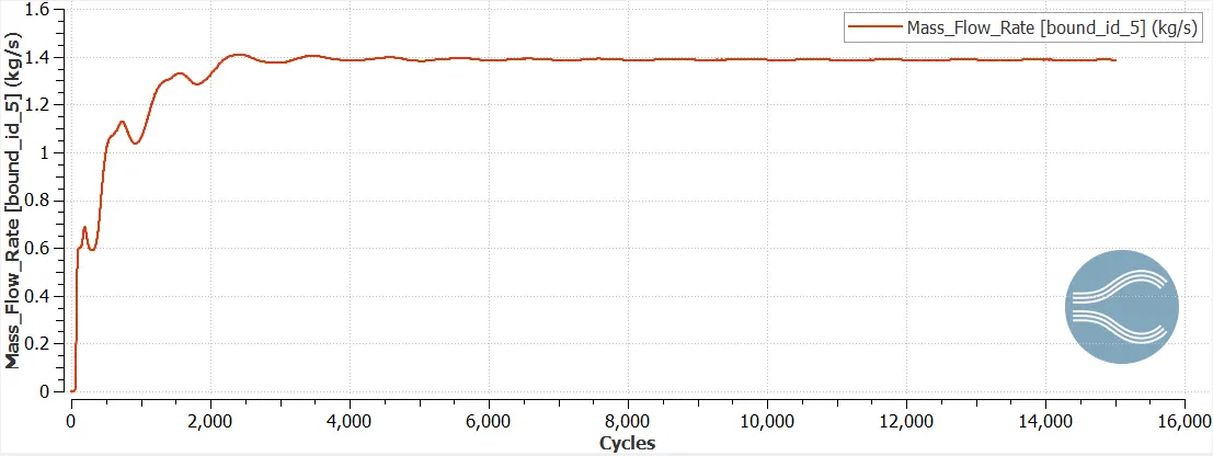
Average Outlet mass flow rate = 1.387 kg/s
Inlet mass flow rate = Outlet mass flow rate
Hence mass conservation is achieved
Total Cell count
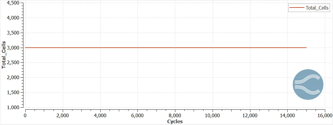
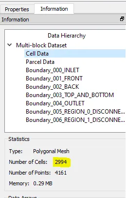
Total number of cells = 2994
Case 3: Mesh Size of 1e-3
Mesh

We can see that we have enabled Fixed Embedding and because of that the mesh size is finer near the top and bottom walls than the mesh in the core region.
Pressure Contour
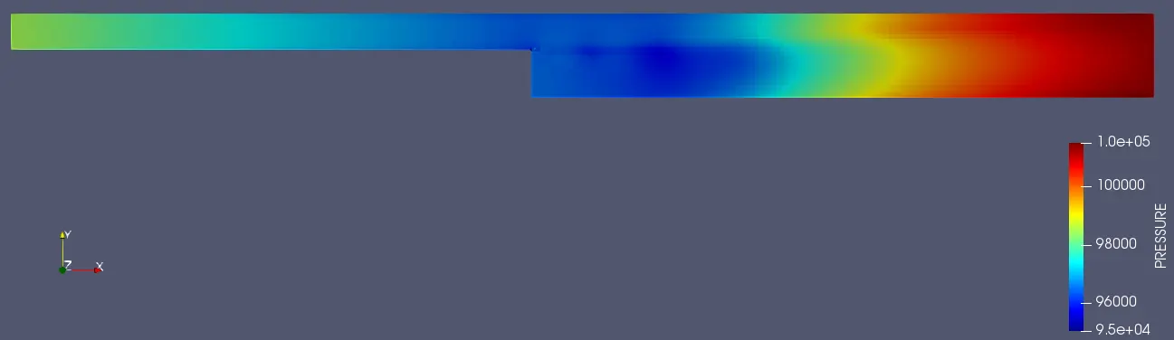
We can see that pressure drops near the step especially near the flow separation region.
Velocity Contour
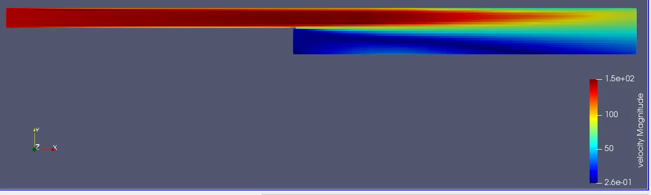

Observation:
1. We can observe that the velocity is high where the cross sectional area (Normal to flow direction) is low and vise versa.
2. Velocity is very low (close to 0.26 m/s) in the recirculation region
3. Flow of air is in a circular fashion (also known as eddies) in the recirculation region.
Pressure convergence plot in Converge
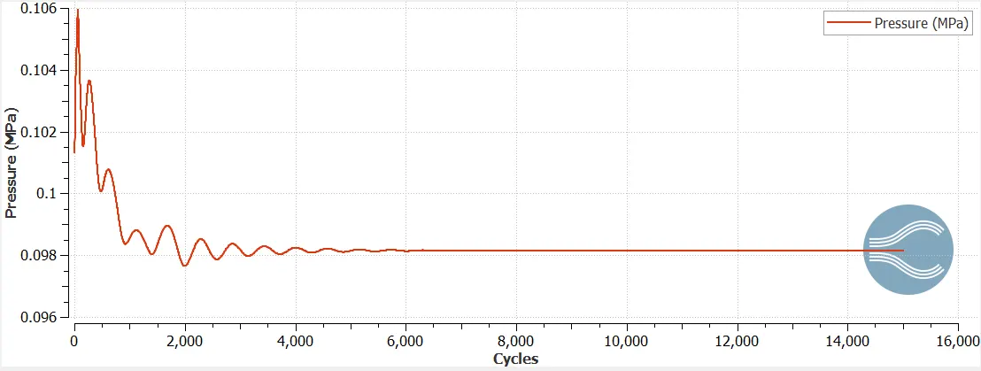
Observation from the plot:
Pressure converges after about 6000 cycles for the mesh size.
Average Velocity Convergence Plot in Converge
Inlet
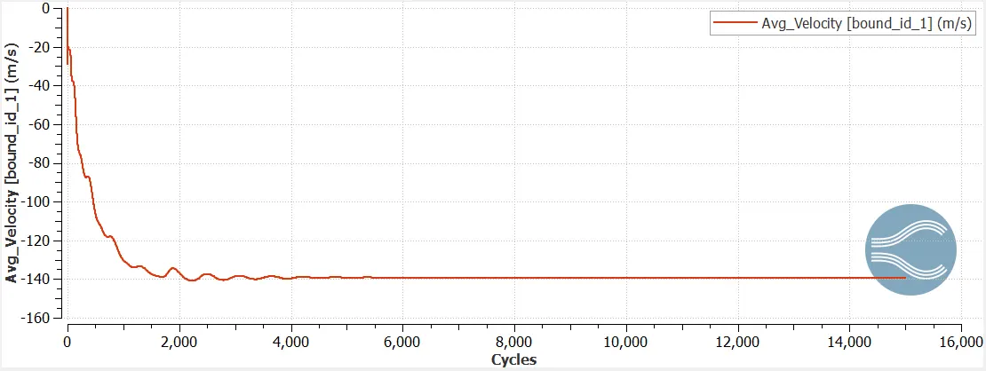
Average Inlet velocity = 139.27 m/s
Outlet
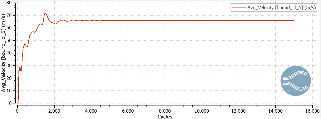
Average Outlet Velocity = 65.76 m/s
Observation: Velocity converges after about 6000 cycles
Mass Flow Rate
Inlet
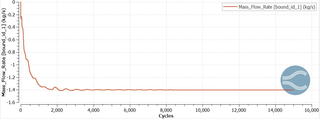
Inlet mass flow rate = 1.400 kg/s
Outlet
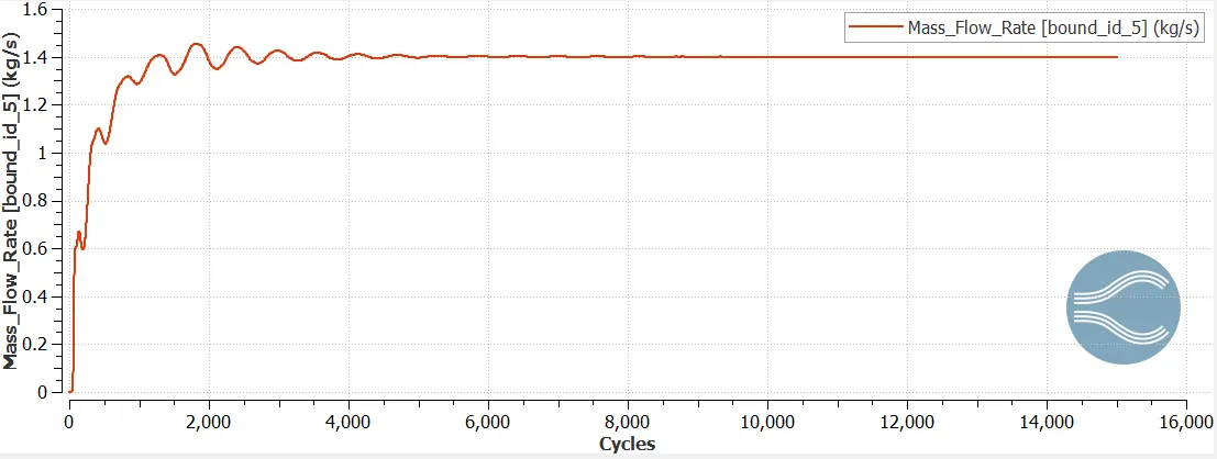
Outlet mass flow rate = 1.400 kg/s
Observation:
Inlet mass flow rate is equal to outlet mass flow rate, hence mass conservation is achieved.
Total Cell Count
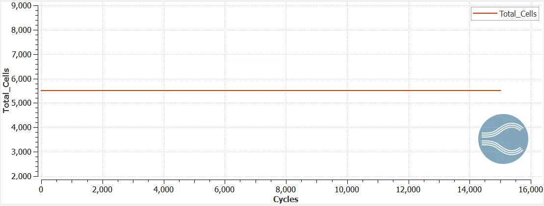
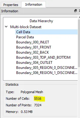
Total number of cells = 5516
Where and Why the Flow Separation happens ?
Flow Separation
Flow separation is the point at which the velocity gradient at the surface in a direction normal to the wall decreases to zero. Flow separation happens due to presence of either viscosity or pressure gradient or due to abrupt change in geometry. Flow separation due to abrupt change of geometry in most structures happens due to sharp edges. Separated flows are formed up-srteam of a forward facing step, downstream of a backward facing step, within a cutout in a body surface, and on the upper edge of airfoil at high angle of attack.
Image Courtesy: www.researchgate.com
In the case of a backward facing step the flow gets separated at the step due to change in geometry. The above image shows the recirculation zone which happens due to flow separation. In this zone eddies form i.e. air flows in a circular fashion. Then after the recirculation zone there is reattachment i.e. flow again happens over the surface.
Why Flow Separation happens ?
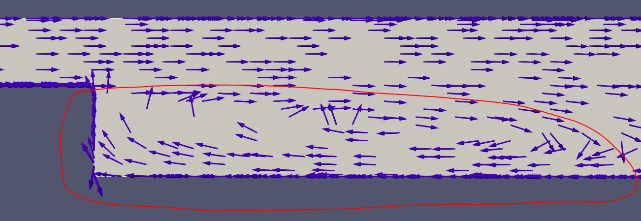
In a backward facing step, the flow separation occurs because of abrupt change in geometry.
Where Flow Separation happens ?
It happens after the step, near the corner formed by bottom wall and the step. The above image shows where the flow separation happens. Observe how the velocity vectors reverses their direction in the recirculation zone.
Animation of how the velocity contour plot converges.
Conclusion
1. As we decrease the mesh size, the results become more accurate and it produces smooth plots but the computation time increases.
2. As we decrease the mesh size, Converge decreases the time step as well to maintain the CFL number and to keep the solution stable. Because of that the number of cycles required for convergence increases.
3. Phenomena of Flow separation was studied for flow air over a backward facing step.