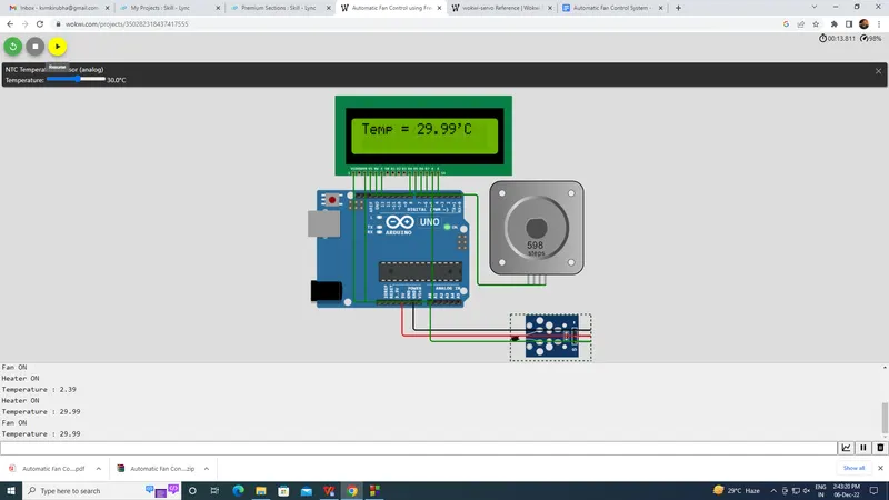
Automatic Fan Control System
Automatic Fan Control System
A standard air conditioning system either heats or cools the cabin depending on the position of the regulator. It is essentially a manual control of the temperature of the air pumped into the cabin, as well as the speed of the fan. The fan control systems operate with the same basic composition as in the manually controlled systems, such as the condenser, compressor, evaporator, and heater. The major difference is that it maintains a pre-set level of cooling or heating selected by the vehicle operator without manual intervention.
Features of the Fan Control System :
The automatic fan control system allows the vehicle passengers to set the desired temperature and set the system in AUTO mode. These values are taken as inputs by the fan control system and it then electronically controls the temperature and maintains them at user-specified values. This eliminates the human effort to regulate the cabin temperature by switching on/off the fan or by sliding warmer or cooler control. Fan control is essentially a more advanced computerized system, which basically automates everything and keeps the interiors of the car at the same temperature, irrespective of weather conditions outside. The system-integrated controllers work in tandem with the sensors to gauge the comfort and quality of the cabin air. This is accomplished by regulating the:
- Blower fan speed
- Heater tap activation
Some advanced fan control systems adjust some other aspects such as sunlight, dewpoint or rain detection in advanced systems. For example, when the sun load sensor detects bright light and high heat intensity, the fan speed increases to allow for a higher rate of cooling. Most fan control systems have a maximum setting also, which will automatically put the heater on full blast, usually so that the car's windscreen and windows can be cleared as quickly as possible in the event of fogging.
FreeRTOS Mutex with Arduino :
Resource management is a key factor in designing applications based on real-time operating systems . In RTOS, more than one task shares resources with each other such as peripherals, data, or external devices. Therefore, FreeRTOS provides a mutex semaphore to share resources between tasks securely and without data corruption. In this tutorial, we will learn to use mutex using FreeRTOS API and Arduino. Let’s start with the introduction of a mutex. After that, we will learn to use FreeRTOS mutex API with Arduino.
Mutex :
Mutex is a special type of binary semaphore that is used only for resource management between tasks. Resource management means it provides control access of resources between two or more tasks. The word mutex is also known as mutual exclusion.
In multitasking systems, there is a strong possibility that more than one task uses a single resource to complete their execution. But sharing a single resource between multiple tasks can cause multiple errors such as deadlocks, data corruption, priority inversion etc.
For example, we have two tasks in an RTOS application such as Task A and Task B and both tasks write a string on a liquid crystal display. Also the priority of Task B is higher than Task A. This means Task B can pre-empt Task A.
For instance, if a task starts to access a resource, but does not complete its access before being transitioned out of the Running state. If the task leaves the resource in an inconsistent state, then access to the same resource by any other task or interrupt could result in data corruption, or other similar issue.
FreeRTO Mutex API :
Before using a mutex, you must first create it using FreeRTOS mutex API. xSemaphoreCreateMutex() is used to create mutex. As we mentioned earlier, it is a type of semaphore. Therefore, Same FreeRTOS API functions are used to take and give back mutex.
xSemaphoreCreateGive()
xSemaphoreCreateTake()
xSemaphoreCreateMutex() is used to create mutex. We should also define a handle variable of type xSemaphoreHandle that can be used to reference mutex while taking and giving a token using the xSemaphoreTake() and xSemaphoreGive() macros.
SemaphoreHandle_t xSemaphoreCreateMutex( void );
It does not accept any input argument and only returns a Null or non-Null value. If it returns a non-null value that means mutex is created successfully and if heap memory is not available to create mutex, it will return a Null value.
Advantages :
The advantages of the fan control system are that the driver does not need to constantly be distracted from driving a car to adjust the fan equipment. The electronics themselves take measurements and depending on the initial setting,
turn on or off the necessary system (heating/cooling). An additional benefit of the fan control system is a self-diagnostic function which when used will greatly reduce the time spent locating system faults.
//Structure Queue - v1
// Include Arduino FreeRTOS library
#include <Arduino_FreeRTOS.h>
// include LCD library function
#include<LiquidCrystal.h>
// include Stepper Motor function
#include <Stepper.h>
const int stepsPerRevolution = 200;
//Define Stepper Motor Pins
Stepper myStepper(stepsPerRevolution, 6, 7, 8, 9);
//Define LCD pins
LiquidCrystal lcd (12,11,2,3,4,5); //RS, E, D4, D5, D6, D7
// Include semaphore support
#include "semphr.h"
// Define a struct
SemaphoreHandle_t xMutex; //Declare mutex handle
void setup()
{
Serial.begin(9600); //Enable serial communication library.
lcd.begin(16, 2); //Enable LCD library
myStepper.setSpeed(60); //Enable Stepper Motor library
pinMode(A0, INPUT); //Enable A0 Pin from analog input
xMutex = xSemaphoreCreateMutex(); //Create a MUTEX
xTaskCreate(TaskLcd,"Displaydata",128,NULL,1,NULL);
xTaskCreate(TaskFan,"Fan_ON",128,NULL,1,NULL);
xTaskCreate(TaskHeater,"Hearter_ON",128,NULL,1,NULL);
//Create Task to perform
vTaskStartScheduler(); //start the scheduler
}
void loop(){}
void TaskHeater(void *pvParameters) //task heater function definition {
int temp = 0;
for (;;)
{temp = analogRead(A0); //read the analog input
if(temp>512)
{
xSemaphoreTake(xMutex, portMAX_DELAY); //take the mutex source Serial.println("Heater ON"); //turn ON the Heater
myStepper.step(-stepsPerRevolution);
delay(500);
xSemaphoreGive(xMutex); //give back the mutex for other task }
vTaskDelay(pdMS_TO_TICKS(1));
}
}
void TaskFan(void *pvParameters) //task fan function definition {
int temp = 0;
for (;;)
{
temp = analogRead(A0);//read the analog input
if(temp<512)
{
xSemaphoreTake(xMutex, portMAX_DELAY);//take the mutex source Serial.println("Fan ON"); //turn ON the Fan
myStepper.step(stepsPerRevolution);
delay(500);
xSemaphoreGive(xMutex);//give back the mutex for other task }
vTaskDelay(pdMS_TO_TICKS(1));
}
}
void TaskLcd(void * pvParameters) //task LCD function to display LCD {
float tmp = 0;
int temp = 0;
for (;;)
{
xSemaphoreTake(xMutex, portMAX_DELAY); //take the semaphore
temp = analogRead(A0); //read analog input
float tmp = 1 / (log(1 / (1023. / temp - 1)) / 3950 + 1.0 / 298.15) - 273.15;
Serial.print("Temperature : ");
Serial.println(tmp); //print the temperature in Serial monitor
lcd.setCursor(0, 0);
lcd.print("Temp = ");
lcd.setCursor(7, 0);
lcd.print(tmp);
lcd.print("'C");
delay(500); //print the temperature in LCD
xSemaphoreGive(xMutex);
vTaskDelay(pdMS_TO_TICKS(1));
}
}