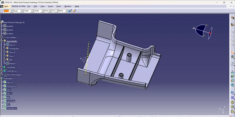
Attachment Feature Creation (Ribs & Screw Boss)
( DOOR HANDLE )
Step 1:* Creating Tooling Axis
- Go to insert (Geometrical set) - parent (Door handle) and then ok, then define the tooling axis.
A. Creation of point
B. Creating a line in z-axis
C. Making that line into tooling axis with required colour and thickness.
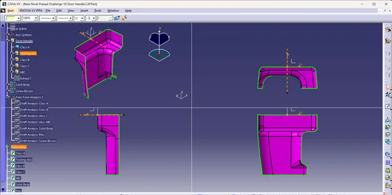
* Performing draft analysis for calss A
- Insert (Analysis) and click on the Feature Draft Analysis to perform
- Drag the compass towards the tooloing axis and adjust the compass then click on the surface of the body at any where and then ok.
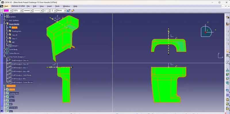
* Then publish the tooling axis
- Click on tools and publication , then select the tooling axis and publicate.
Step 2:* Creation of Class B
- Insert (Geometrical set and name it as class B under Door Handle.
- Then, offset the entire class A and give offset of 2.5mm and then click on ok.
- We will get a incomplete profile at one edge.
- To close that particular hole.
- Use Multisection solid select that particular edges of role and then give guided boundary and close that particular hole.
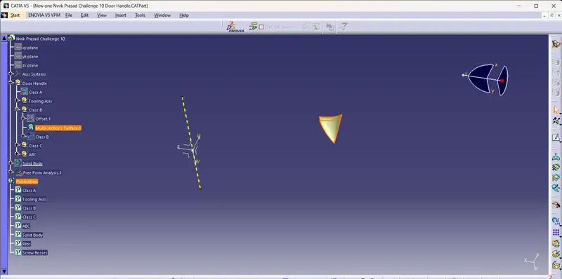
- Then use join command to join the closed hole to the surface.
* Perform Draft analysis for class B by following draft analysis procedure for previously done.
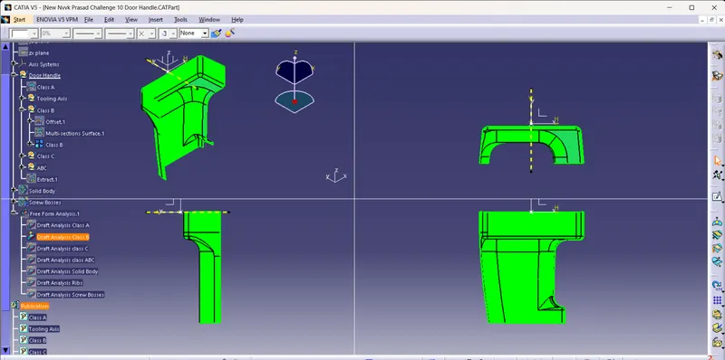
* Then publicate the class B by selecting tools,publication and select class B and Publish.
Step 3:* Creation Class C
- Insert a new Geometrical set and name it as class C under Door handle.
- Use boundary commands and get the boundaries of one particular side , then use Sweep command to get the class C surface at one side and also use some length and give it accordingly to get a particular shape.
- Then join the created surface to the class B.
- Then join the created surface to the class B.
- Then use Boundary command and create the boundaries of another side by selecting thie particular points and create boundary, give lengthand create surface of class C.
- Then extrapolate the non contacted joints and use trim command to join them together.
* Perform Draft Analysis on Class C
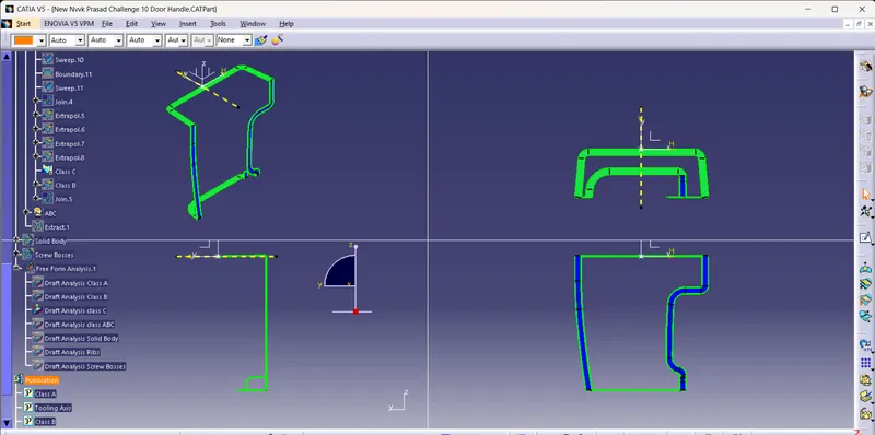
- Insert (Analysis) and click on feature draft analysis to perform.
- Drag the compass towards the tooling axis and adjust the compass then click on the surface of the body.
- Use join command lastly to join the C surface with the B class.
* Then publish the Class C
- Click on tools and publication , then select the Class C and publish.
Step 4:* Creation of ABC
- Join ABC classes accordingly
- Use extract command and extend the Class B surface and trim it accordingly to get the contact between the class B and Class C.
- Join the ABC classes according to create a closed hollow surface.
* Perform Draft Analysis on Class ABC
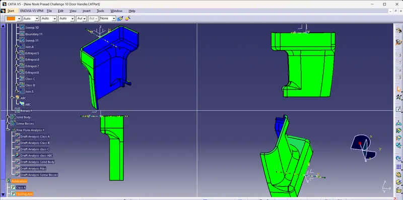
- Insert (Analysis) and click on feature draft analysis to perform.
- Drag the compass towards the tooling axis and adjust the compass then click on the surface of the body.
- Use join command lastly to join the A, C surface with the B class.
* Then publish the Class ABC
- Click on tools and publication , then select the ABC and publish.
Step 5:* Creation of Solid Body
- Then after creating the ABC Classes. Insert a part body, name it as solid body.
- Go to part design and use closed surface command to create solid body and select the body.
* Perform Draft Analysis on Solid Body
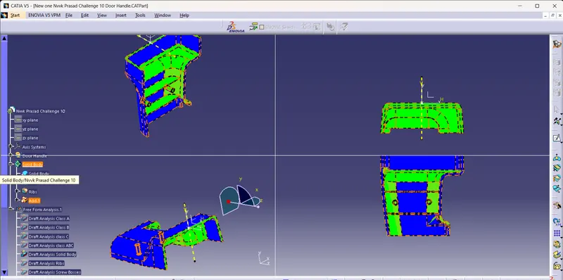
- Insert (Analysis) and click on feature draft analysis to perform.
- Drag the compass towards the tooling axis and adjust the compass then click on the surface of the body.
* Then publish the Solid Body
- Click on tools and publication , then select the ABC and publish.
Step 6:* Creation of Ribs
- Define the part body select the top view and click on positioned sketch.
- And draw two lines to create ribs,constrain them accordingly.
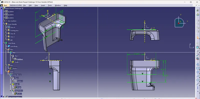
- Exit from the work bench and pad it to accordingly by the given information.
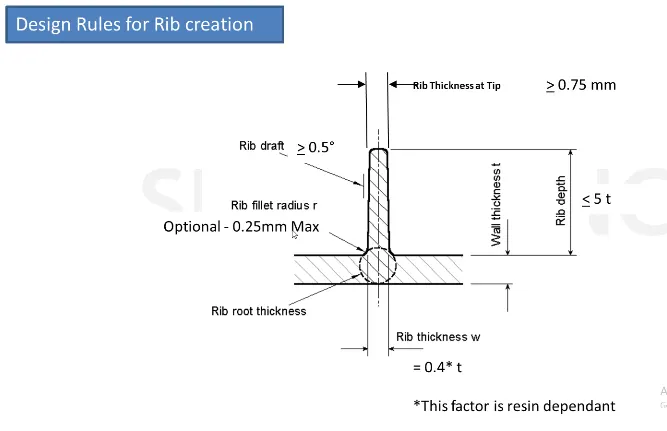
- Create rectangular plates with the neutral thickness and use fillet of (0.25mm)
- Use Draft command and give draft angle of (0.5 Degrees) with respect to the tooling axis.
* Perform Draft Analysis on Ribs 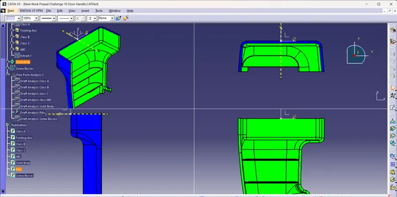
- Insert (Analysis) and click on feature draft analysis to perform.
- Drag the compass towards the tooling axis and adjust the compass then click on the surface of the body.
* Then publish the Ribs
- Click on tools and publication , then select the Ribs and publish.
Step 7:* Screw Bosses
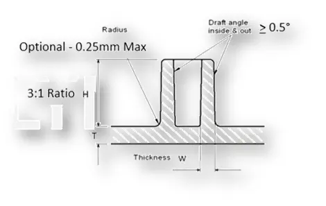
General Guidelines for Bosses:
- Draft - 0.5 degrees on the walls of boss
- Thickness - Typically 40%* of the nominal wall at the base.
- Height to Diameter Ratio - 3:1
- Radii - 0.25mm maximum radii.
- Insert new part body and name it as Screw Boss.
- Select the top view and select positioned sketch draw the circles with dimesion accordingly and constrain them,
- Pad upto the given height by considering design conditions.
- Use Draft command and draft from bottom to up with (0.5 Degrees) with the reference of tooling axis.
- Use fillet command and fillet it at top and bottom.
- Create the screw bosses accordingly.
* Perform Draft Analysis on Screw Bosses
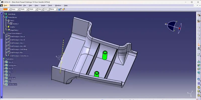
- Insert (Analysis) and click on feature draft analysis to perform.
- Drag the compass towards the tooling axis and adjust the compass then click on the surface of the body.
* Then publish the Screw Bosses
- Click on tools and publication , then select the Ribs and publish.
* Tree Structure and Publications :