Aston Martin ONE-77 Challenge-11 (Project)
Title: Surface Modelling of Aston Martin One-77 using Solid works.
Objectives:
- Learning solid works from intermediate to advance modelling.
- Surface modelling in depth level approach.
- Basic concepts of surface modelling.
Introduction:
Solid works is a platform for computer aided design (CAD) and CAE. It is one of the ost widely used platforms acroos the world due to its flexiblity and number of design features put together in use, surface modelling is a methodology of creating products using various surfcae features. The overall combination of sold models along with surface models helps us to achieve the real view of objects. Most of the transportation systems including sports cars are built using surface approach as a design perspective. The model designed in this project is Aston Martin One-77.
The Aston Martin One-77 is a two-door, two-seater flagship sports car built by the British car manufacturer Aston Martin. The car was first shown at the 2008 Paris Motor Show, although it remained mostly covered by a "Savile Row tailored skirt" throughout the show. It was revealed in full at the 2009 Geneva Motor Show, and deliveries from the beginning of 2011.
The production of the One-77 was limited to 77 cars, forming part of the name One-77, and sold for GB£1,150,000. In May 2012, one of the 77 was involved in a crash in Hong Kong and was written off, reducing the number of total cars in existence to 76.
Features used:
Most of the Features used in creating this models are surface modelling features:
- Projected Curve: This type of feature is used for creating a projected curve out of two curves in 3d work space, this curve can be used as a guide curve for a sweep or in case a boundary surface or surface loft to create surface.
- Surface extrude: This kind of feature is used to create extrude surface.
- Surface Loft: The surface loft features is used to create a surface in three dimmensional space which is guided by many curves according to direction, the feature is similar to boundary surface.
- Surface trim: This feature is used to split the surfaces.
- Boundary surface: This surface is similar to boundary surface various constraints as tangent to surface, normal to profile and direction vector.
- Surface Extend: This used to create an extended surface with edge as refrence.
- Surface fill: This is used to fill the surface between edges.
- Split Line: This method is used to create on split line on surface, this will act as a individual surface or face.
- Sketch Tools: Both 2D and 3D Sketch can be created out of this great tool one of the most important tools like spline, circle, rectangle, corner rectangle and construction line can be used to genrate sketches in the various plane as well as 3D space.
- Surface Knit: This particular feature is most commonly used to knit all the surface together and convert all of them into one body.
- Surface offset: This particular feature is used to create surfcace above or below another surface with a offset distance.
- Face Delete: This particular feature is to delete a particular face from a body, this particular feature also has further options to delete and patch or delete and fill.
- Cut with surface: The cut with surface is also great tool to cut with a surface through a solid body.
- Surface sweep: The surface sweep is also like solid sweep the only difference is that in this case it genrates a surface,
- Move body: This particular tool is used to move a solid body from one particular point in 3D space to a certain point in space defined by x, y, z, coordinates, it is also used to rotate a certain body by some degree around axis.
- Refrence Geometry: This particular tool is used to create various refrence geometry like plane and axis in refrence to to the standard planes like top planes, front plane and right plane.
- Ruled surface: The ruled surface is used to genrate surface specified in a particular direction for example add tangent extension to complex surfcaes.
- Fillet: Fillet is a tool that enables us to smoothen the surface on a surface body and hence genrate a smooth finish there are various types of fillet one can use like variable fillet or round fillet, face fillet etc. In this case we will be using variable fillet and rounded edge fillet.
Project Flow:
The most important aspect about the project is to understand the flow it sets the benchmark on how well we are able to understand the design process.
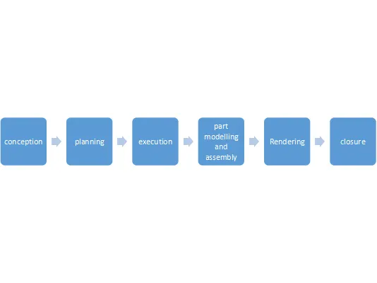
Design Methodology:
- Blueprint Setup.
- Design of roof.
- Design of sides and fenders of aston martin.
- Design of front and rear bumper.
- Design the hood sub assembly and the rear bumper.
- Design the Grills and lights.
- Design the wheel tires and well knitted mirrored body.
- Assembly of the car body and rendering.
- Blueprint Setup:
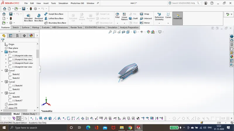
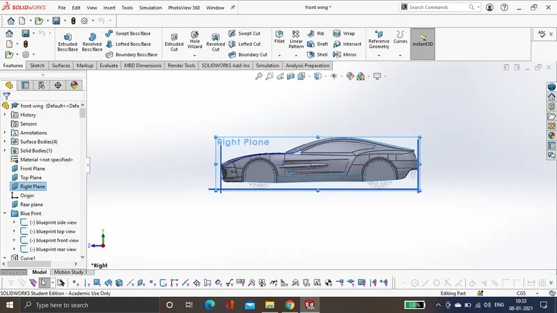
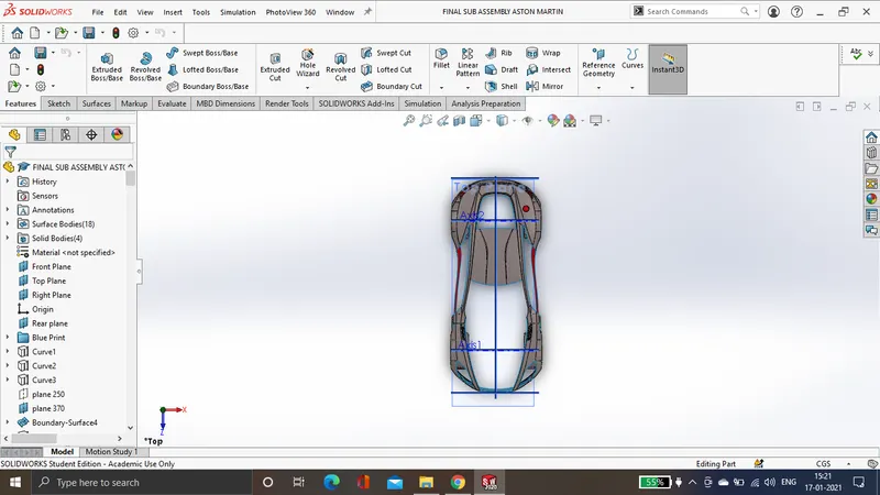
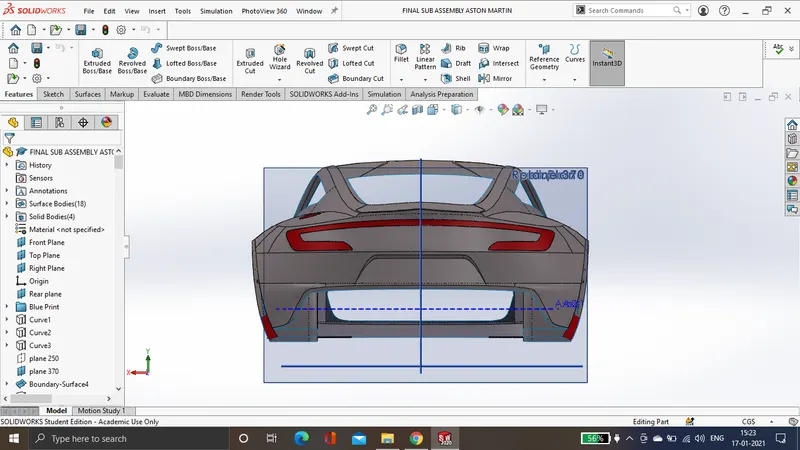
The blueprint setup consist of the basic sketches of the car and all its views are setup in various planes it is drwan using sketch pictures, which is one of the sketch tools. The blue print helps us to trace the design of each and every component and also with designing basic features of various complex surfaces.
- Design of Roof: The method of designing roof is based on the feature boundary surface. The roof of car is a portion of an automobile that proteccts the car from wind, rain, sun and other external elements.
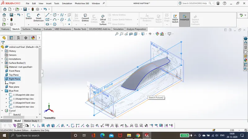
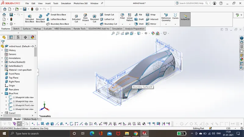
- Design of fenders and sides of aston martin.
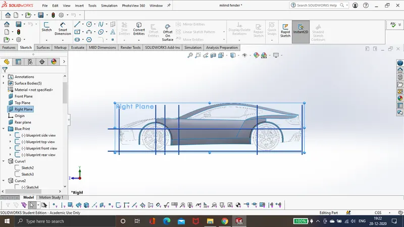
The above feature is designed using boundary surface and projected curve. In the further steps we use surface trim to create a space for the wheels to accomodate.
- Design of front and rear bumper:
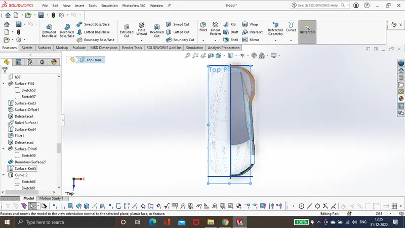
- Design of Hood and sub assembly:
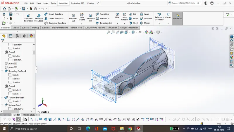
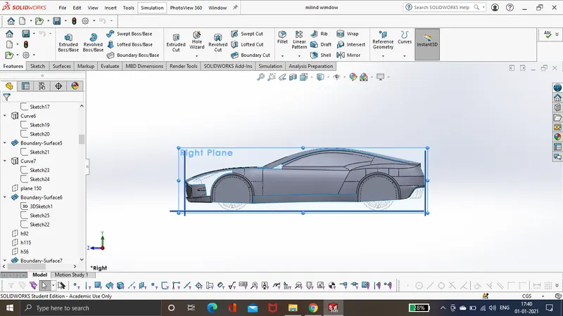
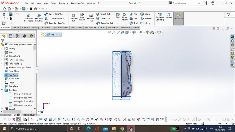
The particular part was designed using surface trim, particular sketchhes where drawn on top plane and where used as surface trim option, we also use split line 0cm surface offset method to seprate individual parts, like seprating car doors windows etc.
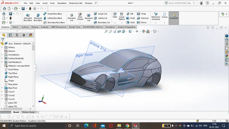
- Design of grills and lights:
The surface offset method is one of the best methods to offset a surface from the surface body and generate the refrence for the same solid body, we can use this particular surface as a refrence to genrate solid objects and add features to them all the below sub assemblies like the surface door, front lights where generated vis using this particular method.
The below are the images of windshield, side window , rear window and grilles which where converted to solid bodies via using the bove method.
Basic car Model:
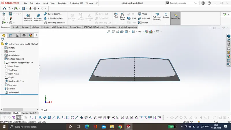
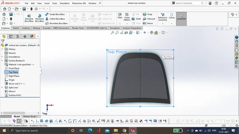
- The above image represents front glass pannel, It is a surface body with clear glass transparent view attached to it. In a similar manner we design the rear window pannels.
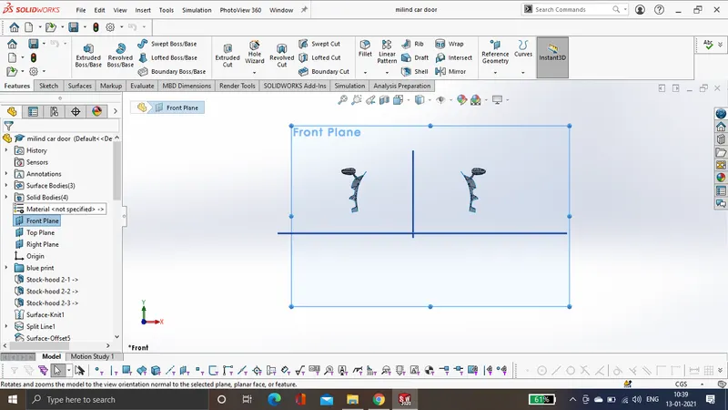
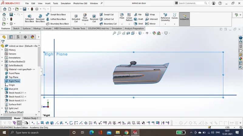
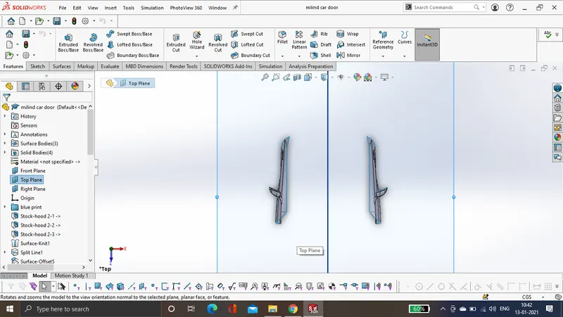
- The below are the images of side window pannels and surface doors.
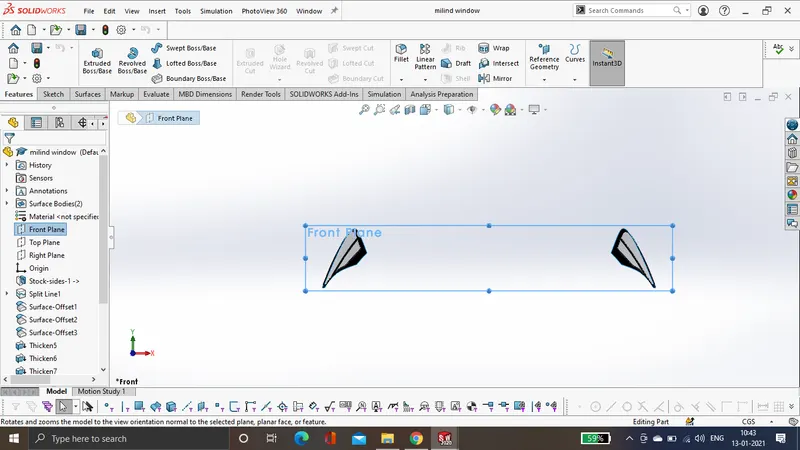
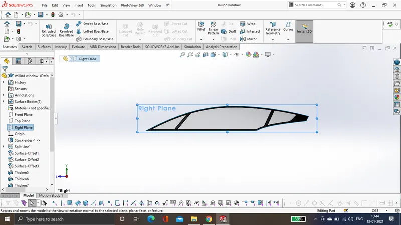
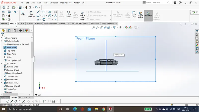
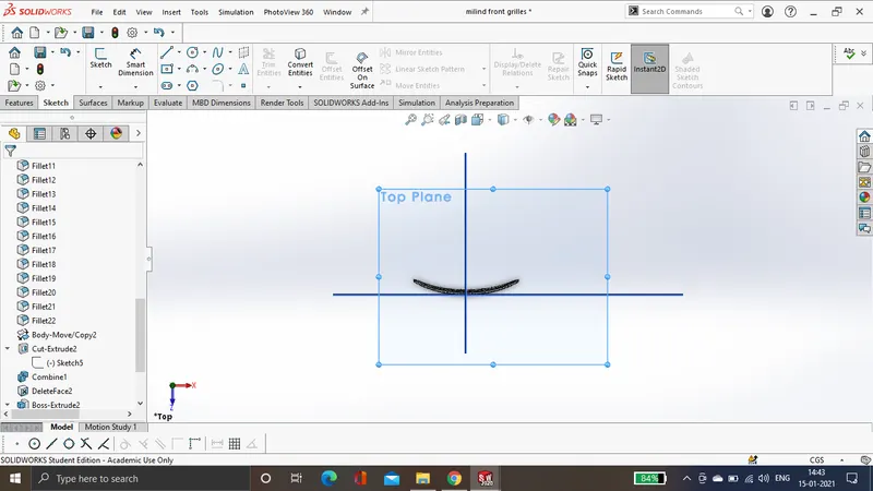
The below are the images for the front grilles and front lights.
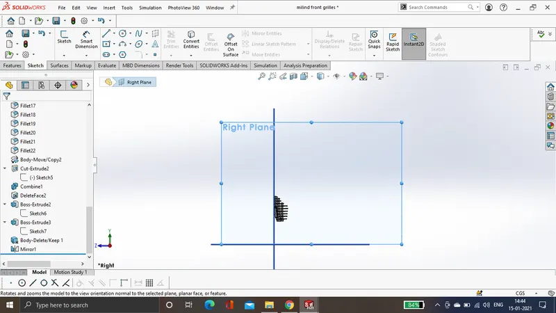
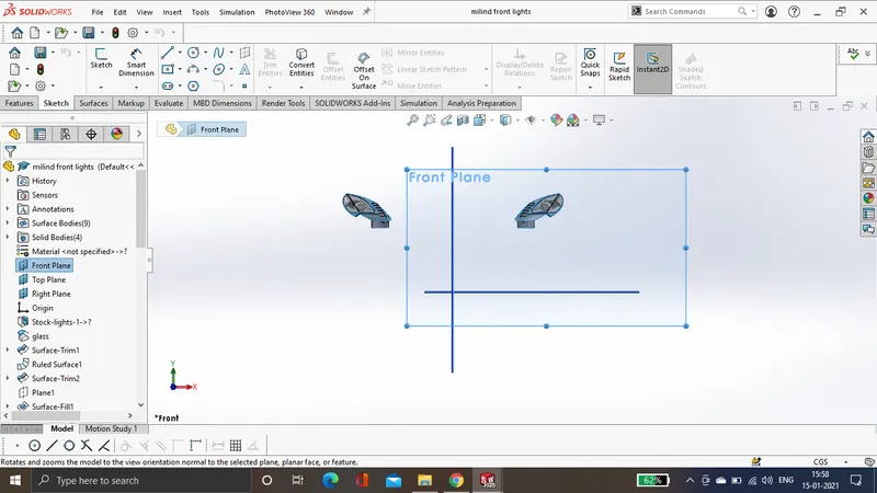
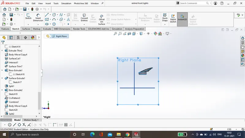
- The below are the images of rear bumper.
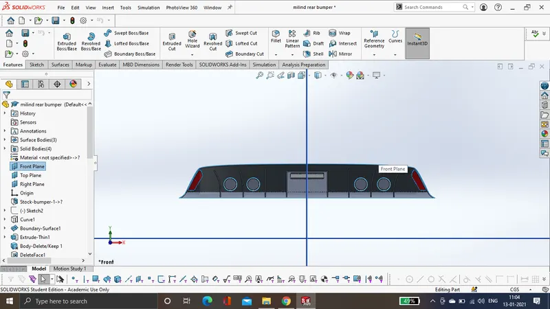
- Features used in solid modelling.
- Boss/base extrude :This particular feature is used to create a solid geometry out of a 2D sketch on plane.
- Revolve Boss/Base: This particular feature is used to create a revolved geometry out of sketches there are two profiles one the profile we want to give a revolve and other guide curve
- Intersect: This is agreat feature to combine solid bodies and remove the unwanted solid body from it.
- shell: The shell feature is used to create a hoolow geometry within a solid body.
- Mirror: This particular feature is used to mirror the bodies, surface features etc by using any of the planes as a refrence in this project we have mirrored most of the solid bodies across the right plane.
- Combine: This particular feature is used to combine all the solid bodies into one particular solid body.
- Fillet: This particular feature is used to sharpen all the smooth edges of a particular body.
- Cut with surface: this particular tool is a great tool to create a smooth finishing on the face of solid body or to remove material from the face via using surface.
The folllowing are the images of rims, tyre and and assembly of brake, disc.
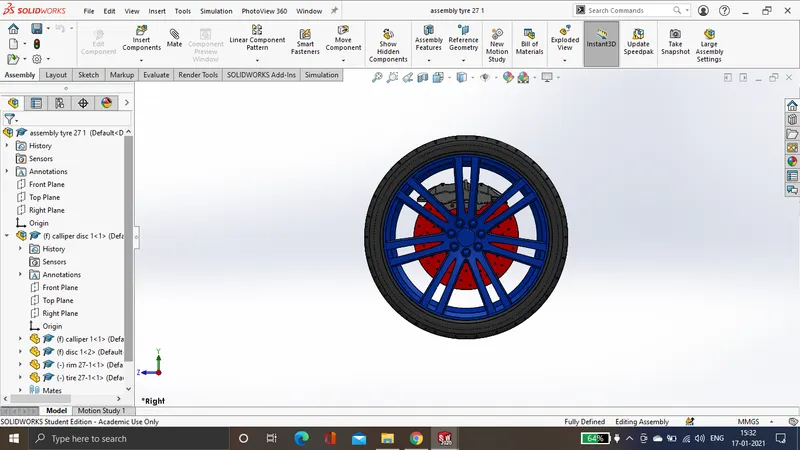
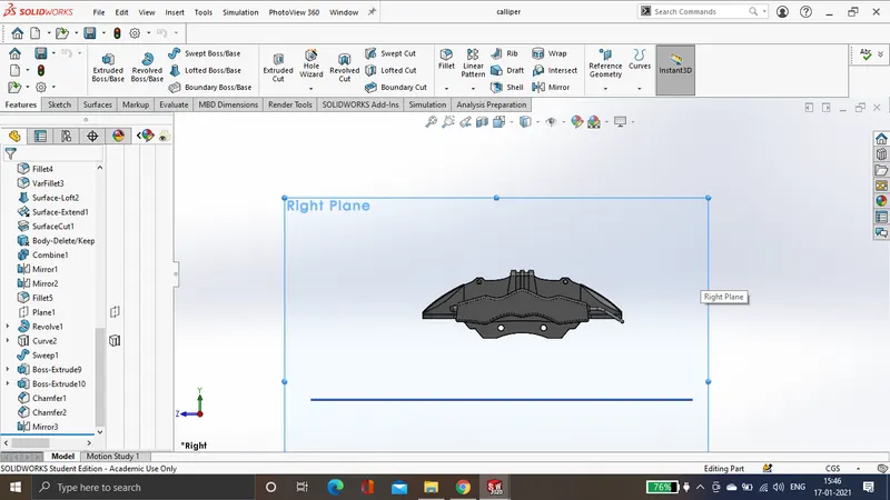
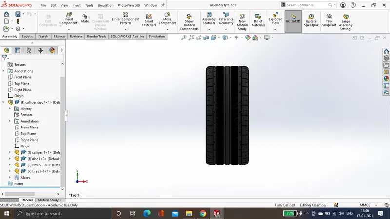
There are two types of tyres with different widths which are 27 cm and 34 cm.
- Final assembly:
The final assembly was carried out in solid works using a new assembly and applying mates, the below are the images for refrence. Coincident mates where applied for the parts to make them fixed.
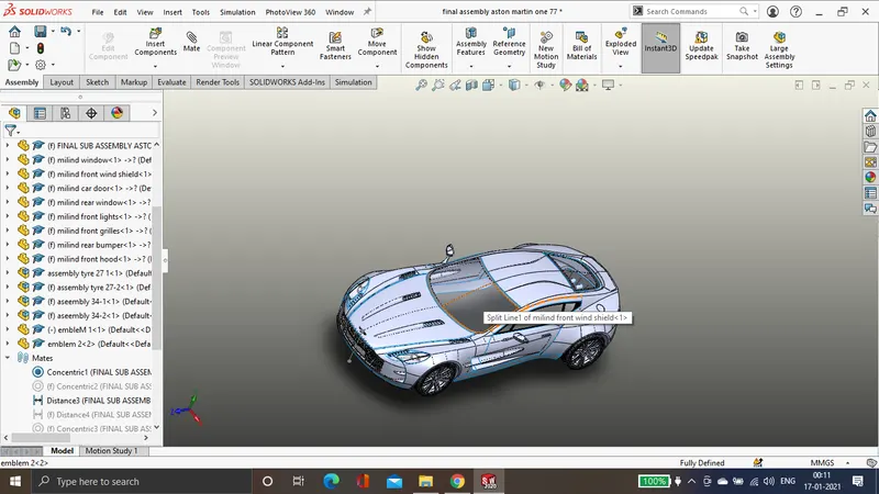
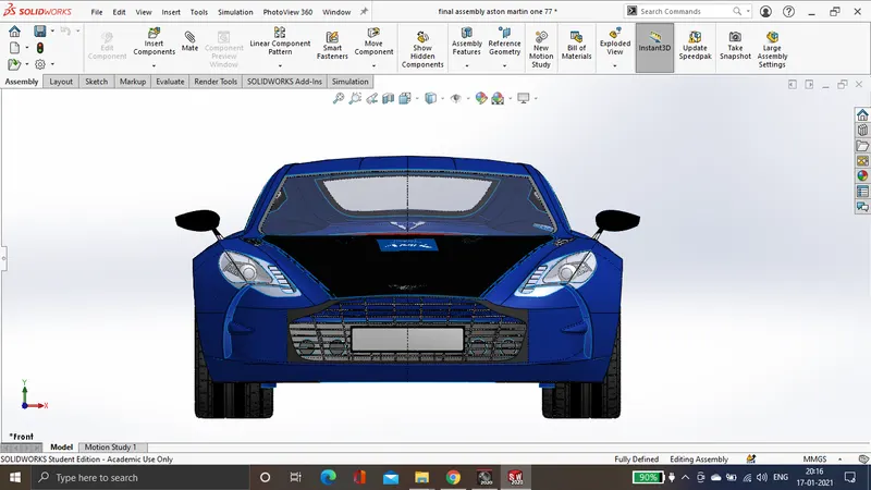
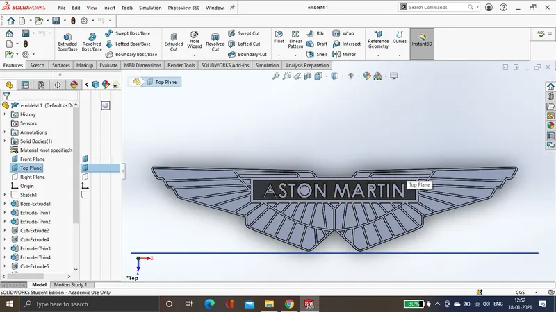
Emblem of the car was designed as a individual solid body.
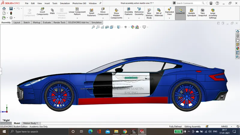
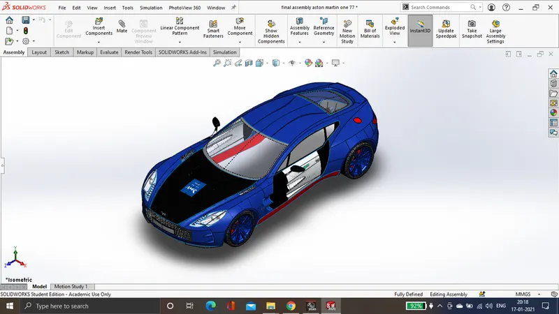
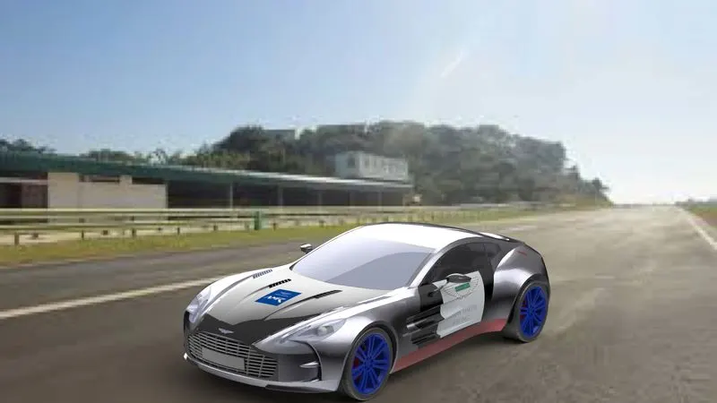
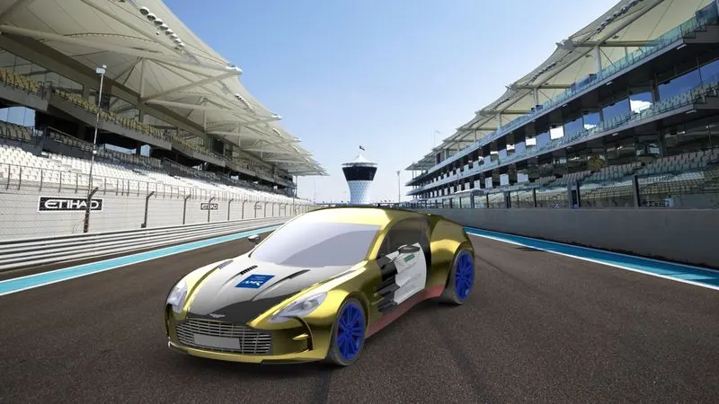
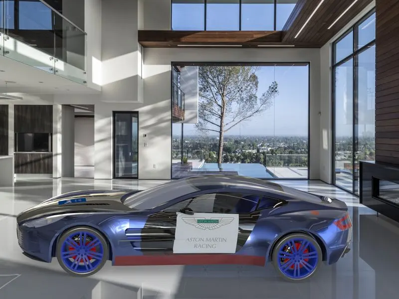
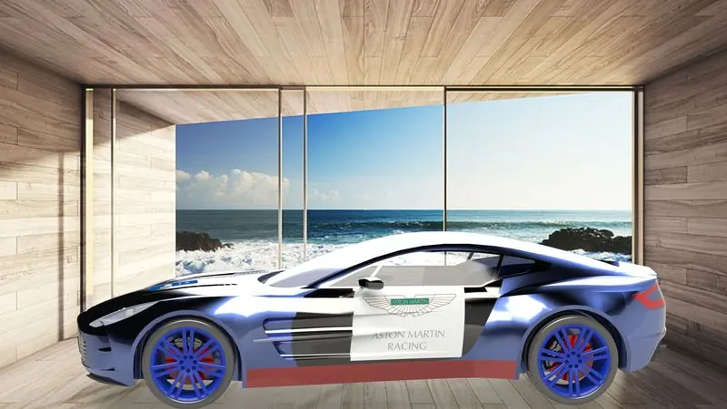
- Rendering: The process of rendering is to give the product a photo realistic appeareance in the surrounding, various lights, studio scenes and background may be added to make the object more realistic for the current project the following are the rendered images for the product.
- Conclusion: The following project gives us in depth review about complex surface modelling and how to tackle with various problems involved in modelling this particular surfaces.