Aston Martin ONE-77 Challenge-11 (Project)
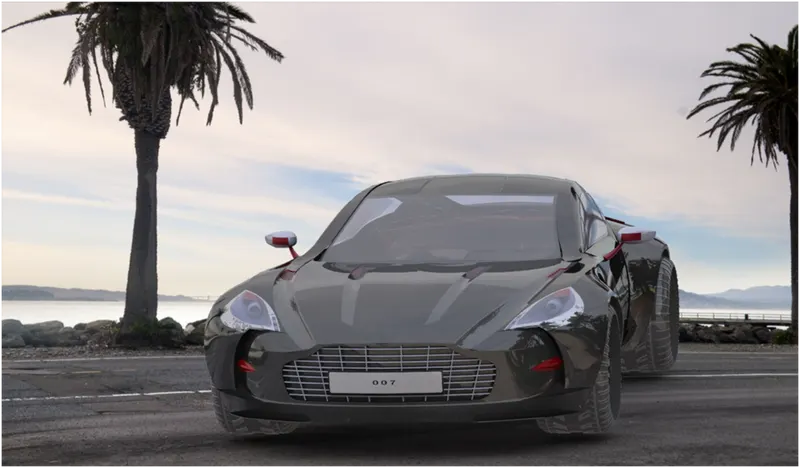
Aston martin one 77
Title of the Project: Surface modeling of Aston martin ONE 77 using Solid works
Objective:
The main objective of this project is to create a detailed surface model of the Aston martin One 77 car. W3e will assemble all the different parts of the car to create a full model.
Introduction
The Aston Martin One-77 is a two-door, two-seater flagship sports car built by the British car manufacturer Aston Martin.
The car is a rear beauty as only 77 of these were produced by the company.
The car was first shown at the 2008 Paris Motor Show, although it remained mostly covered by a "Savile Row tailored skirt" throughout the show.[2] It was revealed in full at the 2009 Geneva Motor Show, and deliveries began in 2011.[3]
The production of the One-77 was limited to 77 cars, although several development cars were made for engineering, testing, and marketing.
The One-77 features a full carbon fibre monocoque chassis, a handcrafted aluminium body, and a 7.3 L; 446.2 cu in (7,312 cc) DOHC 4 valves per cylinder V12 engine with Variable Valve Timing rated at 559 kW (760 PS; 750 hp) at 7,500 rpm and 750 N⋅m (553 lb⋅ft) of torque at 5,000 rpm. Aston Martin claimed the engine to be the most powerful production naturally aspirated engine in the world when the first car was delivered.[9]
The car utilises a 6-speed automated manual transmission from Graziano Trasmissioni and height-adjustable pushrod suspension coupled with dynamic stability control.[10] The One-77 features Pirelli P Zero Corsa tyres (255/35 ZR20 front, 335/30 ZR20 rear) and Carbon Ceramic Matrix brakes.
The top speed was estimated to be 350 km/h (220 mph) but actual tests in December 2009 showed a figure of 354.067 km/h (220.007 mph),[11] with a 0–97 km/h (60 mph) acceleration time of approximately 3.5 seconds.
The engineering and manufacturing of the carbon fibre chassis and suspension system was contracted to Multimatic of Canada. The projected weight was 1,500 kg (3,307 lb),[12] but the production model weighs 1,630 kg (3,594 lb).
The most exclusive Aston Martin of the 'Gaydon era', One-77 was limited to 77 unique examples. Tantalisingly, the first glimpse the world got of the One-77 hypercar was a maquette of the new car at the 2008 Paris Motor Show, three quarters covered by a grey pin-stripe fabric cover with only a glimpse of the front right side coyly peeping out. The full picture was revealed at the March 2009 Geneva Motor Show, where a metallic blue mockup and rolling chassis with its entire powertrain were on display.
AUTOMOTIVE ART
The finished car made its bow in late April 2009 at the Concorso d'Eleganza Ville d'Este on the shores of Lake Como, winning the design Award for Concept Cars and Prototypes.
SPECIFICATIONS
Engine:
7312 cc V12, Alloy quad overhead camshaft, 48-valve
Brakes:
Front ventilated carbon ceramic discs, 398 mm diameter with six-piston calipers Rear ventilated carbon ceramic discs, 360 mm diameter with four-piston calipers
Top Speed:
220+ mph
Transmission:
6-speed manual with optional 5-speed automaticRear mid-mounted, six-speed automated manual gearbox with auto shift manual/select shift manual (ASM/SSM) electric hydraulic control system
Weight:
1630kg
0 – 60 mph:
>3.7 sec
The whole project contains in depth study and analysis of the surfaces and the surface flow of the car that we will be creating.
Solidworks student version was used to make this particular project
This project contains all the surfaces modeling as well as the solid modeling of the car to provide the rendering of the whole outer body of the car
The solidwork will alow us to create the parts which can be created to make the whole assembeley brief about parts and assembely;
- Parts
The Part section includes a variety of workbenches, including sketch, solid, and surface.
Create a new part file and hide the planes to begin. Place a plane at a particular distance from the front plane as well. There are two sorts of sketches on the sketch workbench, as well as a range of other sketching tools.
We may use the tools provided under 2D sketch to generate 2D drawings. There are a variety of useful tools available, like the line, rectangle, and other sorts of tools. We may also make 3D drawings, which are commonly used to make curves between surfaces.
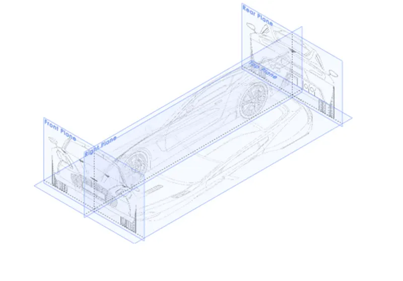
Using sketch, add blueprints of the automobile to the planes and scale them appropriately. We may begin drawing after uploading the blueprints. The plans show the car's front, side, top, and back views.
We utilised sketch tools to create projected curves and surfaces in this project. We need two drawings from two distinct planes to construct the projected curves. The projected curve is a result of the merging of two drawings.
Boundary surfaces, extruded surfaces, revolved surfaces, swept surfaces, lofted surfaces, and filled surfaces are used to create the surfaces.
tools for working on the surface Fillet, offset, delete face, trim surface, knit surface, split line, thicken, and other tools were also utilised in this project.
Boss/base, cut, and a variety of additional tools are among the tools included in this ribbon. Extruded, revolved, swept, lofted, and boundary boss/base are just a few of the tools available in the boss/base segment. Extruded cut, revolved, swept, lofted, and boundary cuts are among the tools available in the Cut ar
When constructing a surface with two directions, i.e. four curves or sides, the boundary surface tool is utilised. As the name implies, the Fill Surface tool aids in the creation of surfaces with more than four edges in three or more directions. Edge surfaces for tail lights and spoilers are likewise created with the ruled surface tool.
The features ribbon is the second ribbon we utilise inside the component section. There are several tools inside this ribbon that we may employ.
forming solids
- ASSEMBLY
The assembly section may be used to align the various pieces that have been constructed. After putting the part files into the workspace, they may be aligned using various mate choices.
Male alternatives such as coincident, concetric, and distance mate are the most popular.
The coincident mate is employed on planes, and we'll use it to mate each plane. Each plane is positioned in relation to the primary plane.
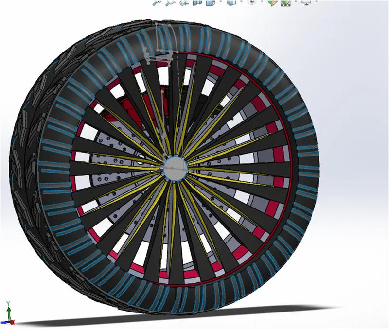
The wheel assembly is aligned with the main body using the concentric and distance mates.
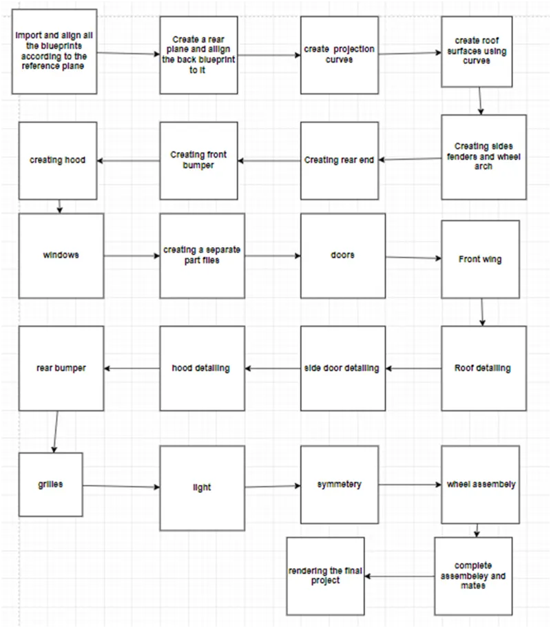
Design methodlogy :the design process can be summarized by this design flow chart
Import and align all the blueprints according to the reference plane :
Blueprints are one of the most useful things for modelling a car using any 3D software.
They are basically orthogonal drawings of the car in every direction (front, top, side and rear). They allow us to draw curves over a picture so that we can be precise and match the real shape of the car.
Click here to download your blueprints
Open a new part
Open SolidWorks, go to File > New
Select the part icon and click OK.
This part will be the main file of the tutorial. Most of the modelization process will take place here.
Change the units
When creating a new part in SolidWorks, the default unit system is set to millimeter, grom, second.
For this tutorial, we will need to change it to centimeter, gram, second.
Locate the options icon (it looks like a gear) at the very top of the screen.
Go to the Document Properties tab then click on Units
Check the CGS unit system.
Untick the Lock aspect ratio box and fill in the left-hand side section with the parameters present in this screenshot For convenience, add some transparency to the image so that we can see the car's model through the blueprint later on. You may rename this sketch Side BP by slowly double-clicking on the sketch, or by hitting the F2 key once you've selected
.Click OK to validate.
Exit the sketch by clicking on the icon in the top-right corner of the viewport, or by clicking on the Exit Sketch icon at the left of the Command
create projection curves
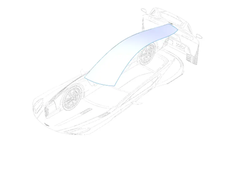
Sketches 6 and 7 will be used to build a 3D profile using the following projected curve.
Select both sketches and go to Insert > Curve > Projected
Leave everything as default, and click OK. ✔
There is now a 3D curve visible in the viewport!
Use this to create the curves by using boundry surface tools
Time to add our first surface!
Go to Insert > Surface > Boundary Surface
As you can see in the left-hand side menu, this surfacing tool requires two sets of objects, namely Direction 1 and Direction 2. They refer to the directions of the profiles used to create the surface.
Imagine a square like this one.
All the edges that go in the same direction (that is to say parallel in this example) are part of the same set.
The idea is the same with the roof's surface that we want to build.
The sketch on the side plane and the long projected curve we created are going in the same direction, whereas the other short profiles, be it the two projected curves or the two 2D profiles in the middle, are going in the perpendicular direction.
Similarly we will be creating fenders and side surfaces and rear end
Using projected curves and fill surface
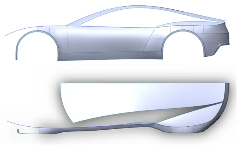
Tools
extrude
Create the Base Feature with an Extrude Before you create an extrude feature, you need to make a sketch. The sketch begins at the origin, the (0,0) coordinate of a 2D sketch. The origin is a helpful reference point for sketches. If you begin a sketch at the origin, the sketch position is set. When you add dimensions and relations to the sketch, it becomes fully defined. After you sketch the rectangle, use the Extrude tool to create a 3D base feature. The sketch is extruded 34mm normal to the sketch plane. This model is displayed in an isometric view so you can see the model structure. To design a 3D model, first make the 2D sketch, then create the 3D feature.
Add an Extrude to the Base The second extrude adds material to a part by building upon the base. In this example, you extrude two of the countertop edges. 39 Parts First, you create the sketch for the extrude with the Convert Entities tool. The Convert Entities tool lets you create a sketch by projecting a set of edges onto the sketch plane.
In this example, the left and upper edges are projected. Next, you use the Extrude tool to create the countertop edges.
Cut-Extrude
The Cut-Extrude tool is similar to an extrude feature, except that it removes material from the model instead of adding material. First you create a 2D sketch, then you make the cut-extrude. In this example, you use the Ellipse tool to make an oblong sketch. When the cut-extrude is complete, the countertop has an opening for the sink. 40 Parts For a lesson that includes extrude features, see the Lesson 1 - Parts tutorial.
loft
Use a Loft to Make a Solid After you make the cut-extrude feature, you create the sink with the Loft tool. A loft creates a feature by making transitions between two or more sketch profiles. When you create a loft, the sketch profiles must reside on different planes (or planar faces). In this example, the loft creates the sink by connecting an elliptical sketch and a circular sketch. First, create a sketched ellipse on the bottom of the countertop with the Convert Entities tool.
This tool creates a sketch by projecting the existing ellipse from the Cut-Extrude onto the bottom of the countertop. Second, create a new plane, Plane1, by offsetting it from the Top plane. Plane1 is parallel to the Top plane. Next, use the Circle tool to sketch a circle on Plane1. Now that you have two sketch profiles, use the Loft tool to connect them. The SOLIDWORKS software uses a shaded preview to illustrate what the model will look like before you accept the feature. 41 Parts For a lesson on lofts, see the Lofts tutorial. Shell the Part Because the loft creates a solid feature, you need to cut out material to make the sink. The Shell tool hollows out the sink and removes the top face. When you shell a part in SOLIDWORKS, selected faces are removed and thin faces remain on the rest of the part. For a lesson that includes shells, see the Lesson 1 - Parts tutorial.
Fillets
To complete the countertop, you round off sharp edges by adding fillet features to the model. When you create a fillet, you set the radius to determine the smoothness of the edges. It is best to save cosmetic fillets for the last step, after all of the geometry is in place. Models rebuild faster when fillets are made at the end of the design process. Fillets are applied features, not sketch features. This means that fillets do not require you to create a sketch. Instead, you select the edges of an existing feature, set the fillet radius, and create the fillet. As you increase the radius, the edges or faces become rounder.
Create the Sweep
The faucet base is made from two extrude features. After you create the two extrudes, the model appears as shown. Use the Sweep tool to make the spigot by Sweep preview: projecting a profile along a path. In this example, the profile is a circular sketch, and the path is a sketched arc and a tangent vertical line. The circular profile remains the same shape and diameter for the entire
Revolve the Sketch
Create the First Revolve A revolve creates the base of the handle, and completes the first feature in the faucet handle. First, you create a sketch with the Line and Spline tools. In some cases, you can add an axis of revolution with the Centerline tool. A centerline creates an axis that is construction geometry; it is not built into the feature.
Creating separate parts
Separate parts which we have to create to make the parts and work in details
Parts are :
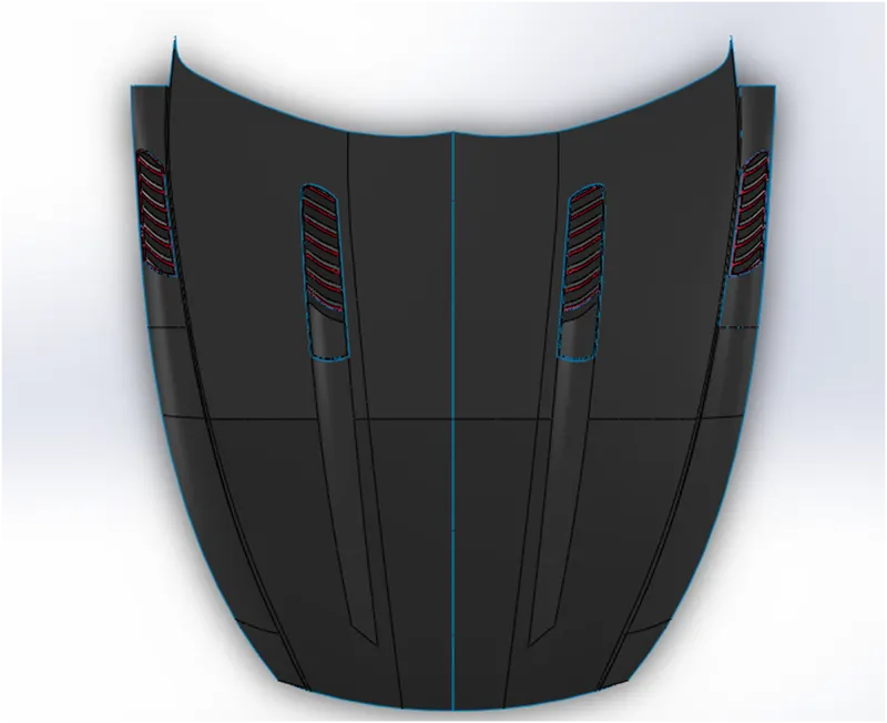
Hoods:
Wheels:
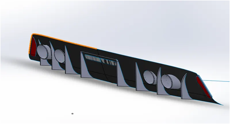
Rear bumpers:
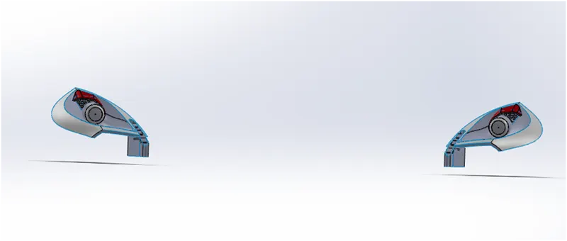
Headlights:
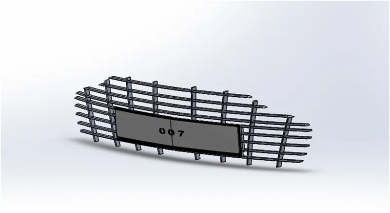
Front grille:
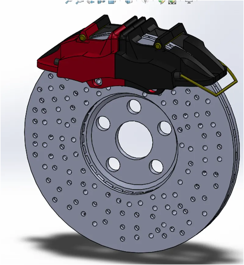
Brake assembely :
The body:

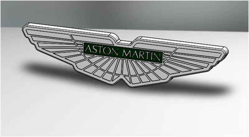
The logo:
The complete assembley: after completing the assembley we need to to use the mate command
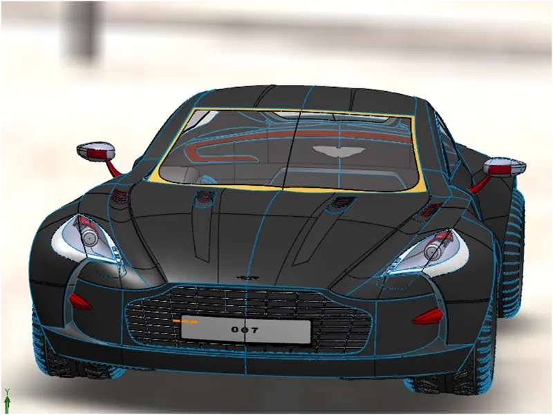
Viewpoint:
Front :
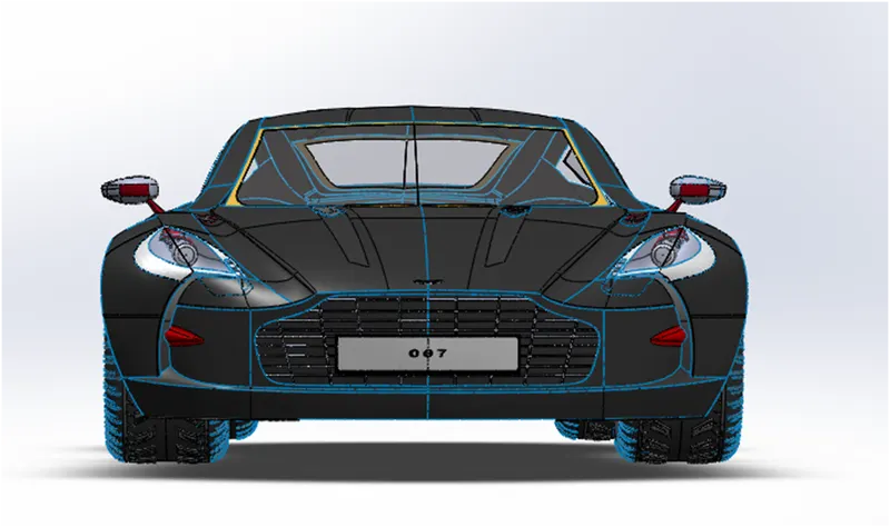
Side:
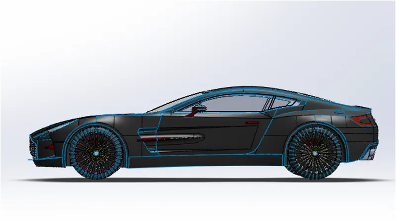
Back:
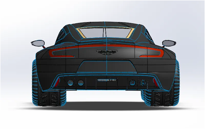
Top :
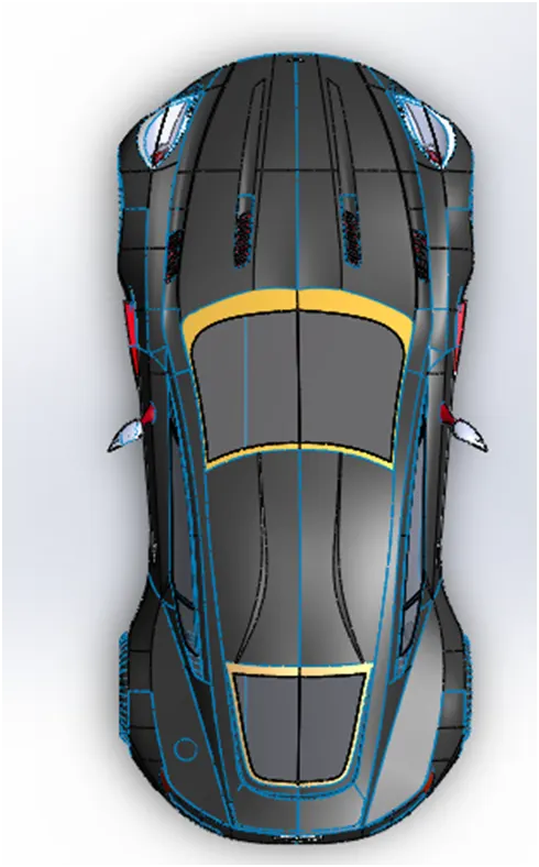
Isometric:
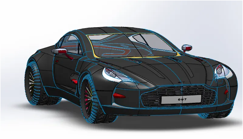
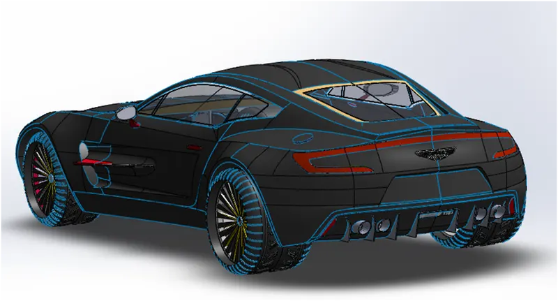
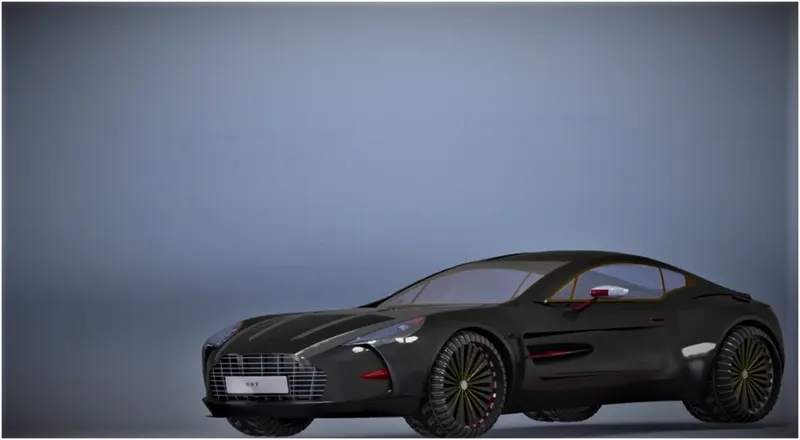
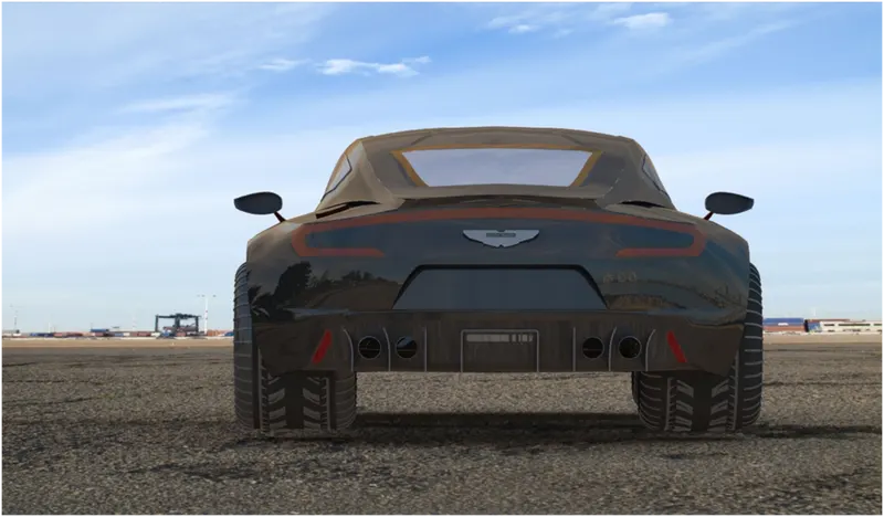
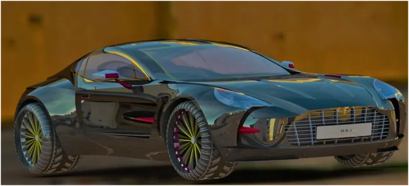
Rendered images :
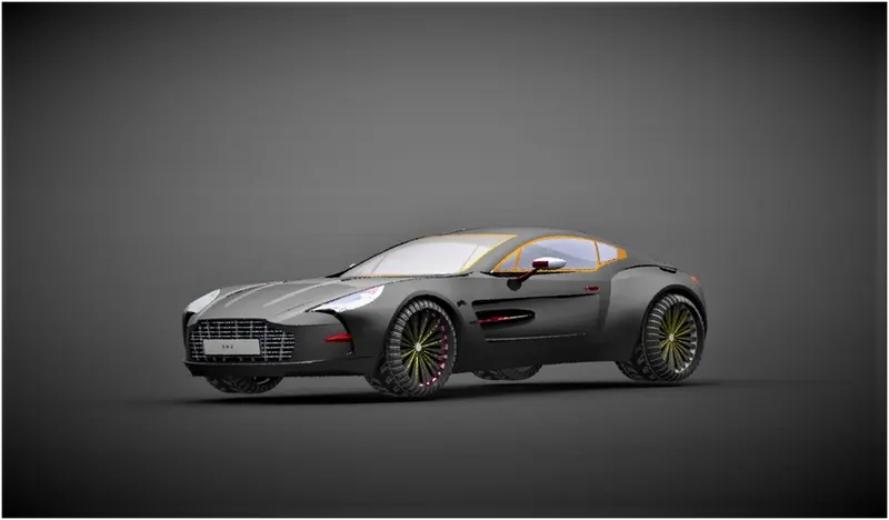

Result :
The complete design of aston martin was completed using solid works