Assignment 7-Side Pole Crash Simulation Challenge
Aim
To do deck setup using HyperMesh and HyperCrash and perform side crash analysis.
Indroduction
A crash test is a form of destructive testing usually performed in order to ensure safe design standards in crashworthiness.
The crash testing requirements can be divided into two
- Regulatory testing: FMVSS, ECE
- Consumers testing: NCAP, IIHS
The regulatory test provide answer to the question, wheather the car passes or fails if the injury recorded in the dummy is less than the standard value then it is said to be passed.
Consumer testing will give star rating based on the injury results. They will also give rating based on the individual components prformance from the car.
Side impact tests, these forms of accidents likelihood of fatality, as car do not have a significant crumple zone to absorb the impact force before an occupant is injured.
Pole impact tests, A difficult test which places a large amount of force on a small proportion on the side of the vehicle.
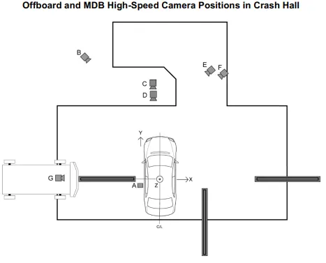
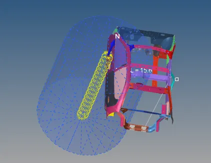
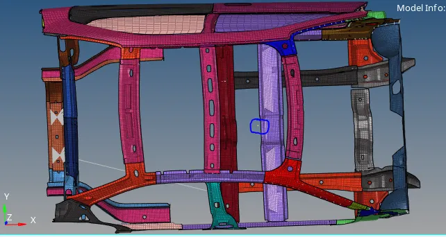
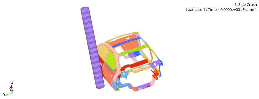
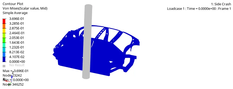
fig:- side crash set up
Objective
Check unit system and either follow [Mg mm s] or [Kg mm ms]
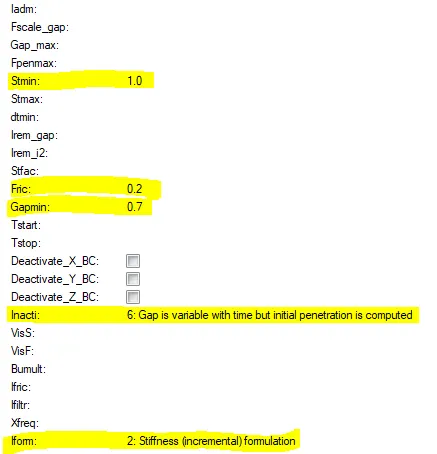
Create appropriate interface, friction 0.2 and recommended parameters
Make sure of no penetrations and intersections
Correct rigid bodies if any issues
Create rigid wall with friction 0.1
Compare the model weight with the full scale 300 k nodes model and use added masses to reach target weight of 700kg while getting CG about the required range
Initial velocity 35 mph
Checker to ensure good quality
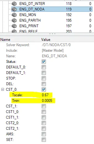
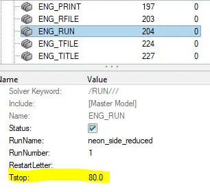
Time step :0.5 to 0.1 microseconds and run time 80 ms
Use model checker to ensure good quality
Output request
Sectional force in the cross member
Intrusion at B_pillar, Hinge pillar and fuel tank region
Peak velocity of the inner node of the door
Procedure
Importing model
The first step is to open the HyperWork software and in the interface it will ask to select the a solver, here we select Radioss as a solver. Then we need to import the model of _0000.rad file as shown below
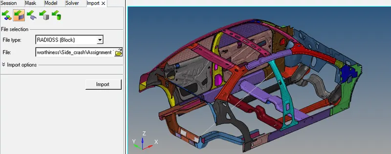
- Check unit system and either follow [Mg mm s] or [Kg mm ms]
For checking unit system go to Model->cards-> BEGIN_CARD as shown below
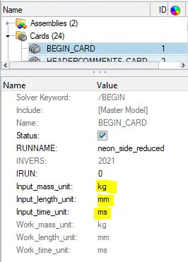
Since the unit followed is [Kg mm ms] we will follow the same unit system throughout the analysis.
- Make sure of no penetrations and intersections
Penetration is defined as the overlap of the material thickness of shell elements whereas Intersection is defined as elements that actually pass completely through one another.
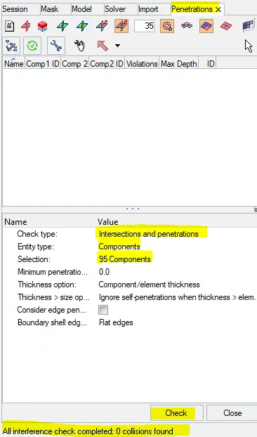
All the models should be checked for penetration and intersections because it will affects the results.
Go to Tools-> penetration checks-> all the components than click on check we can see below there is no any intersections and penetrations.
- Create appropriate interface, friction 0.2 and recommended parameters
Interfaces are defined to model how parts interact when they come into contact with each other.
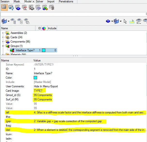
In this case Type 7 interface is defined. TYPE 7 Interface is multi-usage impact interface, modeling contact between a master surface and group of slave nodes.
Go to model browser->groups->create-> select type 7 and enter recommended parameters with friction factor of 0.2
Time step :0.5 to 0.1 microseconds and run time 80 ms
To check these paramter in Hypermesh, we will navigate to Cards under Model browser to check the run time. and enter the value of run time and Tmin as shown below.
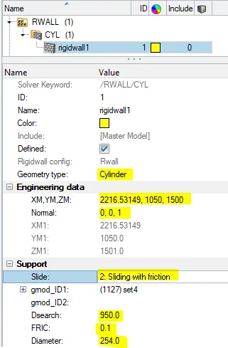
- Create rigid wall with friction 0.1 as per referance model
Rigid wall entities provides a method for treating a contact between a rigid surface and nodel points of a deformable body.
Go to solver model->create->Rwall and select CYL
- Initial velocity
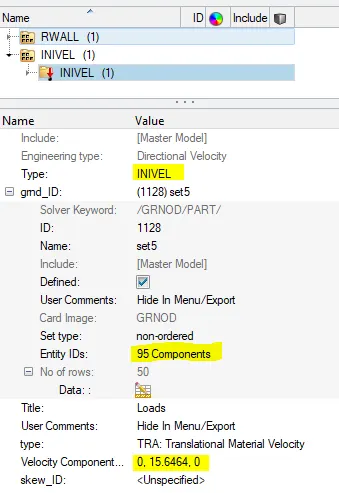
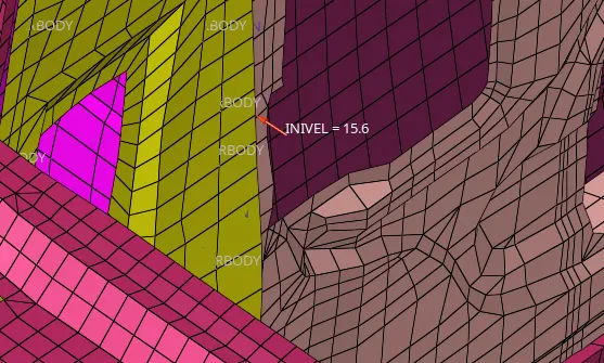
Initial velocity 35 mph or 15.6464 m/s
Solver browser-> create-> boundary condition->INIVEL
Compare the model weight with the full scale 300 k nodes model and use added masses to reach target weight of 700kg while getting CG about the required range
first of all we will check mass and CG of the vehicle in HyperCrash for better visualization.
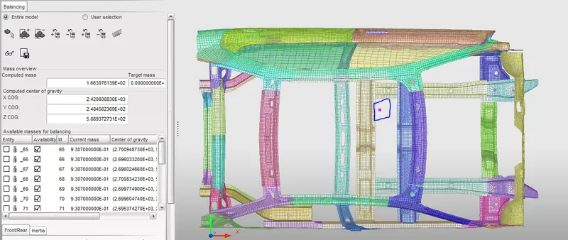
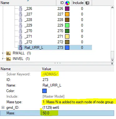
In the above figure, we can see the mass of the vehicle is 166 kg and CG of the vehicle (as shown above). In general, the Cg of the vehicle is somewhere just behind the driver's seat. so in order to get the required CG location , we will be adding mass for getting at required location CG. the total mass of the vehicle is 700kg. In Hypermesh, under solver browser we will right click and navigate to create->ADMAS. In ADMAS panel we will specify the required mass to selected nodes amd mass types as 1 as shown below.
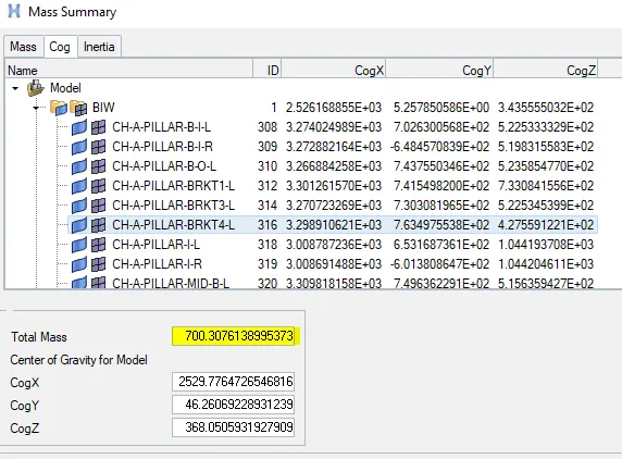
After adding mass at different location of the vehicle. Go to Tool->Mass details-> mass Cog inertia, here we can see total mass of the vehicle and CG of the vehicle.
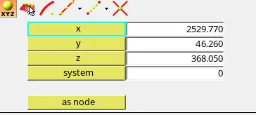
After getting the Cog of the vehicle, go to Geometry->node-> enter the value of CogX,CogY and CogZ than click on create. Now we can see the Cog point of the vehicle a shown below.
Sectional force in the Cross member
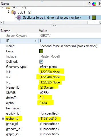
Sectional force tells us how the force are transmitted through a particular section. In our case B-pillar and driver rail. Sectional force are calculated in order to ensure the safety of the passanger.
Go to solver browser->Create->Frame->mov
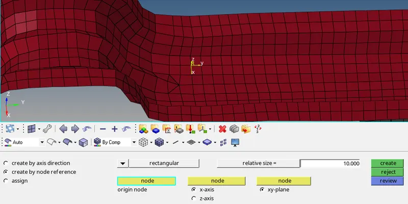
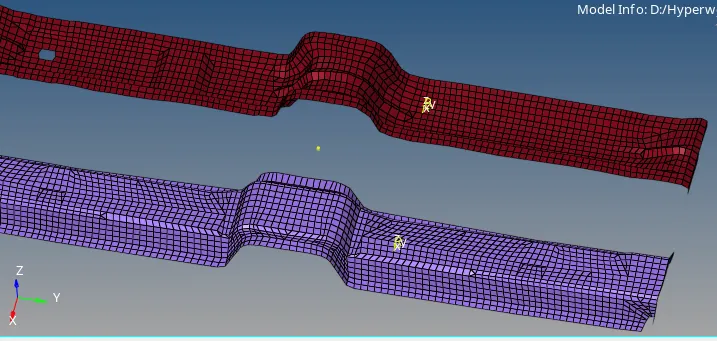
Go to solver browser->Create-> section->SEC
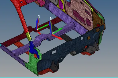
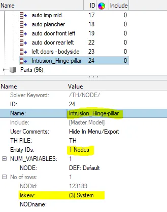
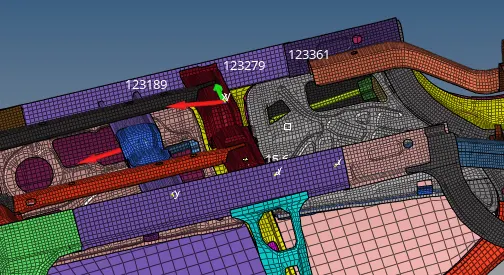
Intrusion at B-pillar, Hinge pillar and fuel tank region
The instrusion is created to know the displacement of velocity of the particular part of the wholw assembly before and after crash.
Go to solver browser->Right click ->create -> skew -> mov than select the node as origin axis and plane.
Go to output block -> right click -> create-> rename it as per required.
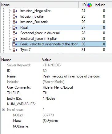
Peak velocity of inner node of the door.
The peak velocity is created at inner door oof the car. To create skew we need skew as reference. create skew
Now got o Model browser-> output block->Right click -> create -> rename to peak velocity of inner node of the door.
Go to TH select skew and specified node.
Model check
To check the qaulity of the model in Hypermesh, In main menu bar we will navigate to Tools->Modelchecker->RadiossBlock, this will open a new model checker browser.
In the browser, we will run the checks command which is top right side. after running the checks, there is no error in the model and only warning are present, warning can be ignored.

Since there is no error in this model and has only warning which can be ignored
Now we can proceed for simulation
Simulation
Go to Analysis ->Radioss than as shown below.

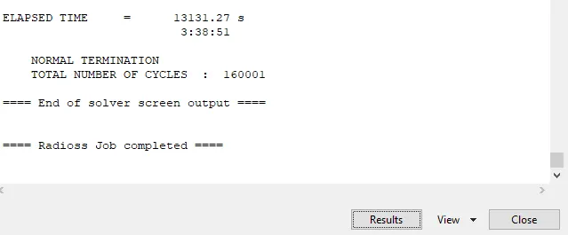
After clicking Radioss we get the solver window as shown below, after few minutes Radioss does the job and click on Result
After Clicking on result it will switch to Hyperview window
Now its time to energy error and mass error check and this is done by analyzing the radioss engine output file. it can be accessed from the same directory as the starter and engine file and it ifile extension by _0001.out open this file in notepad as shown below.
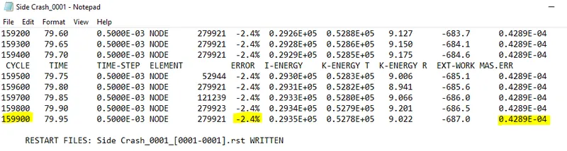
The energy error and mass error is -2.4 % and 0.00428 %. Since the energy error is negive it means some energy has dissipated. Contact energy error can be reduce by decreasing the penetration vaule, penetraction can be removed on the model. Hourglass energy error can be reduce by using fully integrated elements.
The energy and mass error are in acceptable region.
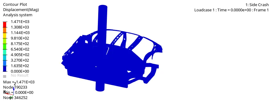
Results
Energy plots:
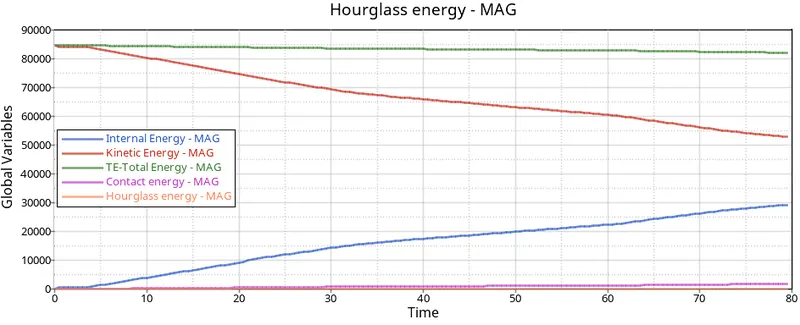
Hourglass energy remains almost zero and we can see contact energy increases towards the end of the simulation due to contact definition coming into action.
Internal energy increases after the impact with the pole, Kinetic Energy decreases as the vehicle comes to a stop after the collision and total energy remains all most constant.
Total energy = IE+KE+HE+CE.
Sectional forces:
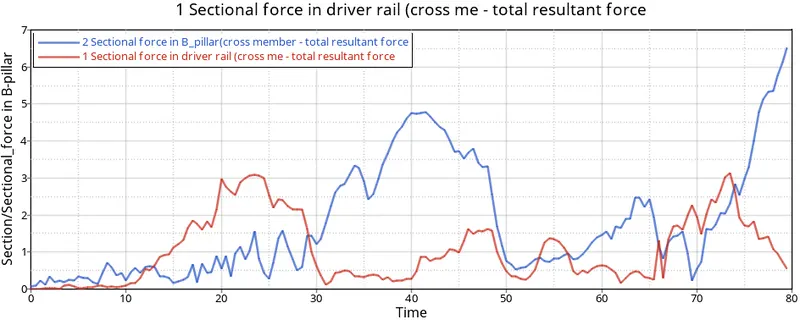
From the graph, total resultant sectional force in the driver rail is having few fluctuation in the result as compare to B_pillar cross member.
Moreover, B_pillar has peak at around 40 ms whereas in near driver rail it is around 20 ms.
Intrusion
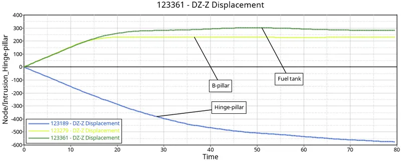
From graph, we can saw that the maximum amount of intrusion was found to be in the Fuel tank followed by the B_pillar and Hinge-pillar has minimum amount of intrusion. In Fuel tank there was no cross member that can reduce the amount of displacement, it is one of the reason for more intrusion on it.
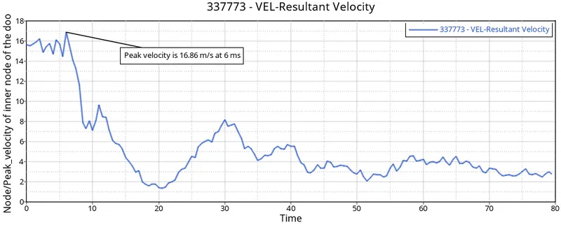
The peak velocity for the inner side door hits its peak value of 16.86 m/s at 6 ms that is when the impact actually happens after that velocity decreases rapidly and goes on fluatuating.
Rigid wall force
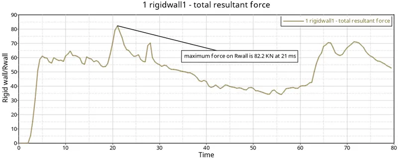
We can see some gap at starting, after this time car is impacting on the rigid wall with huge inertia and rigid wall increases around 60 KN in a short span of time and its goes on fluatuating at reaches maximum at 82.2 KN at 21 ms.
Learning outcomes
Able to
- Creating different rigid wall
- Important of Interface
- Kinematic condition
- Different load case defination
- Debugging and and time steps
- How to speed up computation
- Different type of output request
Conclusion
from the side crash analysis we came to know, Some stiffness should be increased near fuel tank in order to reduce intrusion
Force is distributed along the metalic pillar and other member and intrusion at various point is determined. for preventing injury to the passanger in the car some Airbag and seat belt is recommended.