Assignment 7-Side Pole Crash Simulation Challenge
Obejective: To perform side pole crash analysis on the Neon model
- Check unit system and either follow [Mg mm s] or [Kg mm ms].
- Create appropriate interface ,friction 0.2 and recommended parameters.
- Make sure of no penetration and intersections.
- Create rigid wall with friction 0.1 as per referance model.
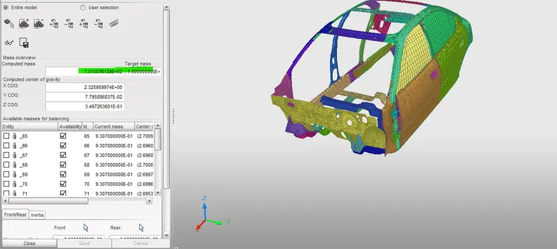
- Compare the model weight with the referance model and use added masses to reach target weight 700kg while getting CG about the required range.
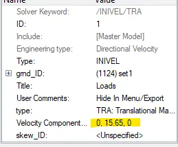
- Initial velocity as shown in picture.
- Use model checker to ensure good quality.
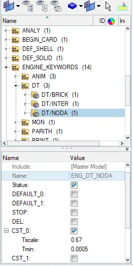
- Timestep :0.5 to 0.1 microseconds.
- Run 80ms.
Output requests:
- Sectional force in the cross member.
- Intrusion at B pillar,hinge pillar and fuel tank region.Provide recommendation on what can help to reduce Fuel tank intrusion.
- Peak velocity of inner node of the door.
Procedure:
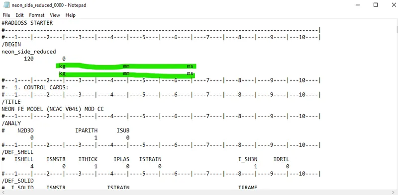
1.The unit system was checked for the simulation from the engine file and was found to be Kg mm ms hence no changes were made
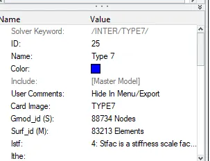
2. Then after this type 7 Interface was created using friction 0.2 and other recomended parameters
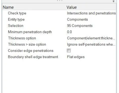
3.After this penetration checks were performed through model checker tab and no intersections were found
4 Rigid wall was to be made for the simulation hence through the solver tab-->create-->RWALL(cyl) was created of Dia 254 mm
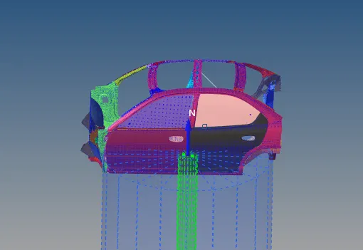
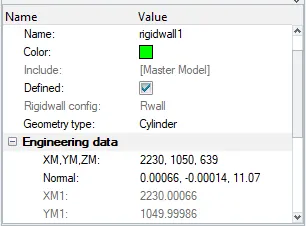
The normal was selected using the nodes on the nodes on the outer surface of the door
5.The initial weight was found to be 166 kg hence for the COG adjustment the Mass was added to the Vehicle body including the passenger,fuel tank and Gear box
6.Initial velocity was to be assigned to the vehicle for Inivel through the BC's-->Sover tab--> Inivel was assigned to the model
The velocity was assigned along X axis
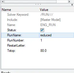
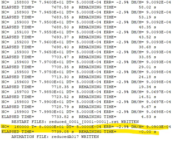
7.Finally the time step and run time was assigned to the simulation which is shown in below fig
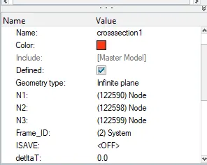
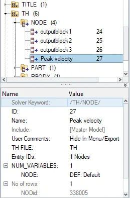
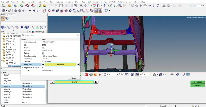
8.Output Request for the model were to be created hence Cross section were created along the two pillars and Similarly the Intrusion was checked along the B pillar hecne for this three random nodes were selceted on the B pillar and for the Peak velocity of inner node of the door the node was selected at the inner side of the door
After this output request were created for the same
9.Then after this the simulation was run through the analysis-->Radios--> through HM window
and energy error was found to be acceptable
10. The Forces along the cross section
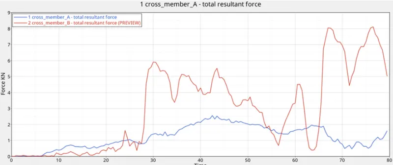
From the above graph we can conclude that cross member A experiences more force than the member B,because it is inline with the Pole
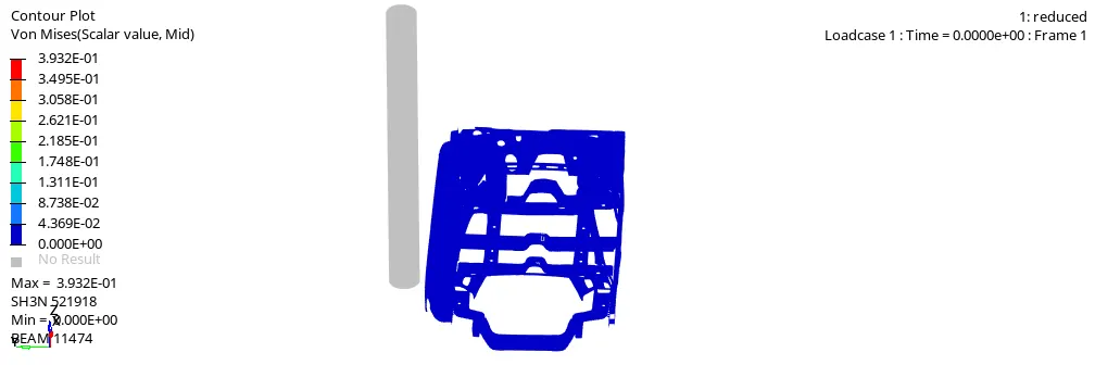
11.The Von misses stress are checked through the AnimatedH3D file, the Max stress acheived during the cycle is 3.932 Mpa
12. Intrusion along the 3 Nodes
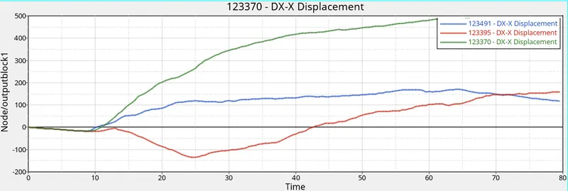
The 3 Nodes on the section near the fuel tank,B pillar were selected and the results can be checked from the above graph
The green node (Fuel Tank)experiences the higher displacemnt 484 mm and the other 2 nodes faces about 128 mm of displacment
and the negative displacment tells us that intrsuion has increased after crash
For improving the Intrusion we can introduce a reinforcemnt along the fuel tank
13.The Peak Velocity at the inner node of the door
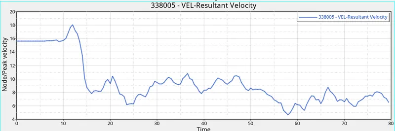
The peak velocity is found 15.84 mm/ms during the start of the simulation and reduces with end of simulation,which means that it has better resistancer to force
Conclusion: Hence from the above simulation and the time history files we can conclude that Cross members A and B are playing vital role in the simulation and even the door material ,so designing them with better parameters results in better Customer safety