Assignment 7-Side Pole Crash Simulation Challenge
Aim: To perform a side of a car at 35mph in radioss. using the following boundary conditions.
Objective:
Boundary Conditions:
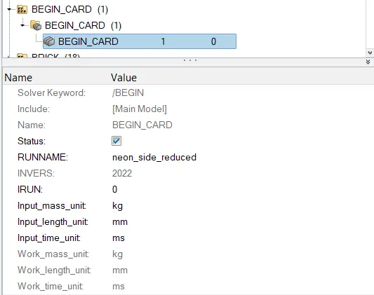
- Check unit system and either follow [Mg mm s] or [Kg mm ms].
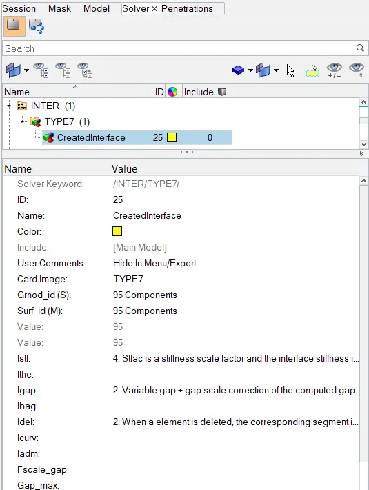
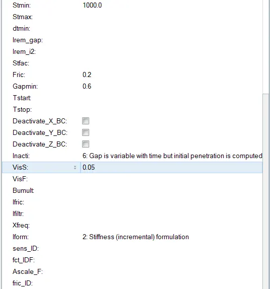
- Create an appropriate interface, friction 0.2, and recommended parameters.
- Make sure of no penetration and intersections.
- Create a rigid wall with friction 0.1 as per the reference model.
- Compare the model weight with the reference model and use added masses to reach the target weight of 700kg while getting CG about the required range.
- Initial velocity - 20mph, as per the standards.
- Use model checker to ensure good quality.
- Timestep: 0.5 to 0.1 microseconds.
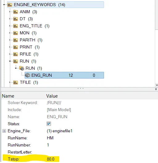
- Run 80ms.
To plot
- Sectional force in the cross member.
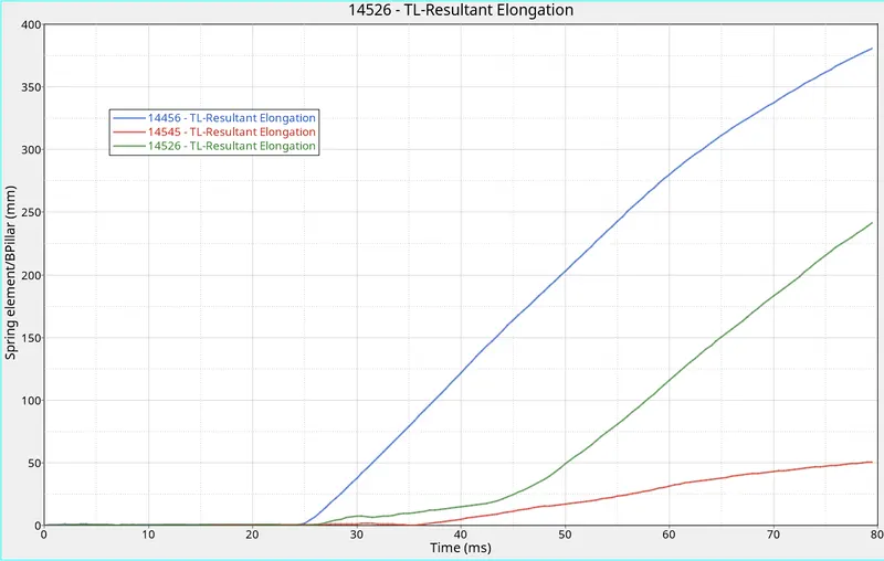
- Intrusion at B pillar,hinge pillar and fuel tank region. Provide recommendations on what can help to reduce Fuel tank intrusion.
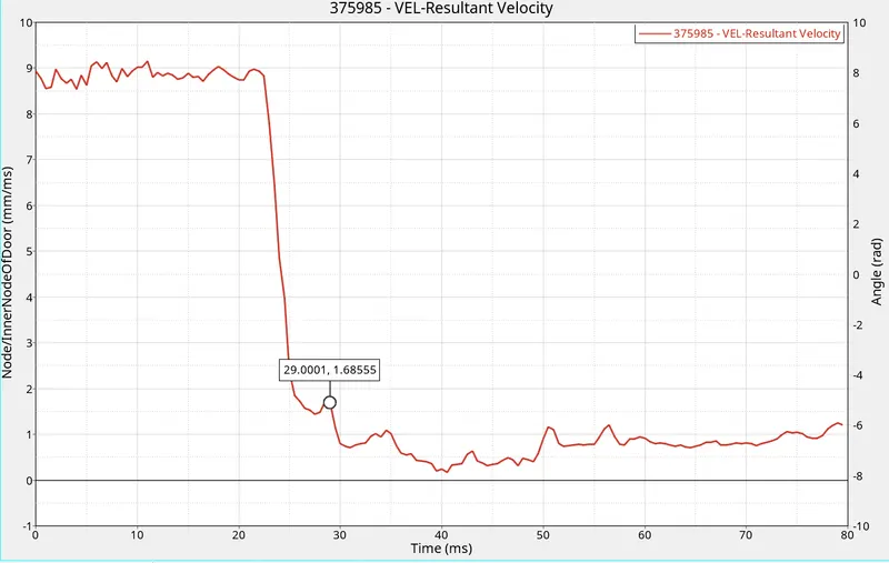
- Peak velocity of an inner node of the door.
Introduction: (Reference: Ncap)
As you get in the median, a car from another direction comes out of nowhere and hits your car right on the driver’s side. This type of collision is known as a side-impact or T-bone accident.
Some side impacts involve a vehicle travelling sideways into rigid roadside objects such as trees or poles. Often this is the result of a loss of control on the part of the driver, owing to speeding, misjudgement of a corner or because of a skid in slippery conditions. Such accidents are severe and the frequency of death or serious injury is high.
In Euro NCAP’s test, a car is propelled sideways at 32 km/h against a rigid, narrow pole. The car is placed at right angles to the direction of motion, or as is done from 2015 onwards, at a small angle away from the perpendicular. Where a vehicle is equipped with a centre airbag to protect against the front seat occupants hitting each other, two average male side impact dummies are placed in the front seats. Where there is no centre airbag, single dummy is placed on the driver’s seat.
This is a very severe test of a car’s ability to protect the driver’s head. As the loading on the car is so localised, deformation can be very high and the pole can penetrate deeply into the passenger compartment. Without effective protection, the pole would strike the head resulting in serious injuries. Head protection airbags – often curtain airbags mounted above the side windows but sometimes seat-mounted thorax/head airbags – have become a common solution but great care is needed to ensure effective performance of such devices.
Procedure:
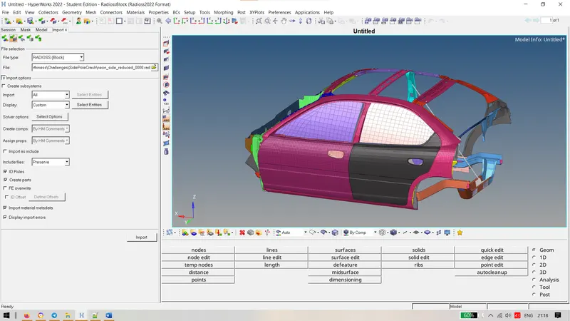
- Import the given .rad file into hypermesh.
- Check for the begin card for the units in the solver browser.
- Create a type 7 interface with friction as 0.2 using the following conditions:
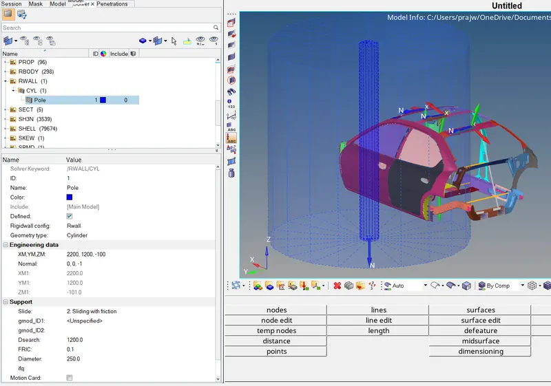
- To create a rigid wall with a friction of 0.1 by Create > Rwall > Cylindrical > Following Conditions. Select a node at the car window and set the xm, ym, zm by selecing a node and add a normal reaction to the cylinder as -1 in z axis.
- To make sure there are no penetrations and intersection in the component by Tools > Penetration Check
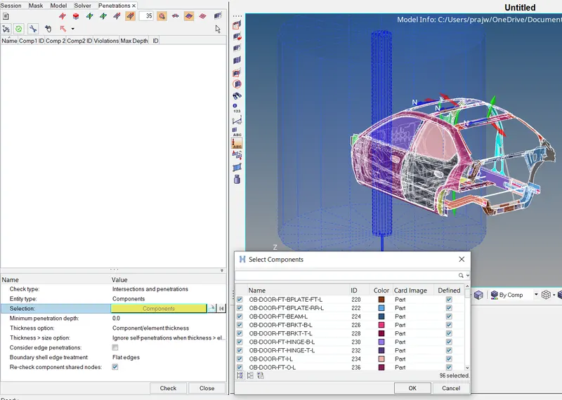
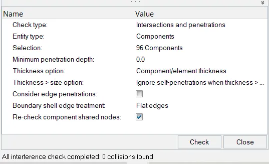
- Compare the model weight with the reference model and use added masses to reach the target weight of 700kg while getting CG about the required range.
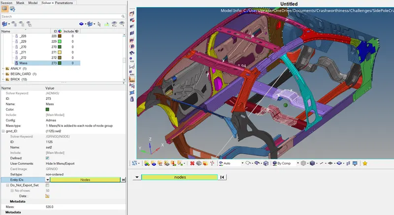
- To compare the model weight and use added masses to reach target weight 700kg while getting CG about the required range at the center. The given model was less in mass with 166 kg. We check by using Tools > Mass Details > Mass, cog and inertia and check the mass.
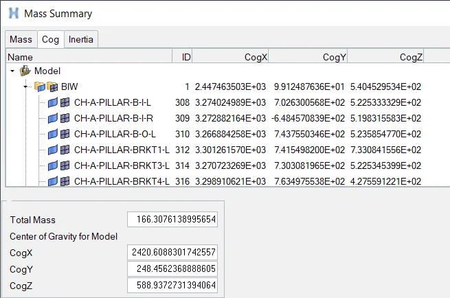
We create a node using the above x, y and z coordinates and then create a admas (534 kg) > using settings with the following set of nodes.
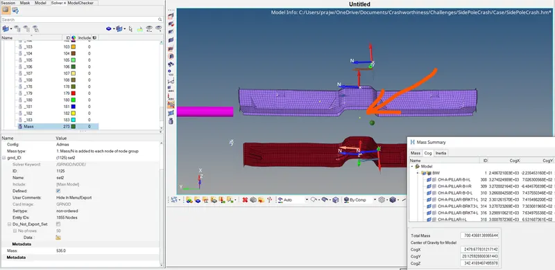
Final cog obtained is at the shown node at location with red arrow marker
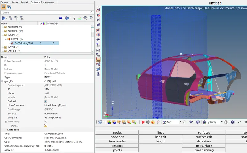
- To create an initial velocity of 20 mph in y direction for all the components. (20mph = 8.94mm/ms)
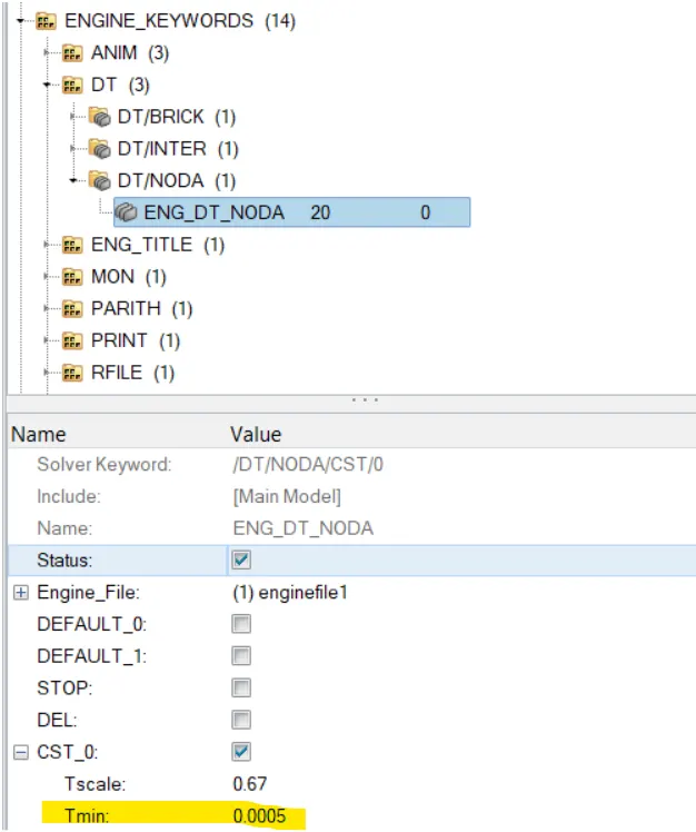
- We set a time step for 0.5 microsecond (0.0005ms) and run for 80 ms.
- Now lets create moving frames for recording forces in the section (Frames/Mov - Describes moving frames. Relative motion with respect to a reference frame).
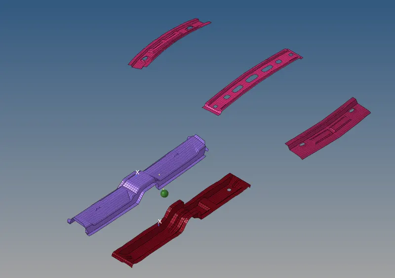
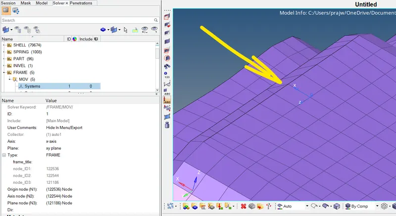
We first hide all the components and work on the rail by pressing D > selecting frame > reverse. For sectional forces in the members we create a node at the given location and select 3 nodes by using the right hand thumb rule where the thumb points the direction in which the sectional force is to be calculated.

Following mov frame is created:
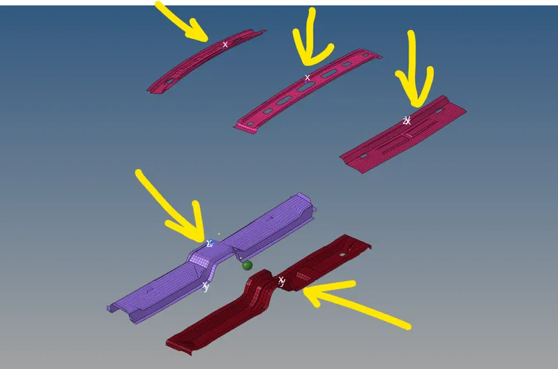
Similarily we create the mov frames on all the five cross members.
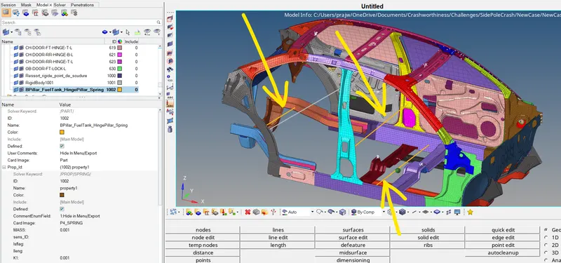
- For intrusion at B pillar, hinge pillar and fuel tank regions we create 2d springs for the displacement at the following places:
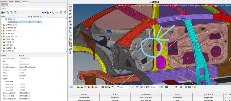
- Now to calculate the peak velocity on the inner node of the door, we will be creating a node at the inner side of the door using mov skew frame by using same right hand thumb rule.
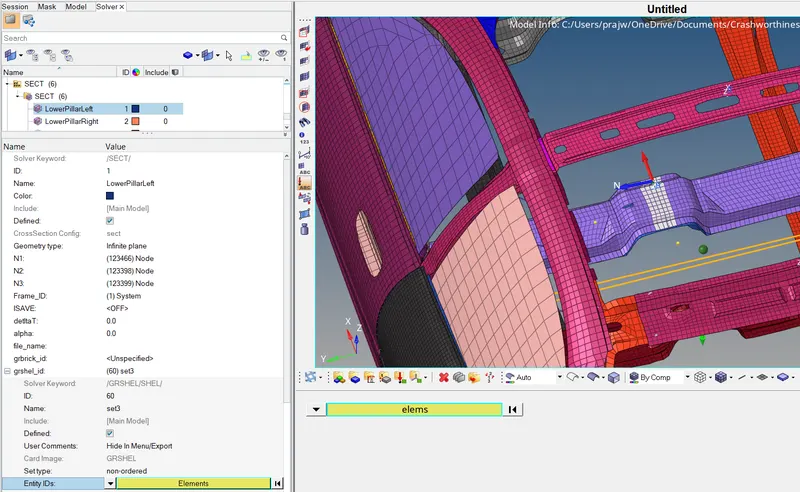
- For sectional forces in cross members, we create sections by Sect > select the elements which are in the cross section as shown:
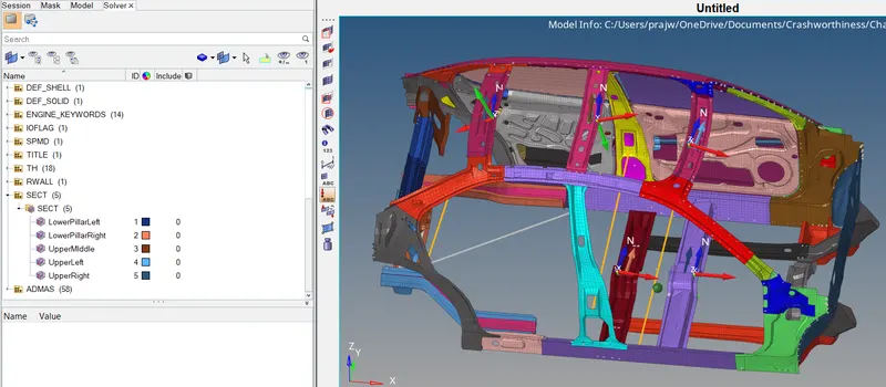
Similarily we create sections for all the members:
OUTPUT BLOCKS
- Now, after creating all the bcs for required forces, we now create time history file for recording the forces by create > TH > node and select the above skew created as system id as 6.
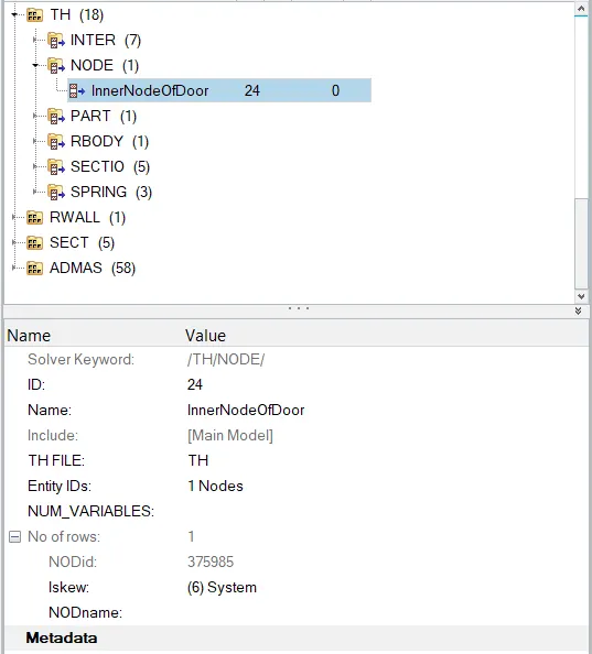
- For the three springs by creating TH > Springs > SelectSpringElement.
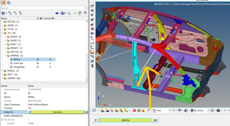
We also create for the other springs: 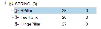
- After creating all the TH files for all the outputs requested; following is obtained:
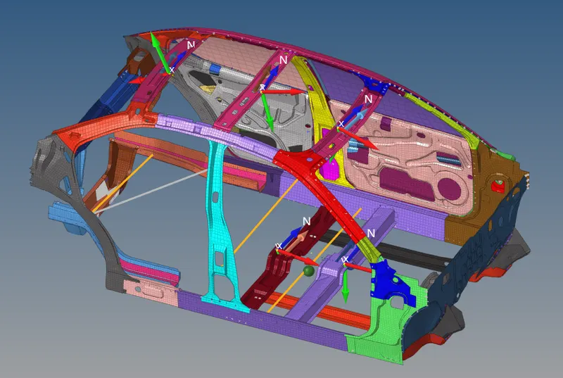
- At last we check for any errors by Tools > Model Checker > Radioss Block > Run and then run the simulation by analysis > radioss > radioss and obtain the following Results.
Results:
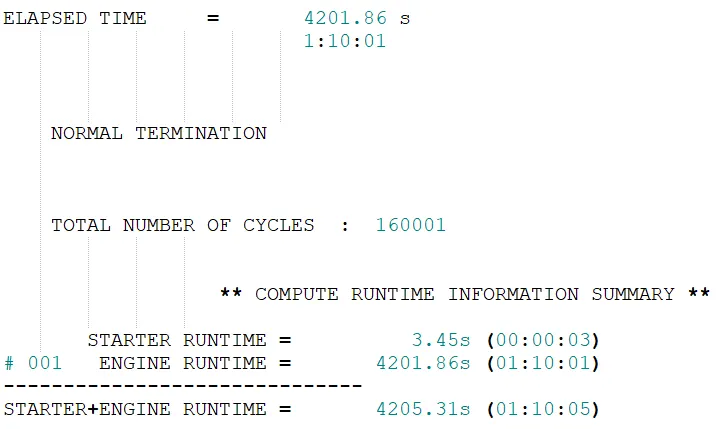
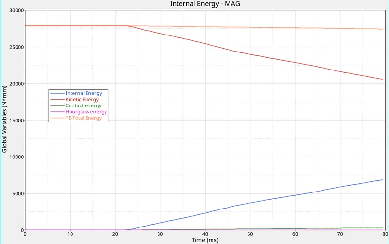
Elapsed time is 1hr 10mins with energy error as -1.3%, 6916 J as internal energy, 0.2050e5 J as total kinetic energy and 0.7482e-4 as mass error.

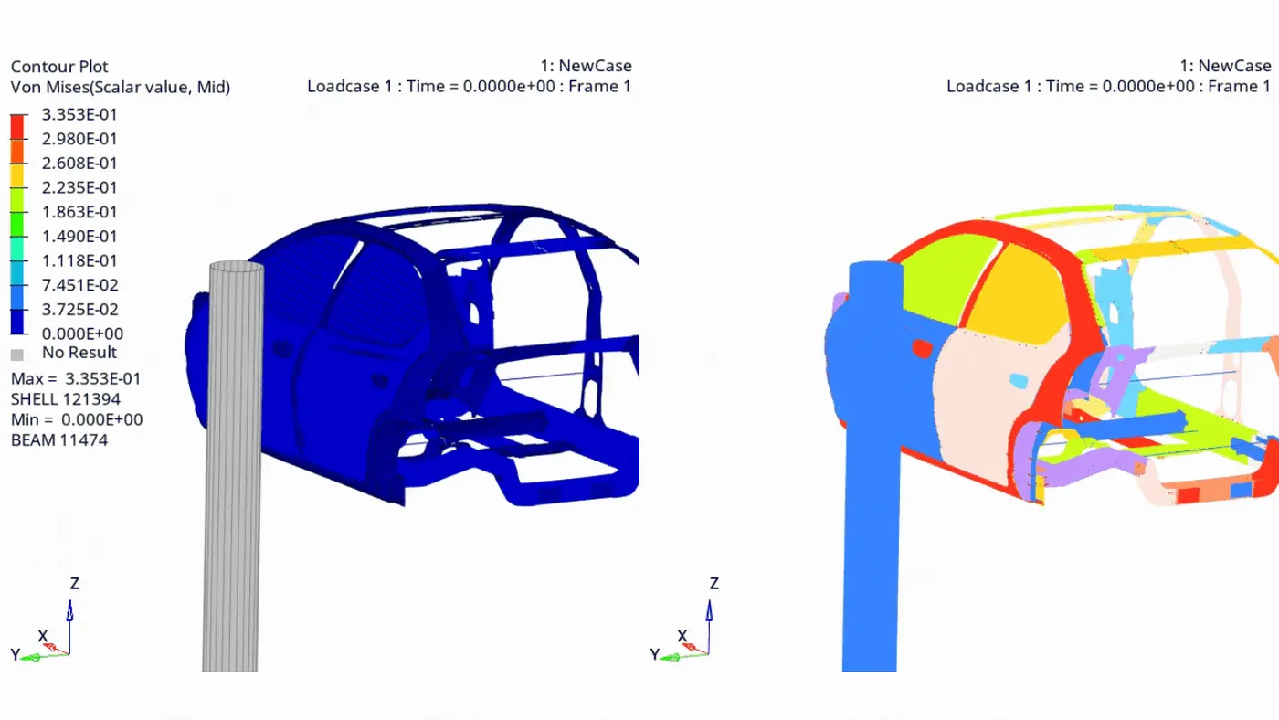
Max stress of 335Mpa is observed.
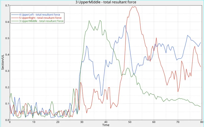
After 26ms, most of the cross sectional forces are observed to be increasing.
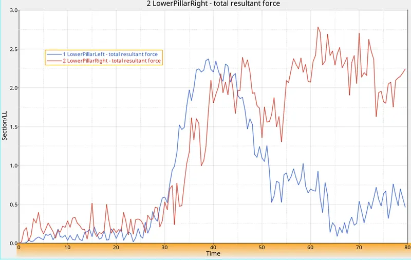
Sectional forces in the members are shown below where maximum force is observed in the upper right member with a maximum force of 690N. In the lower members, the maximum force is to be similar upto 47ms but the maximum resultant force is observed to be in lower member with 2760N which is increasing after 54ms.
For peak velocity for the inner node of the door, we can see that node is stable and maintaining the initial velocity of the car untill it crashes into the pole. After the crash has taken place or after the vehicle door has just hit the pole there is a sharp decrease in the velocity of the node. So, after the crash has taken place the maximum or peak velocity seen is 1.685 mm/ms or 3.7mph.
For intrusions of b pillar, fuel tank and hinge pillar following displacements or elongations are recorded: Lowest amount of deflection is observed in the fuel tank region with maximum of around 51mm and for b pillar it was 380mm and also for hinge pillar it is around 240mm. The b pillar is experiencing maximum deflection because the pole is crashing into the b pillar.
Conclusion: The simulation of a side impact has been successfully done with the given boundary conditions and following energy plot for internal energy, kinetic energy, contact energy, hourglass and total energy. The hourglass energy is less than the internal energy which is great. When the side impact simulation starts the internal energy and kinetic energy are constant and after 23 secs i.e. when the car crashes into the pole the kinetic energy reduces because the kinetic energy depends on the square of the car velocity. The internal energy is also seen to be increasing because during impact a lot of energy is generated when the elements are crushed. Due to this total energy seems to be constant. Very slight increase in the contact energy is also observed.
The fuel tank intrusion can be reduced by adding cross members between the fuel tank rails by making it more stiffer so that the deformation/elongation of the member reduces. They may also have reinforced side beams. For human safety side airbags should be installed so that they deploy on impact.