Assignment 7-Side Pole Crash Simulation Challenge
AIM:
To perform a side pole crash simulation with the BIW frame in RADIOSS and requests for outputs as mentioned above.
OBJECTIVE:
1.To Check unit system and either follow [Mg mm s] or [Kg mm ms].
2.To Create an appropriate interface, friction 0.2, and recommended parameters.
3.To Make sure of no penetration and intersections.
4.To Create a rigid wall with friction 0.1 as per the reference model.
5.To Compare the model weight with the reference model and use added masses to reach the target weight of 700kg while getting CG about the required range.
6.To Initial velocity - 20mph, as per the standards.
7.To Use model checker to ensure good quality.
8.To Timestep :0.5 to 0.1 microseconds.
9.To Run 80ms
OUTPUT REQUESTS:
1.Sectional force in the cross member.
2.Intrusion at B pillar,hinge pillar and fuel tank region. Provide recommendations on what can help to reduce Fuel tank intrusion.
3.Peak velocity of an inner node of the door.
THEORY:
The slide crash analysis is important for the coocupant as well as passenger saftey. If the holding structure is not good all the impact force may travel into the main compartment and this leads to injured the occupant.
Crash analysis is an integral part of saftey analysis and is often completed at intersections and corridors. The crash analysis can help assess concerns and help determine potential improvement options.
A crash test is a form of destructive testing ususllly performed in order to ensure safe design standards.
NEW CAR ASSESSMENT PROGRAM(NCAP):
It is a goverment car saftey program tasked with evaluating new automobile designs for performance against various saftey threats.
Standard crash test performed by NCAP are,
1.Frontal offset testing (64 km/h proposed)
2.Side_Impact testing.
3.Pedestrain Impact testing.
4.Rear Impact testing.
5.Child dummy dynamic crash testing.
FEDERAL MOTOR VEHICLE SAFTEY STANDARDS(FMVSS):
FMVSS are US federal vehicle regualtions specifying design, construction, performance and durability requirements for motor vehicles and regulated automobile saftey related components, systems and design features.
They are the US counterpart to the UN regulations developed by the World Forum for Harmonization of Vehicle regualtions and recognized to a varying degree by most countries except the US.
BODY IN WHITE(BIW):
BIW is the stage in automobile manufacturing in which a car body's frame has been joined together that is before painting and before the motor, chassis sub-assemblies, have been integrated into the structure.
Assembly involves different techniques such as Welding, Riveting, Clinching, Bonding and Laser Brazing.
PROCEDURE:
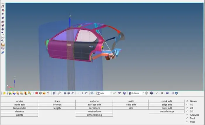
1.Import the file.
CASE-1 (Check unit system and either follow[Mg mm s] or [Kg mm ms]):
1.Goto model browser > Cards > Begin Card > Check for the units.
2.The unit system followed in Kg-mm-ms.
CASE-2 (Create appropriate interface ,friction 0.2 and recommended parameters):
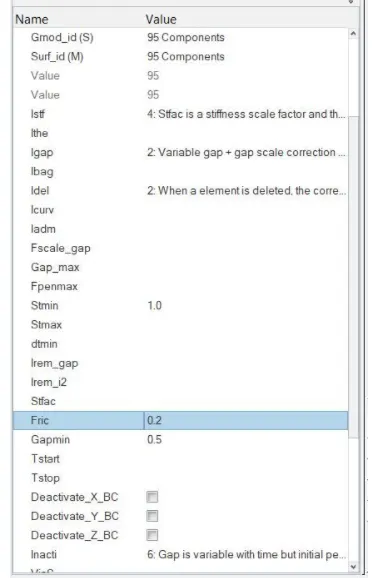
1.Type 7 contact is used with all recommended properties and with friction value of 0.2.
2.For Slave and Master all 95 components is selected.
CASE-3 (Make sure of no penetrations and intersection):
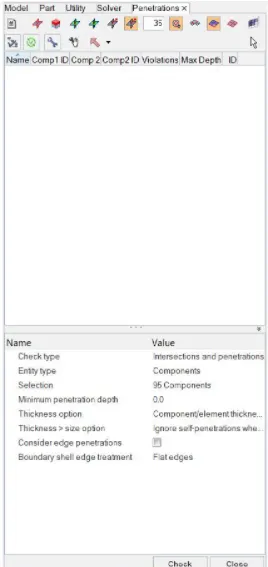
1.Goto Tools > Penetration Check > Select check types as intersections and Penetrions > Select all components > Check.
2.The output result is : All interface check is completed:0 collisions found.
CASE-4 (Correct rigid bodies if any issues):
1.As there is no penetrations and intersecions there is no isses with rigid bodies.
CASE-5 (Create rigid wall with friction 0.1):
1.Goto Solver Deck > Right click > Rwall > plane.
2.Select any node on the bumper and change the x-coordinate such that a gap is maintained.
3.Say that the sliding friction with value of 0.1.
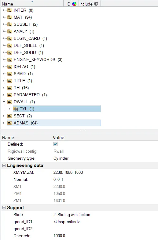
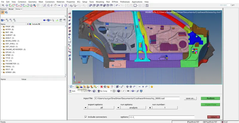
The model with rigid wall is shown below:
CASE -6 (Compare the model weight with the full scale 300k nodes model and use added masses to reach target weight 700kg while getting CG about the required range):
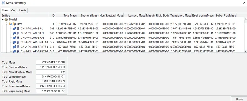
1.Check the mass and COG point.
2.Goto Tools > Mass Details > Mass,COG and Inertia.
3.Intial mass is 180kgs and cog point is not desirable.
4.Add mass to get 700 kgs and desirable COG point.
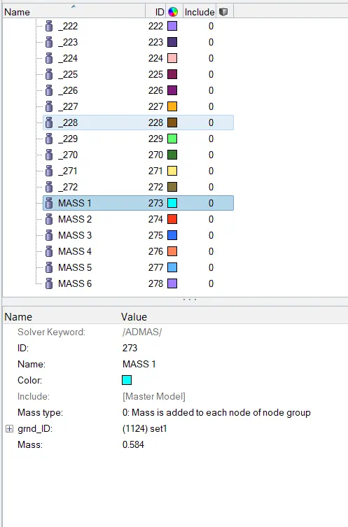
5.Goto Solverdeck > Right click > ADMAS > Select the nodes on which the mass should act > provide value of mass.
CASE-7 (Initial velocity 35 mph):
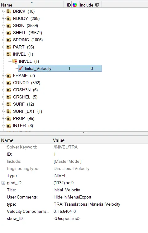
1. Goto Solverdeck > Right click > Create Inivel > Select all components and provide the value of velocity.
CASE-8 (Time-step :0.5 to 0.1 microseconds):
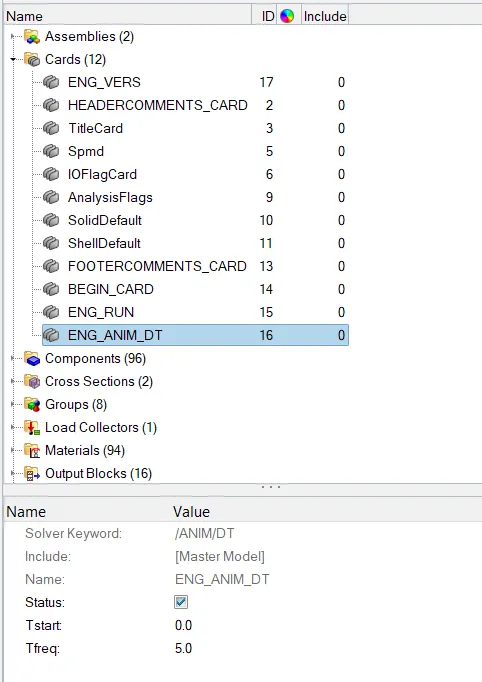
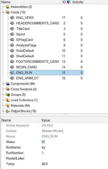
1.Goto Model Browser > Cards > Anim_Dt > Tfreq = 5.
CASE-9 (Run 80 ms):
1.Goto Model browser > Cards > Eng_Run > Tstop = 80.
OUTPUT REQUESTS:
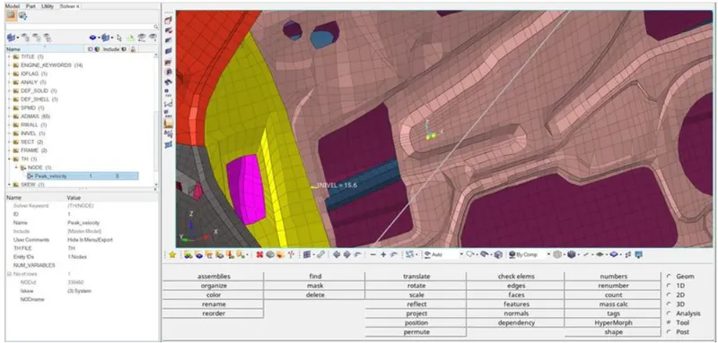
CASE-1 ( PESK VELOCITY OF INNER NODE OF DOOR):
1.We will create a moving frame at the node location by using the same procedure as we used in cross section creation.
2.Then we will create a output block for the peak velocity by specifying the node and the frame or skew based on which the peak velocity is calculated.
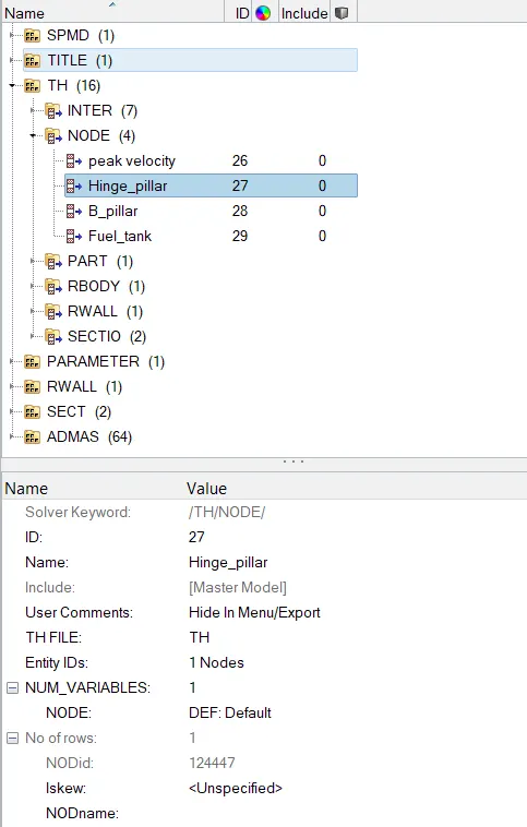
CASE-2(INTRUSION AT B-PILLAR, HINGE PILLAR AND FUEL TANK):
1.Create moving frames at the oppostie side which are at the right B-Pillar, Hinge Pillar and Fuel tank.
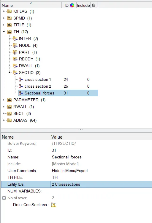
CASE-3(SECTIONAL FORCES IN CROSS MEMBERS):
1.Goto Output Blocks under model browser.
2.Then we will right click and create a new output block.
3.We will select the cross section which we created and thus we will be able to plot graphs to the cross sectional forces in Hypergraph.
SIMULATION:
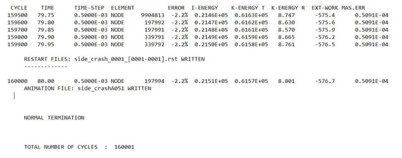
1.The energy error is -2.2% which is acceptable limit. The mass error is 0.05091% which is less than 5% is acceptable.
OUTPUT:
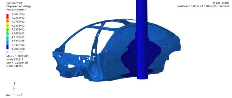
1.We can see the vehicle body is impacting on a Pole. The frame of the vehicle deforms and the vehicle body gets contracted around the pole with left B-Pillar as the pivot point.
GRAPHS:
1.TOTAL ENERGY OF THE SYSTEM:
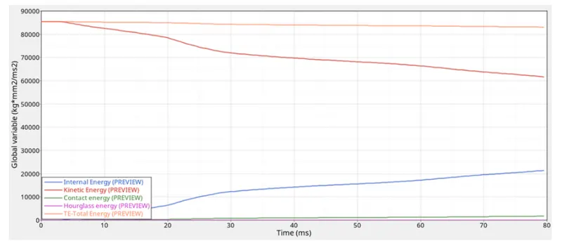
1.There is a high amount of kinetic energy at the start of the simulation but the simulation progress the kinetic energy in the vehicle is decreases and gets converted into internal energy.
2.The total energy in the system is almost constant at 85000 kg*mm^2/ms^2 and due to some energy loss which we can see in energy error there is some decrease in total energy.
2.SECTIONAL FORCES ACTING IN CROSS MEMBERS:
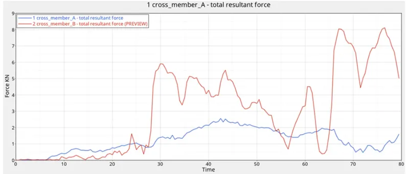
1.We can see that the total resultant force in the rear cross member is more than the cross-member (A). The cross-member(B) is in line with the pole will experience more force.
3.INTRUSION:
I.INTRSUION AT HINGE PILLAR:
1.The final displacement at Hinge Pillar region is 1542.62 mm and the inital distance of fuel tank from frame of reference is 1310.62.
2.Total intrusion is -232.00mm.
3.Thus the total intrusion at hinge pillar region is 232mm but the minus sign indicates that the intrusion is increased after the crash.
II.INTRUSION AT B-PILLAR:
1.The final displacement at B-Pillar region is 1577.71 mm and the inital distance of fuel tank from frame of reference is 1319.49.
2.Total intrusion is -258.42mm.
3.Thus the total intrusion at B-pillar region is 258.42mm but the minus sign indicates that the intrusion is increased after the crash.
III.INTRUSION AT FUEL TANK:
1.The final displacement at Fuel tank region is 1462.71 mm and the inital distance of fuel tank from frame of reference is 1320.00.
2.Total intrusion is -142.42mm.
3.Thus the total intrusion at B-pillar region is 142.42mm but the minus sign indicates that the intrusion is increased after the crash.
4.The increase of intrusion can lead to failure of fuel tank and fuel may drop out of the tank.
5.To prevent the failure we need to reduce the intrusion which we can achieve by adding another cross member in fuel tank region which absorbs some energy and resists the movement of fuel tank region and also the cross member can take deformation.
6.We can increase the strength of the support element near the fuel tank region by changing the material or adding a small support bracket over that region.

4.PEAK VELOCITY OF INNER NODE OF DOOR:
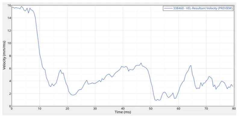
1.The peak velocity measure at the inner door point is 15.94mm/ms till 8ms. After that the speed is starting to reduce to a great extent.
OBSERVATION:
1.Thus the set up of a Side pole crash test is performed.
2.Thus the create of a rigid wall, sectional forces is performed.
3.Thus the forces are distributed during the Side pole crash is performed.
4.Thus the Check energy, mass and momentum balance is performed.
RESULT:
1.Thus the graphical results were plotted for all test cases.
2.Thus the simulation it is observed sucessfully.