Side Crash Analysis Simulation on the BIW Component
AIM: To Perform the Side Crash Analysis on the BIW Component with required Output Requests.
OBJECTIVES:
- Check unit system and either follow [Mg mm s] or [Kg mm ms].
- Create an appropriate interface, friction 0.2 and recommended parameters.
- Make sure of no penetration and intersections.
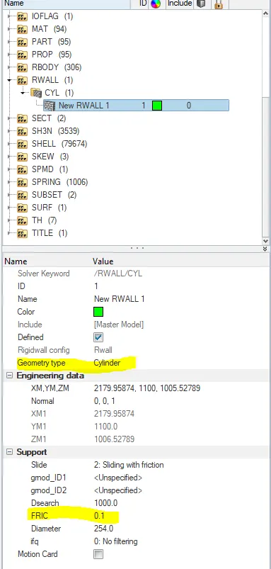
- Create a rigid wall with friction 0.1 as per reference model.
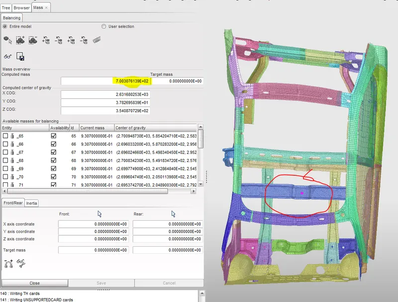
- Compare the model weight with the reference model and use added masses to reach target weight 700kg while getting CG about the required range.
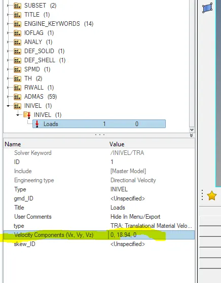
- Initial velocity as shown in the picture.
- Use model checker to ensure good quality.
- Timestep :0.5 to 0.1 microseconds.
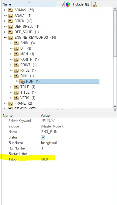
- Run 80ms.
Output requests:
- Sectional force in the cross member.
- The intrusion at B pillar, hinge pillar and fuel tank region. Provide recommendation on what can help to reduce Fuel tank intrusion.
- Peak velocity of an inner node of the door.
PROCEDURE:
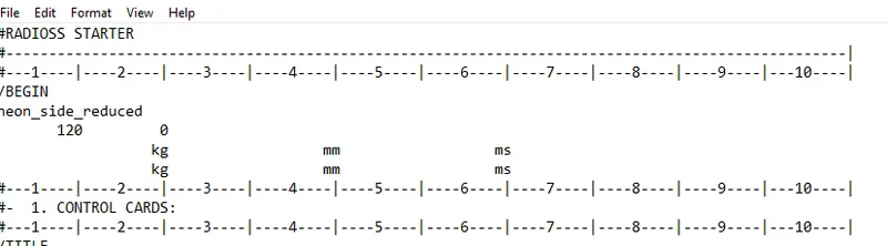
1.Check unit system and either follow [Mg mm s] or [Kg mm ms].
- For that go to the starter file then check the unit system it is [kg mm ms] as shown in below image.
2.Create an appropriate interface, friction 0.2 and recommended parameters.
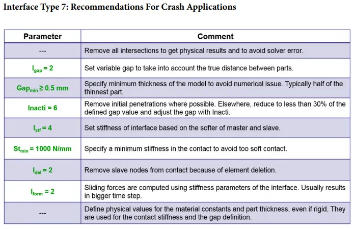
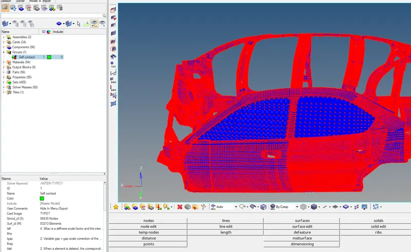
- Here we are creating the type7 interface for the self contact for that we should given all nodes as master and slaves with friction(0.2) and recommended parameters as shown in the below images.
- For that first, we have to create >groups as shown below.
Recommended parameters:
3.Make sure of no penetration and intersections.
- For that go to the Tools>peneterations check>select the which group you want to check as shown in the below images.
- Then click on the check it will show command in the down of the dialogue box.
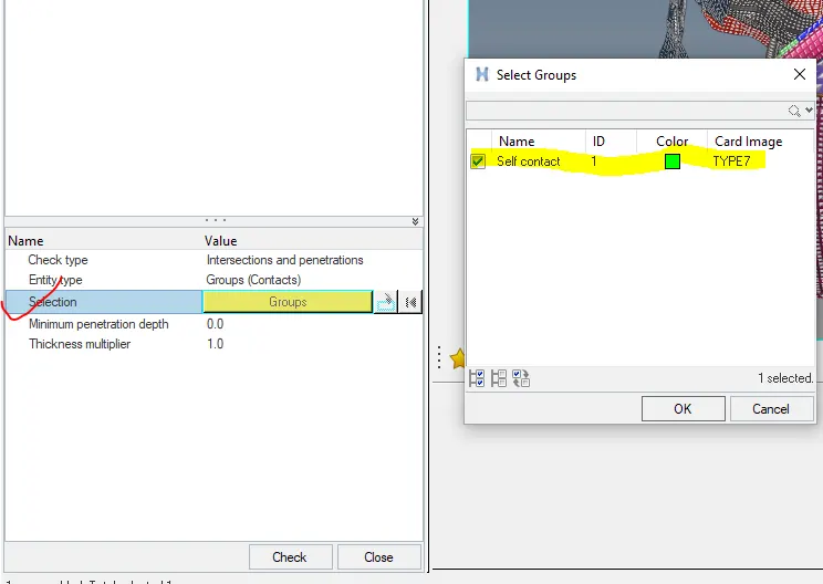
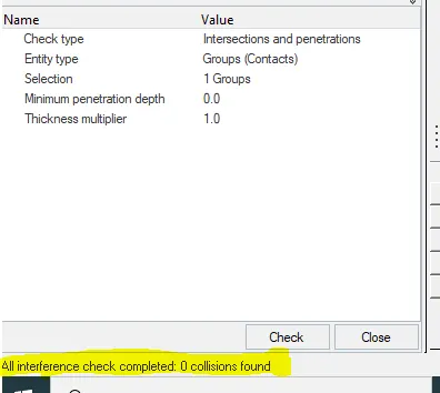
- Here penetrations are checked and it says that 0 collisions found that means there is no penetrations and intersections.
4.Correct the rigid bodies If any issues.
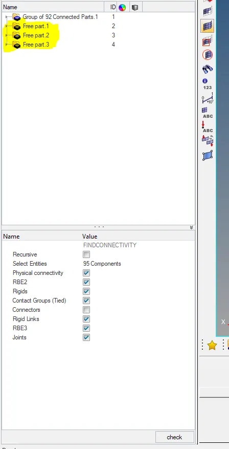
- For that we have to go to the tools >Find connectivity>click the check option so it will show them which parts are not connected as shown in the below images.
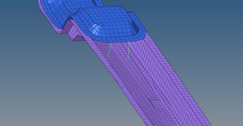
- If any flying rigid bodies are present we can fix it by rigid connections as shown in the below images.
5.Create a rigid wall with friction 0.1 as per reference model.
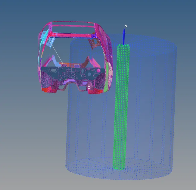
- To create the rigid wall goto >create rigid wall>cylindrical and rigid wall is created as shown in the below image.
- Then give the friction value is 0.1 as mention in the below image.
6.Compare the model weight with the reference model and use added masses to reach target weight of 700kg while getting CG about the required range.
- For that we have to go to the hypercrash there we can balance the required mass over there as shown in the below image.
7.Initial velocity is defined as the model of 20miles/hr.
- Here we have given the velocity to all nodes of the model as shown below images.
- For that create >Bcs>INIVEL there we can edit the card w.r.t the Global Axis.
- We have convert miles/hr to mm/ms (20miles/hr=8.94mm/ms).
8.Use model checker to ensure good quality.
- Here we have to check the model to ensure the good quality for that we have to remove if any unsupported cards are present.
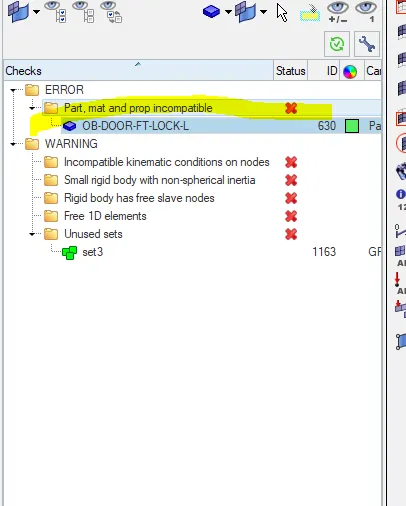
- We can fix the errors by auto-correct as shown in the above image.
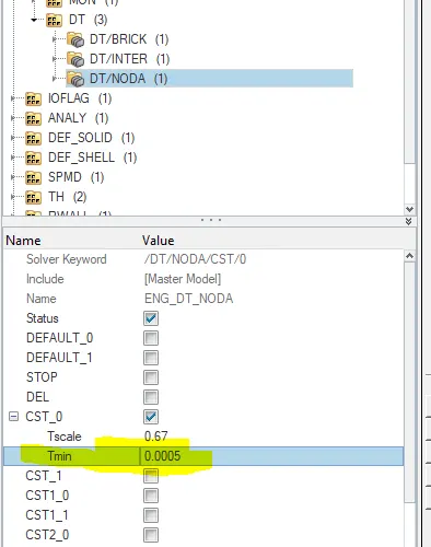
9.Timestep :0.5 to 0.1 microseconds.
- In the context of explicit analysis, the time step is the time required for a shock wave (governed by the speed of sound) to propagate across the smallest distance of the element. A run is a single model simulation and it starts at time zero and continues till the user-defined endpoint is reached. The basic time unit in the run is the time step.
- Here the time is in micro seconds we should convert in to the milliseconds.
10.Run time 80ms.
OUTPUT REQUESTS:
1.Section forces in the Cross members
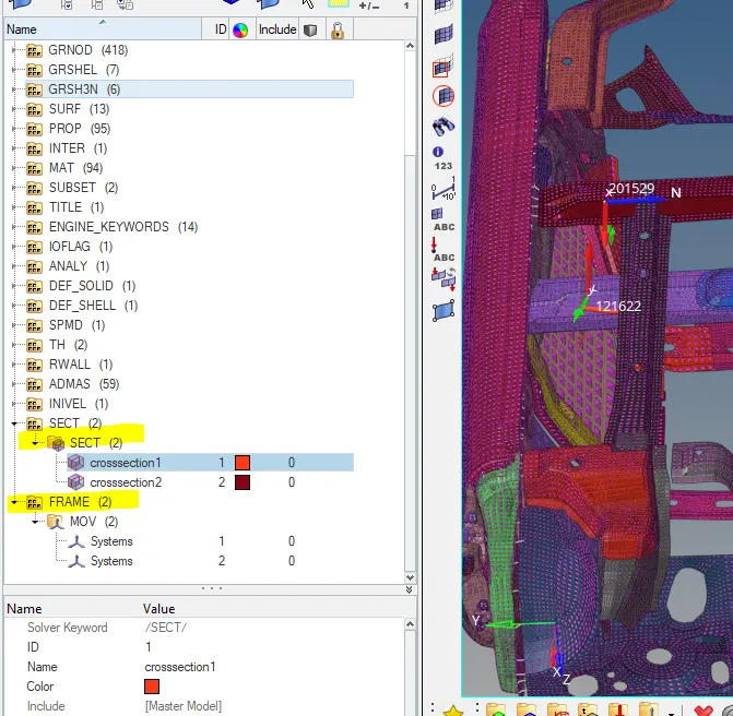
- Here we have to create the section forces on the two rail components as shown in the below images.
- First, we have created the sets in the model browser to select the set of elements on the rail components.
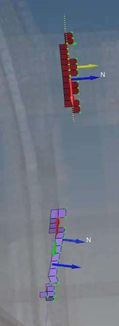
- Then come to the solver create the moving frame over there which has to normal and define the sets and Frame_Id over there which was created in the model browser.
- Then Cross-section is created as shown in the below image.
2.Intrusion at B pillar, hinge pillar and fuel tank region. Provide recommendation on what can help to reduce Fuel tank intrusion.
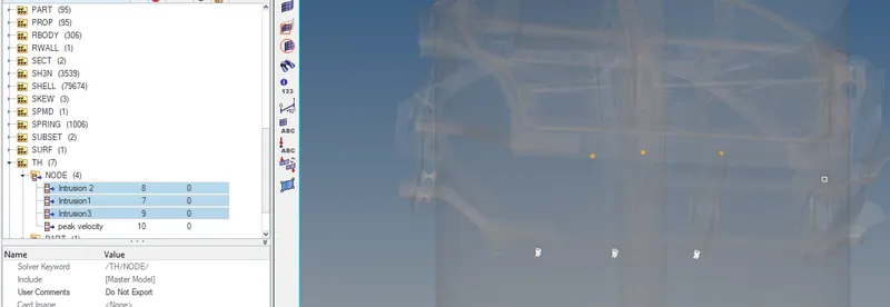
- Here we have to create the intrusions at the B pillar, Hinge pillar and the fuel tank region.
- For that go to the DT/NODA of TH then create the intrusions by selecting the node in their region as shown in the below images.
3.Peak velocity of an inner node of the door.
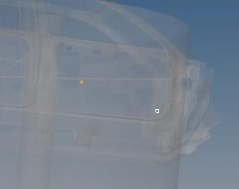
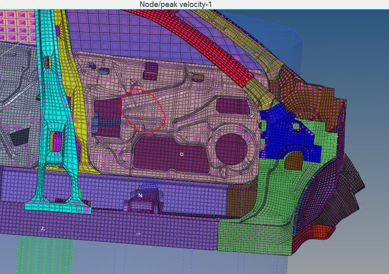
- For the peak velocity, we have to define the node on the door as shown in the below image.
PLOT RESULTS:
Animation:
Section Forces:
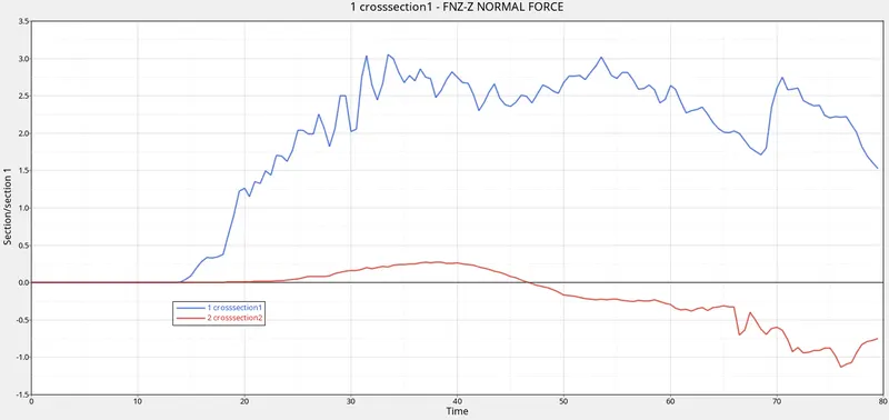
- If we observe the above graph the cross_section2 graph is in the negative direction because the more deformation occurring in the Cross_section2 rather than Cross_section1 as we observe in the above Animation.
- Here we have to choose the z-direction for the normal force acting on the Cross-section.
Intrusions For the Displacement:
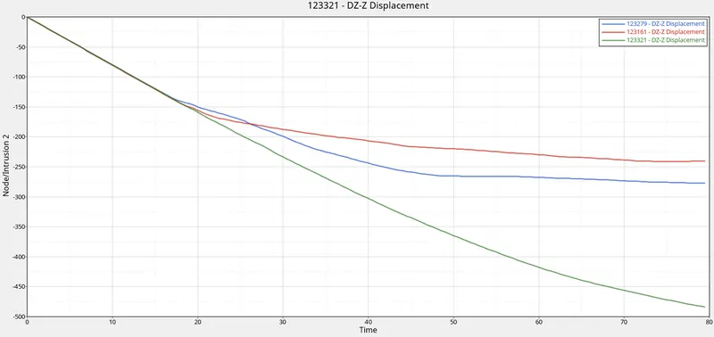
- Here we are given three intrusions at B pillar, Hinge pillar and fuel tank region to check the displacement.
- Here the max displacement is at the fuel tank (460mm).
- Minimum displacement is at the Hinge pillar(225mm).
- And displacement at the B pillar is(275mm).
Peak velocity of an inner node of the door:
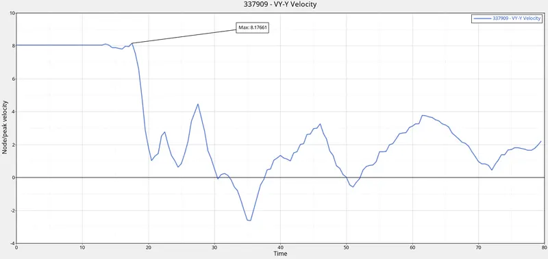
- If we observe the above graph it going in the negative direction as well because when the body hits the rigid cylinder after hitting there is a small deceleration and again it will impact the wall.
- Therefore the peak velocity of the given node is as shown in the above image is(8.17mm/ms).
Internal, Kinetic and Total energies:
Contact and Hourglass energies:
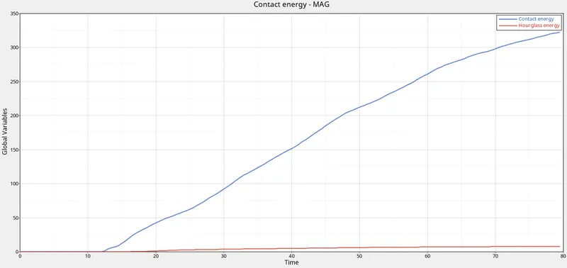
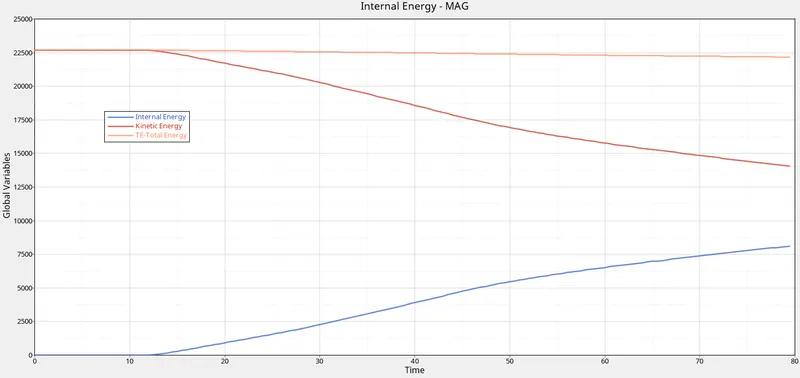
- As we know that when the car hits the rigid wall kinetic energy is decreasing and internal energy is increasing as shown in the above images.
- Then contact energy is also increasing and also there is hourglass energy is also increased a little bit then total energy will decrease w.r.t the hourglass energy.
CONCLUSION:
- If we observe the above graph the cross_section2 graph is in a negative direction because the more deformation occurring in the Cross_section2 rather than Cross_section1 as we observe in the above Animation.
- Here the maximum displacement is at the fuel tank (460mm).
- Minimum displacement is at the Hinge pillar(225mm).
- And displacement at the B pillar is(275mm).
- The peak velocity of the given node is as shown in the above image is(8.17mm/ms).
LEARNING OUTCOMES:
- Understood how to create Cross_sections and Skews.
- Creating Rigidwalls in the hypercrash with recommended parameters.
- Creating the Intrusions in A and B pillars as well as on the fuel tank region.
https://drive.google.com/drive/folders/1YAyGNOQRjTPJ7BgsGt_mJv4wgdw0Q0tH?usp=sharing