Assignment 7
- Explore tutorial number 9 and write a detailed report (50 marks)
- Build FRM Model for following configuration using FRM builder approach (50 marks)
- Bore 102 mm stroke 115 mm CR 17
- No of cylinder 6
- CI engine
- Twin Scroll Turbine
- GT Controller
- Run all cases
FRM Builder:
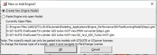
select frm builder from the tools section ,
choose create new engine model and ok
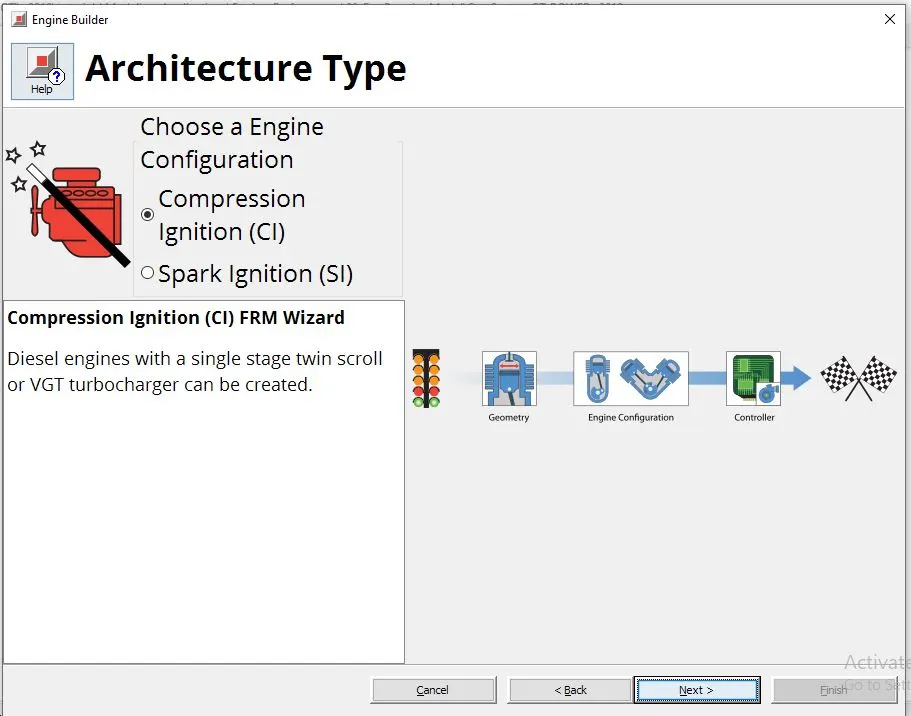
We need to select the type of engine , he choose CI engine and click next
Note here CI engine comes with a turbocharger which is also to be selected
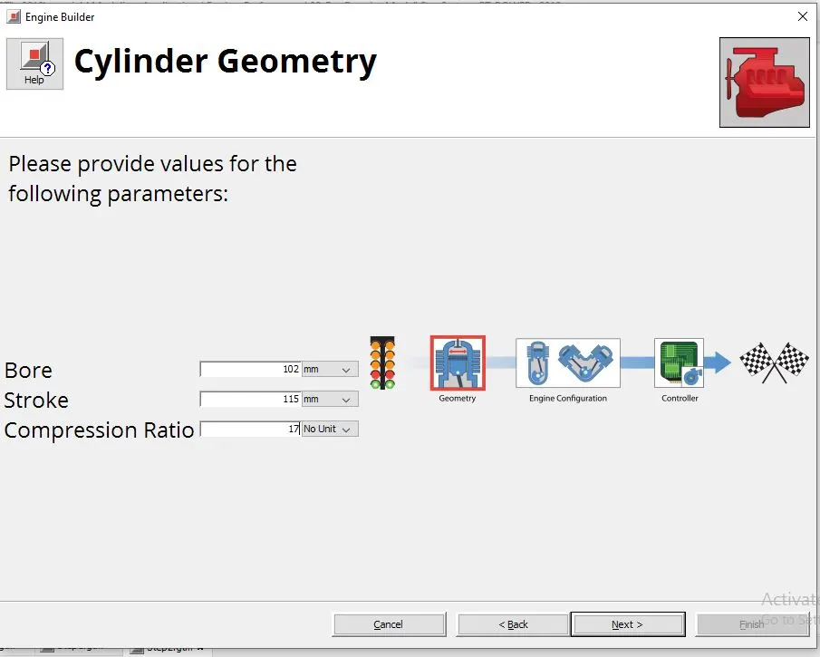
Provide the cylinder geometry details here
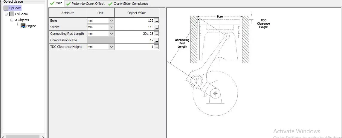
Bore = 102 mm
stroke = 115mm
Compression ratio=17
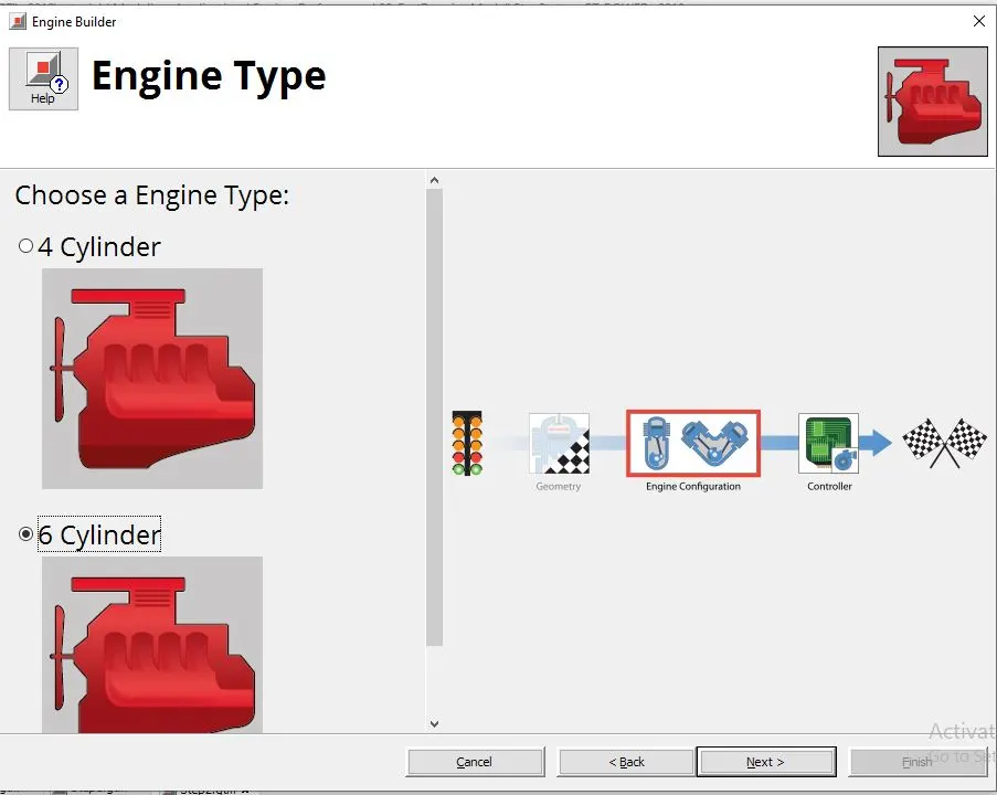
Now select the no. of cylinders for the engine
hhere choose 6 cylinder engine
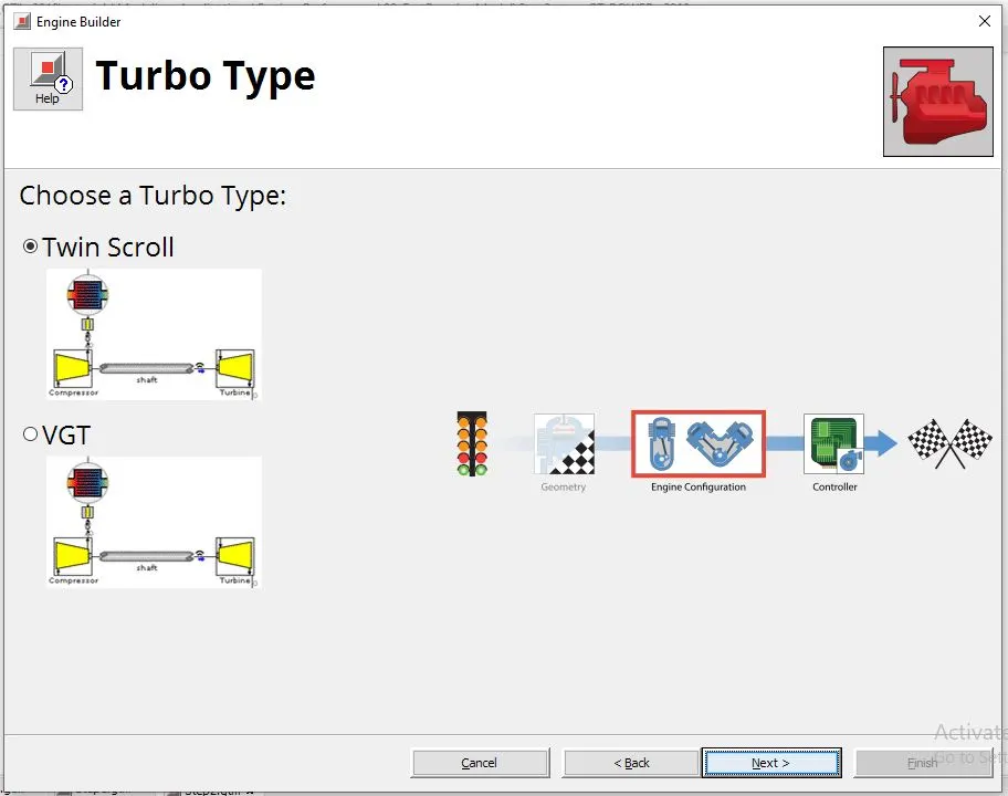
Select the twin scroll turbocharger
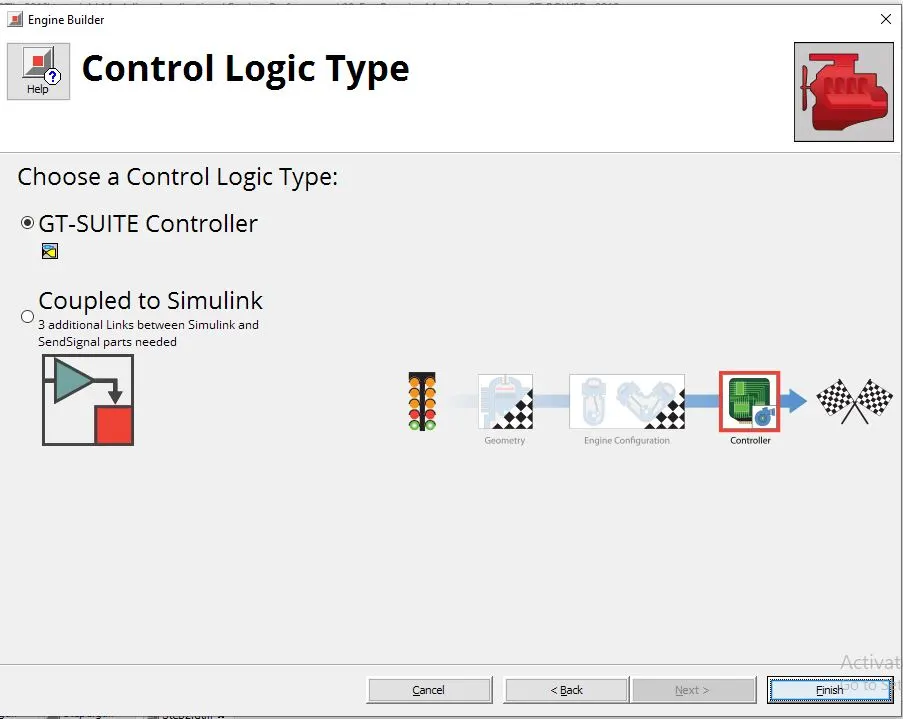
for the controller logic select the GT-SUITE Controller
the finished model will look as below
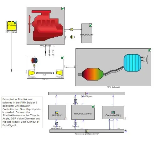
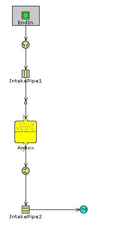
The intake system:
it has a intake pipe , air box for filter and intake pipe exit
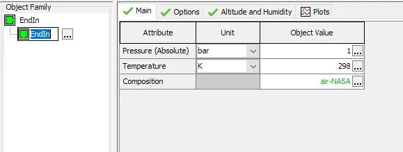
End environment:
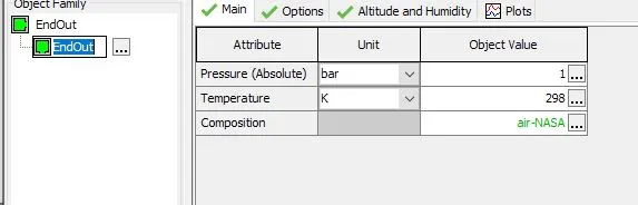
pressure = 1bar
Temp = 298k
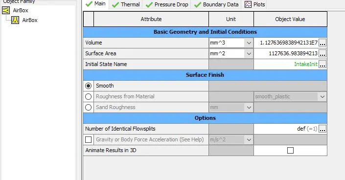
Air box:
the volume of the box is specified
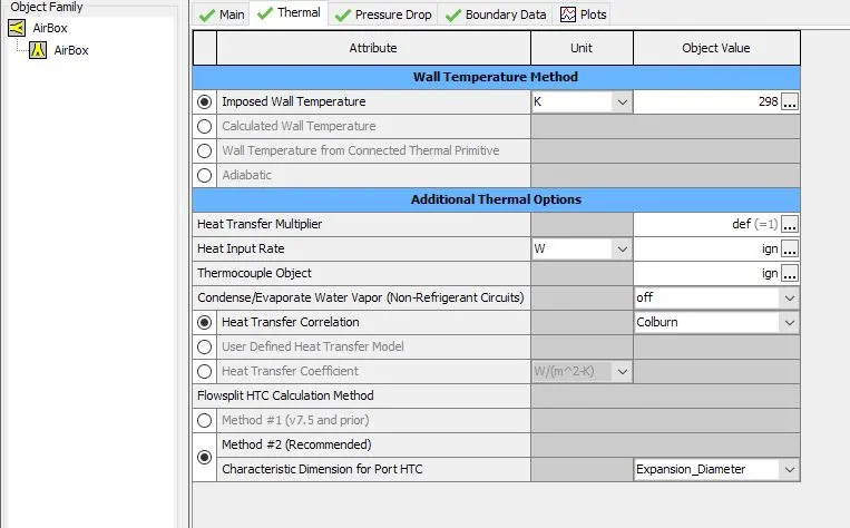
Thermal components of the box
an imposed wall temperature of 298k is imposed
FRM builder engine model:
it has a simplified intake manifold and 2 exhaust manifolds
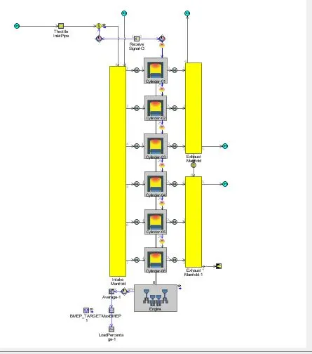
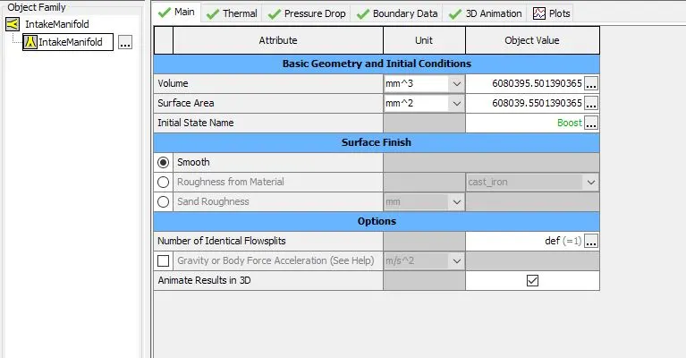
Intake manifold:
main attributes
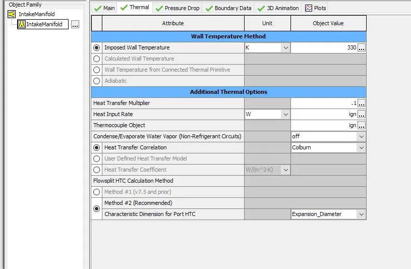
thermal attributes
wall temperature = 330k
cylinder geometry
as we specified
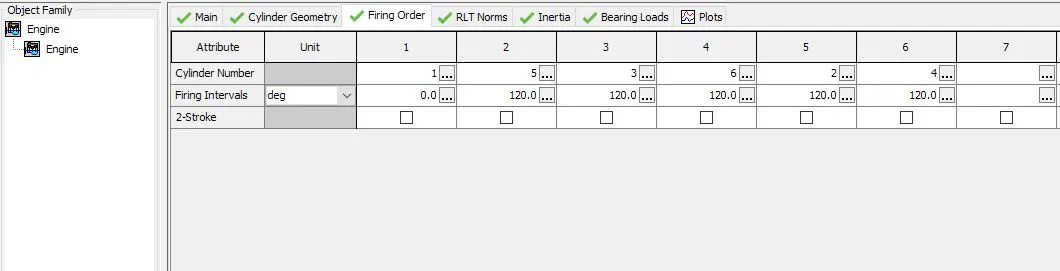
firing order:
1-5-3-6-2-4
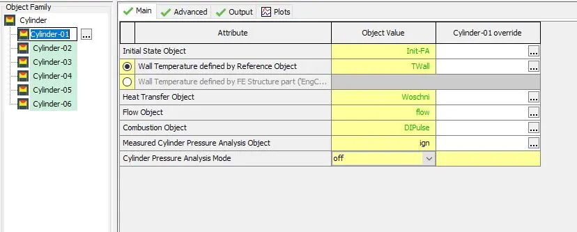
cylinder:
main attributes:
combustion object is DI pulse which is a non predictive combustion
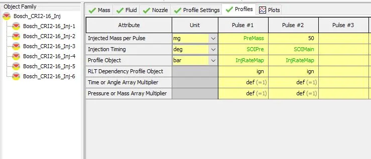
Profiles :
injected mass of fuel profile , injection timing and other profiles are specified
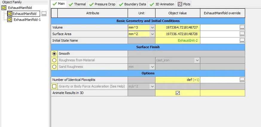
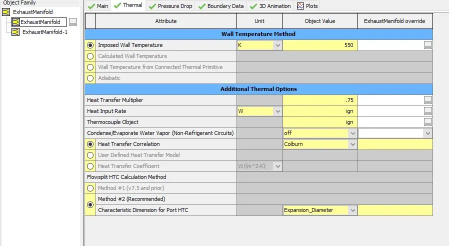
Exhaust manifold:
main attributes
Thermal attributes
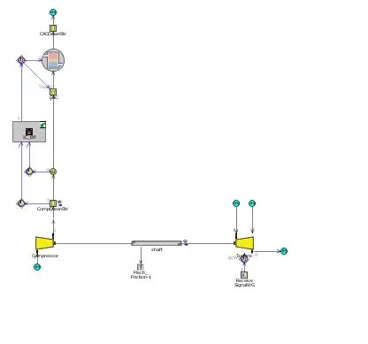
Scroll turbocharger:
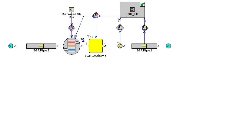
EGR controller
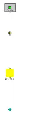
FRM outlet
End environment outlet:
outlet conditions
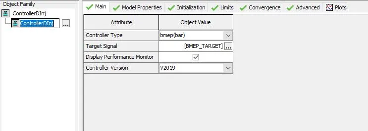
Diesel injector controller:
main attributes
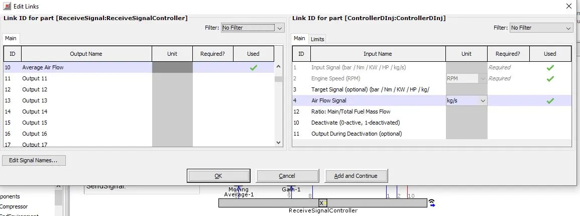
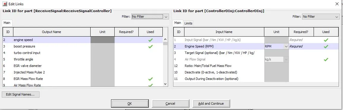
controller inputs:
air flow rate , engine speed ,BMEP
output signal :
injected mass rate
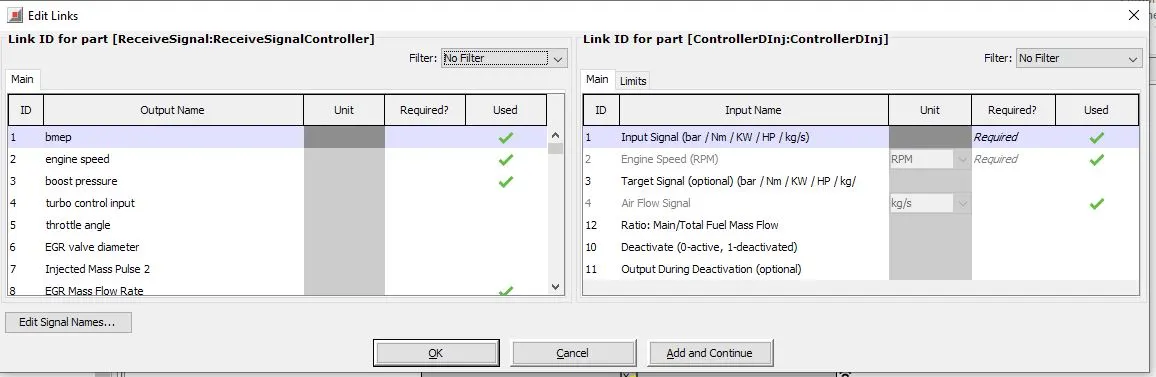
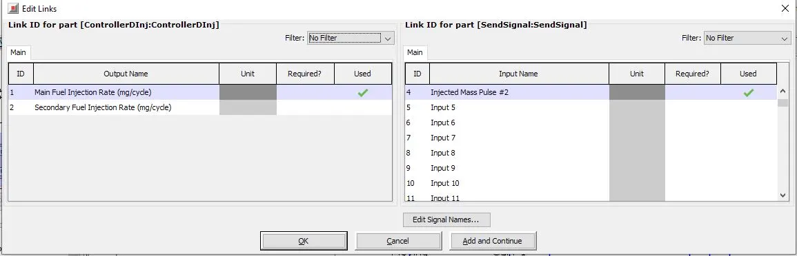
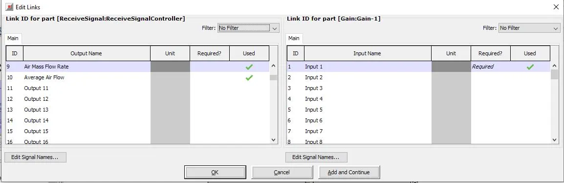
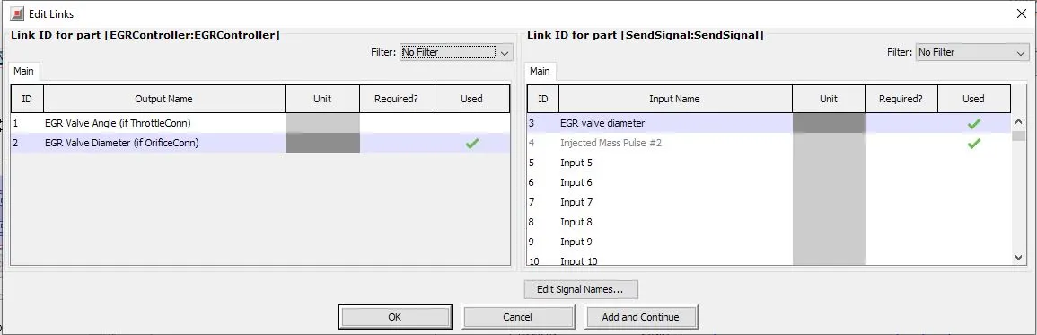
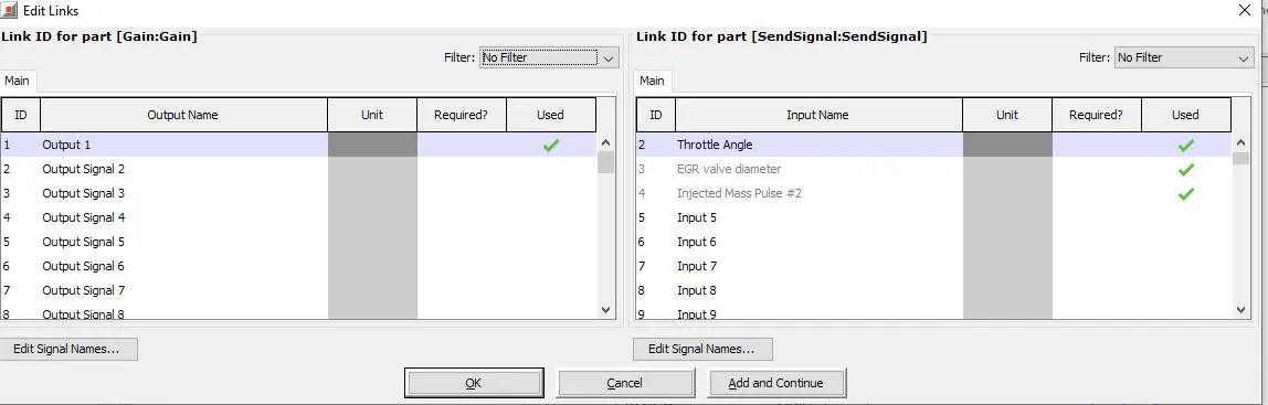
EGR controller configuration:
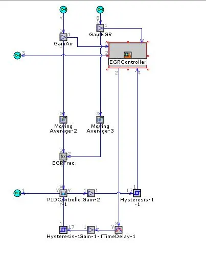
Input signals:
EGR Mass flow , Air flow rate ,
output signals:
EGR Valve diameter and EGR throttle angle
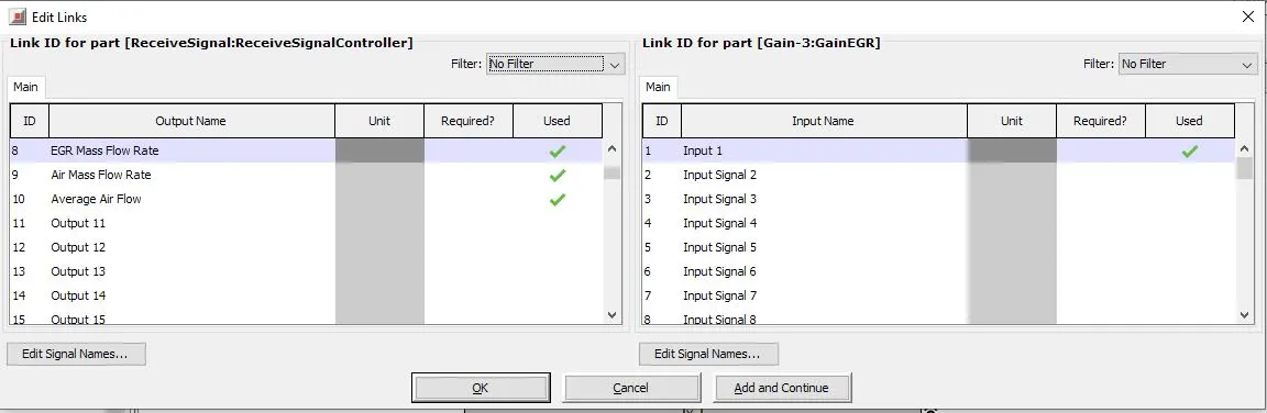
waste gate controller:
main attributes
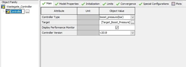
waste gate controller:
input signals:
boost pressure
Output signals:
wastegate diameter
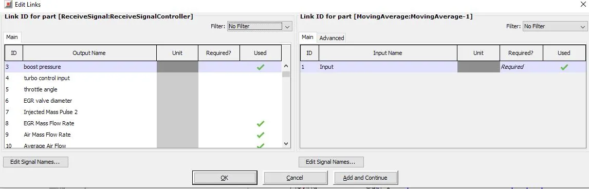
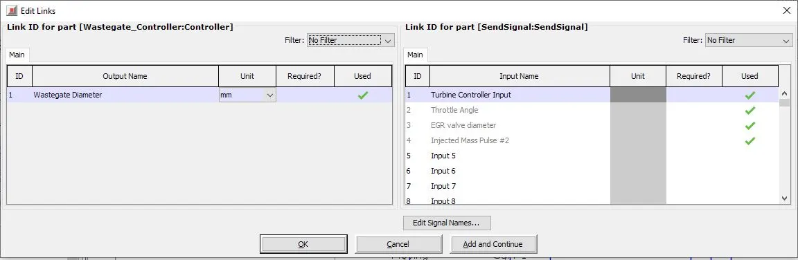
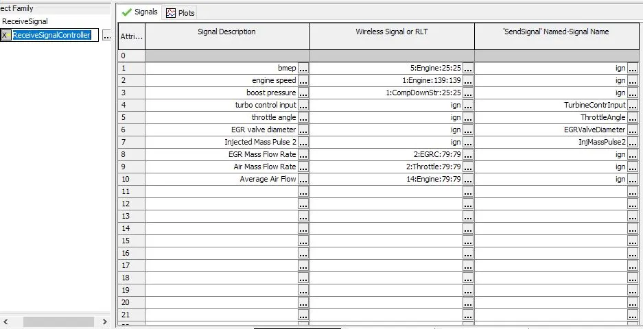
all reciever signals
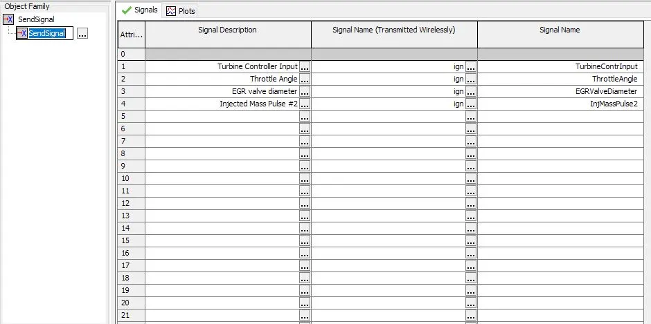
all output/send signals:
cases:
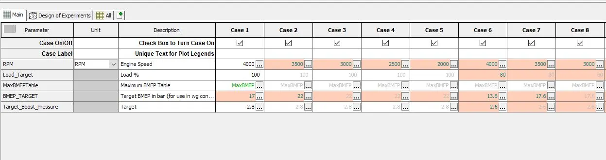
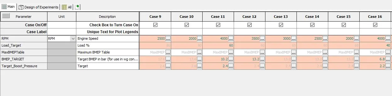
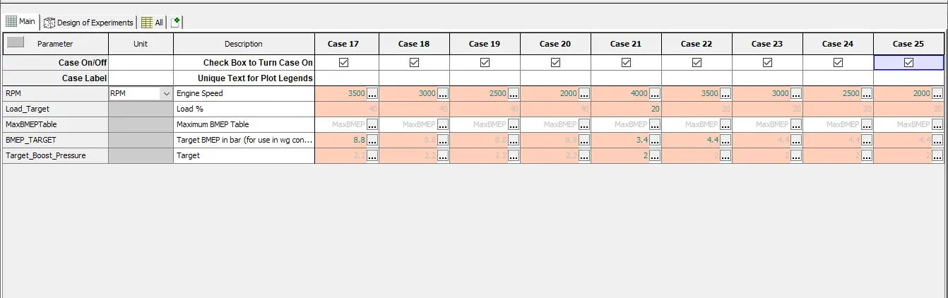
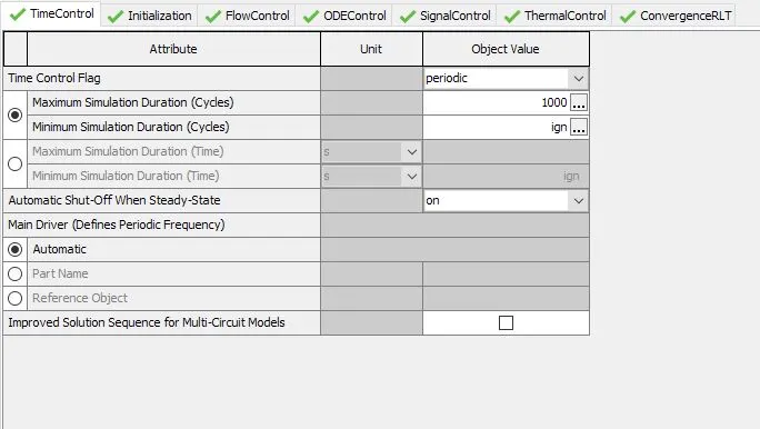
Run control:
max duration = 1000 cyles
flow simulation :
Time elapsed
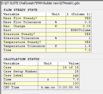
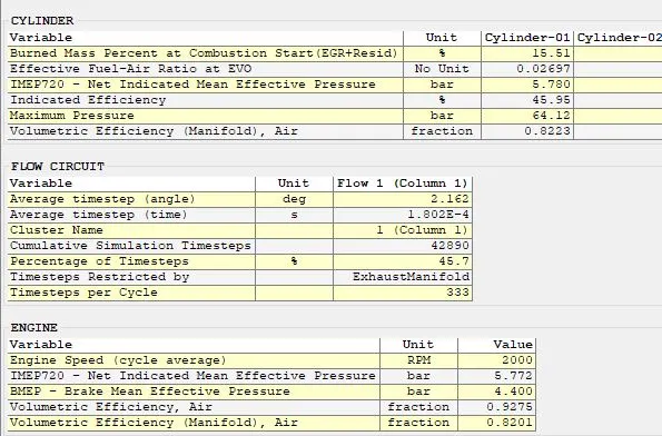
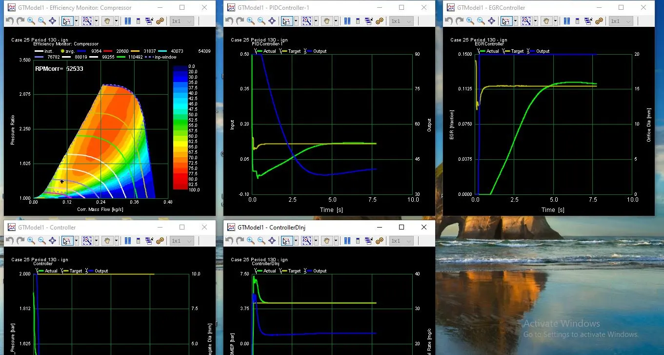
Monitors:
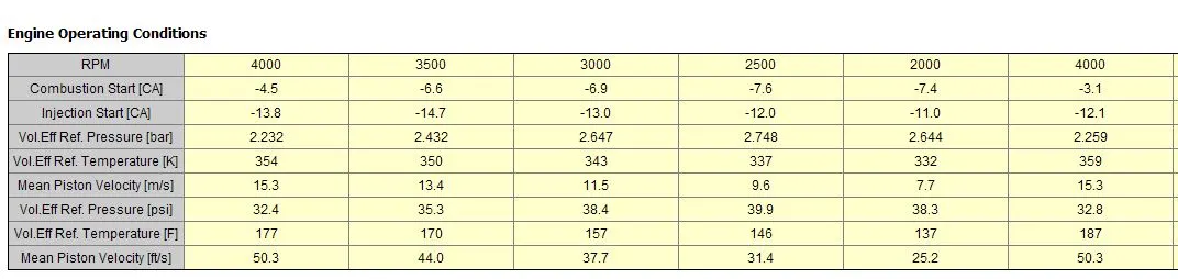
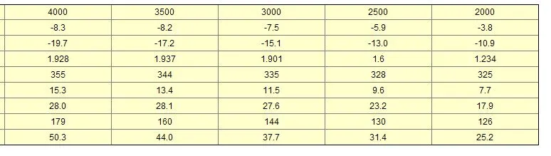
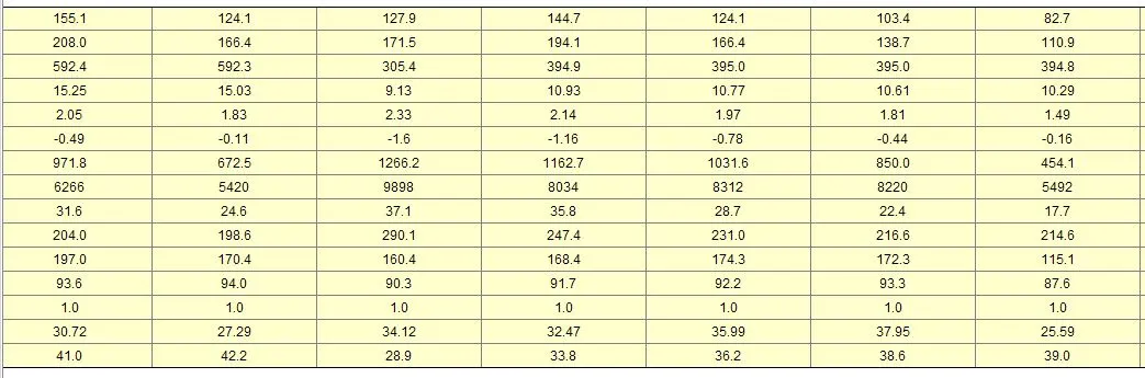
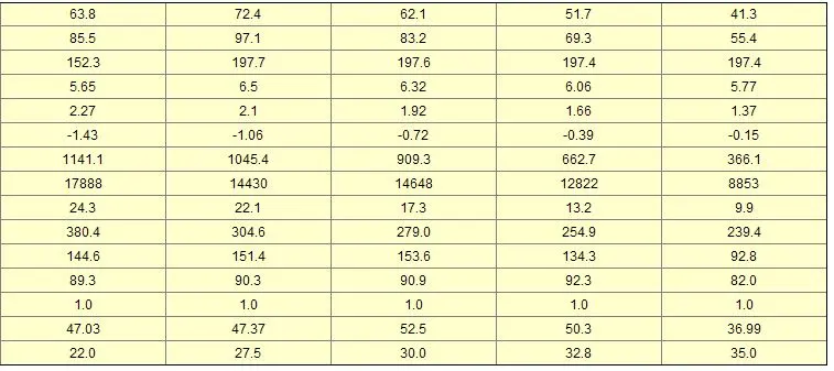
Engine operating conditions for all cases:

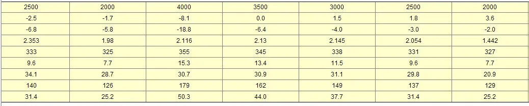
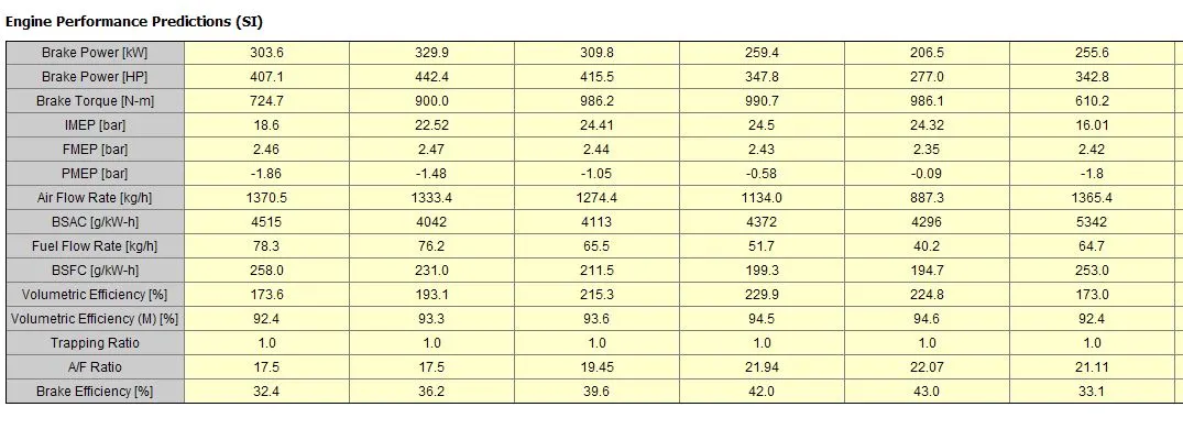
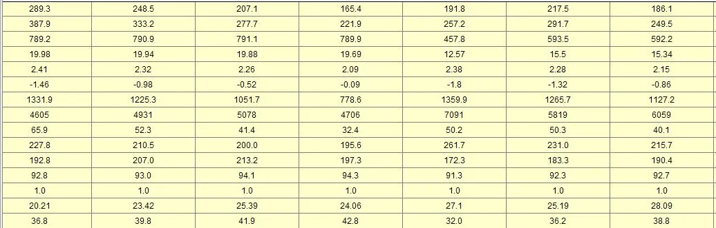
Engine perfromance predicitions all cases:
the air flow rate decreses when the bmep target is reduced
this also helps in reducing the bsfc ,
the volumetric efficiency increases with decrease in bmep target and air flow rate
FRM CONVERTER:
from the tools , select the FRM converter
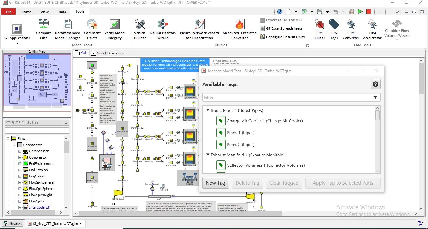
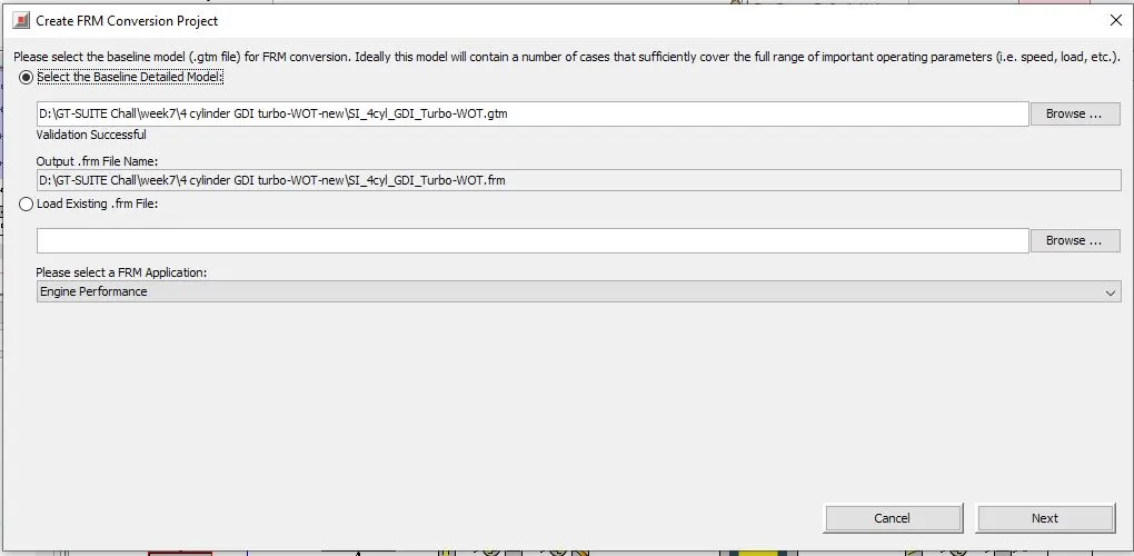
select the baseline model whhich needs to be reduced here it is 4cylinder -GDI-Turbo-WOT
and clcik next
for checking the accuracy we need to identify the important parameters which are crucial hence select those parameters
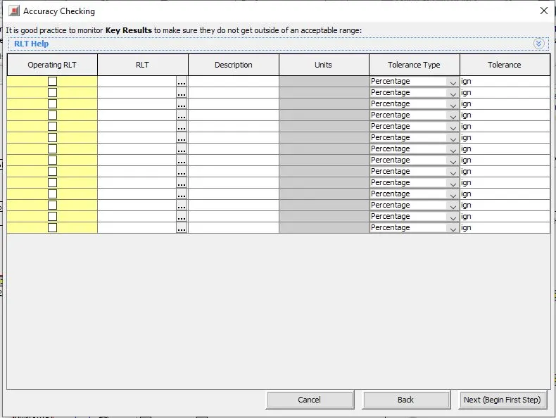
all the variable are identified for checking the accuracy once done , select click next
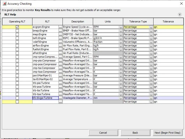
Model reduction step1 :
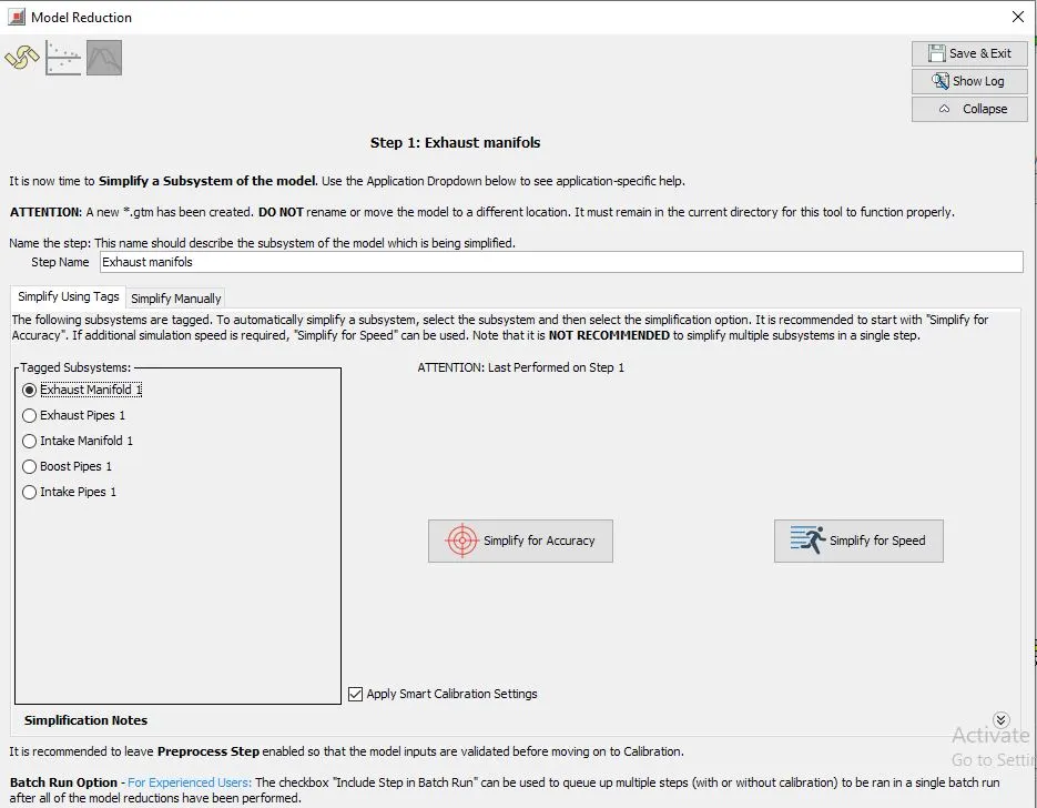
this template will be opened
choose exhaust manifold , give step name and clikc on simplify for accuracy
exhaust manifold will be simplified
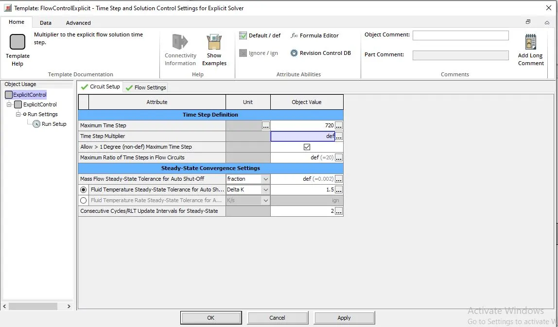
go to run setup - explicit control and
max time step = 720
this is simplified exhaust manifold
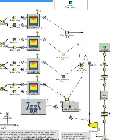
click on exhaust manifold port run
main attributes
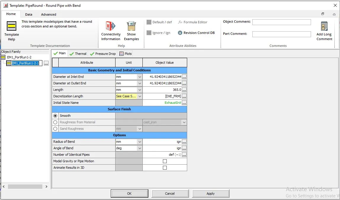
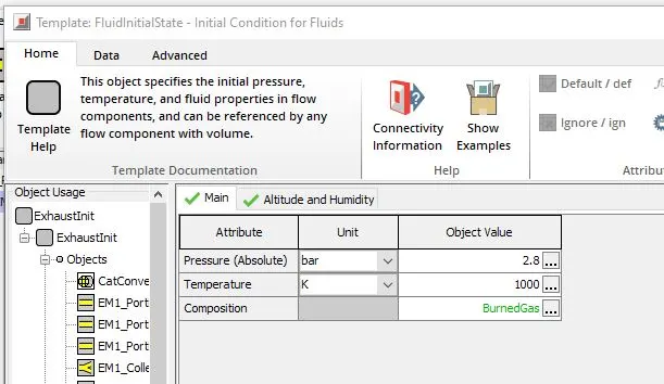
initial conditions:
pressure = 2.8bar
temperature = 1000k
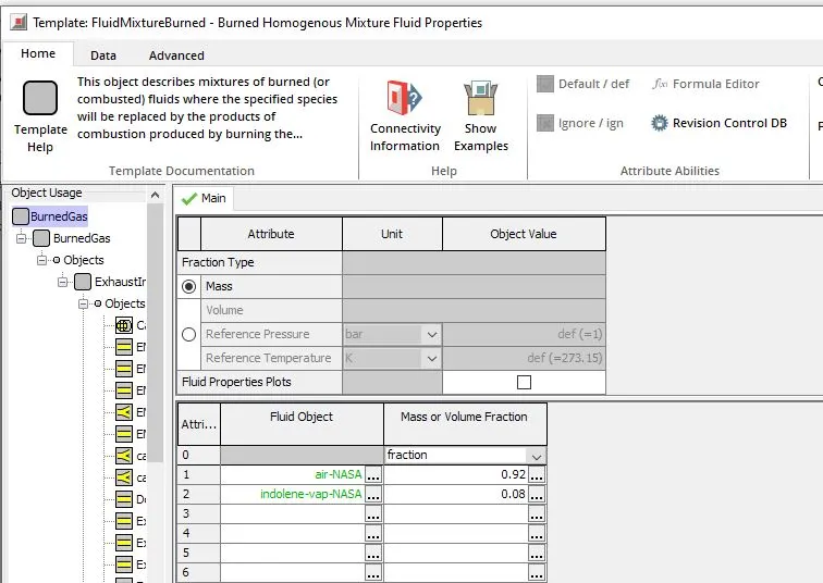
burned gas components
thermal conditions:
imposed wall temp = 550k
heat transfer multiplier is added in cases as parameter
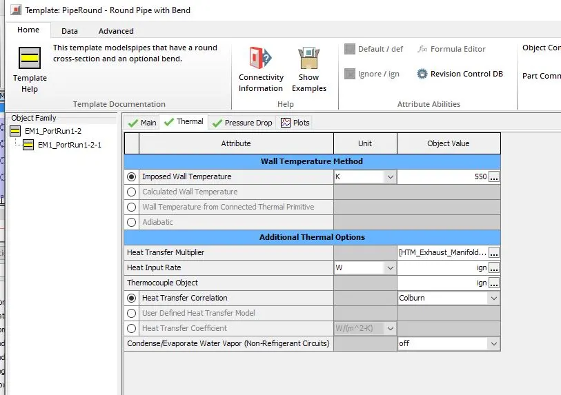
check in cases a value of 1 is specified
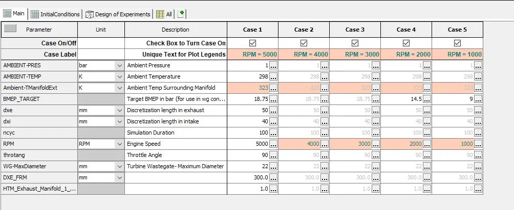
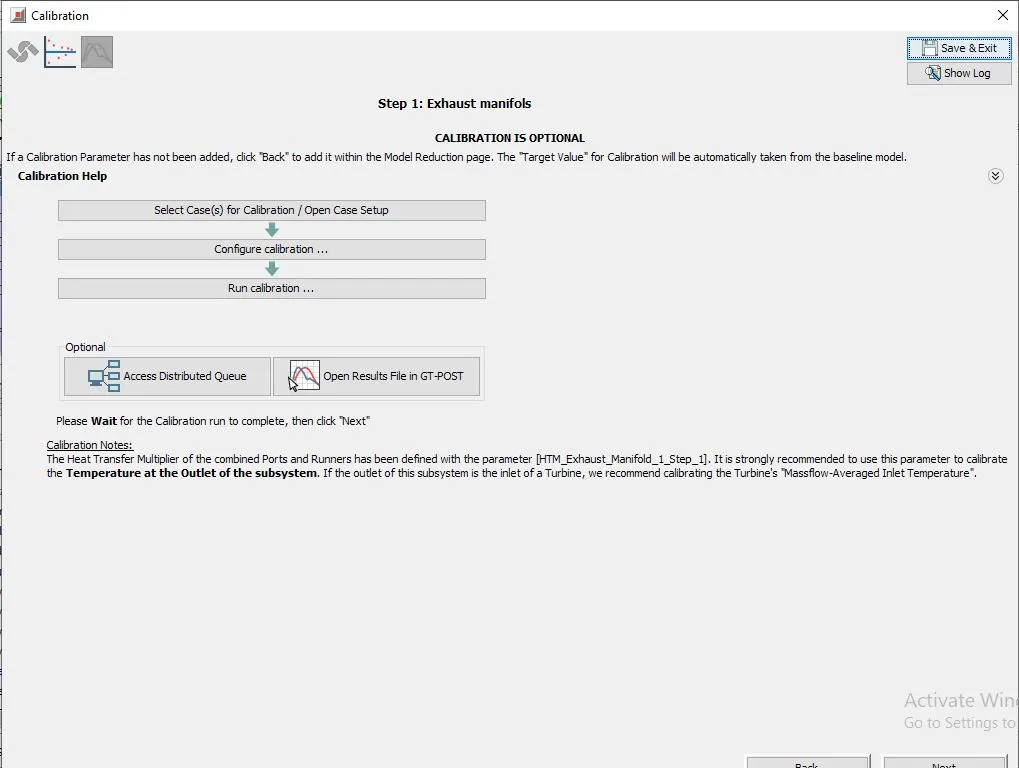
after cchecking all those click on calibrate
this template will araise
click on configure calibration
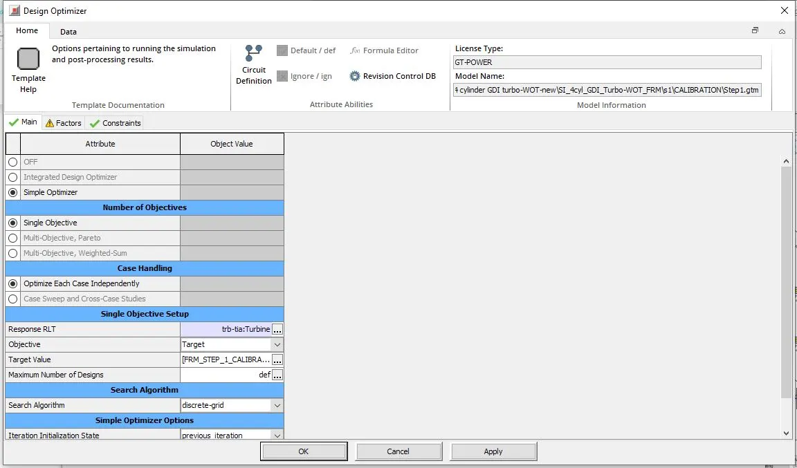
design optimizer will be opened
in response rlt : select trb-tla:Turbine
in factors select the lower and upper limit
lower limit=0.95
upper limit = 2.8
resolution = 2.0%
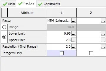
then click on run calibaration after calibration is over , this window will be openend
click on open key RLT plots in GT-POST
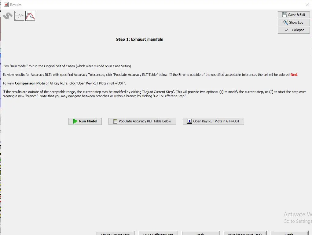
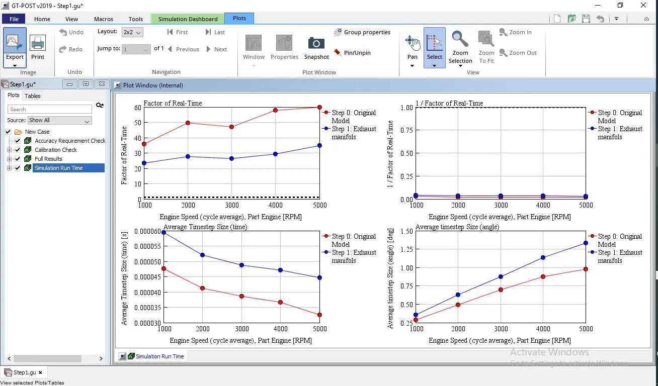
in GT post
click on the simulation runtime to view the factors
factors of real time vs engine speed graph is generated
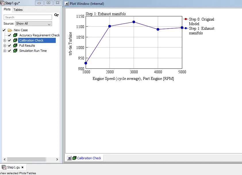
calibration check for the exhaust manifold:
got to tge simplified exhaust manifold
select the flow split template of EP1_PDROP1-1 right click and select combine flow volume wizard
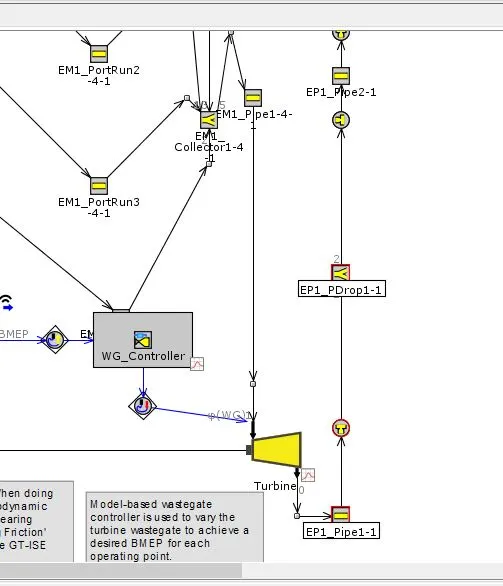
combine flow volumes wizard is opened:
leave everything as default and clikc on next , next and finish
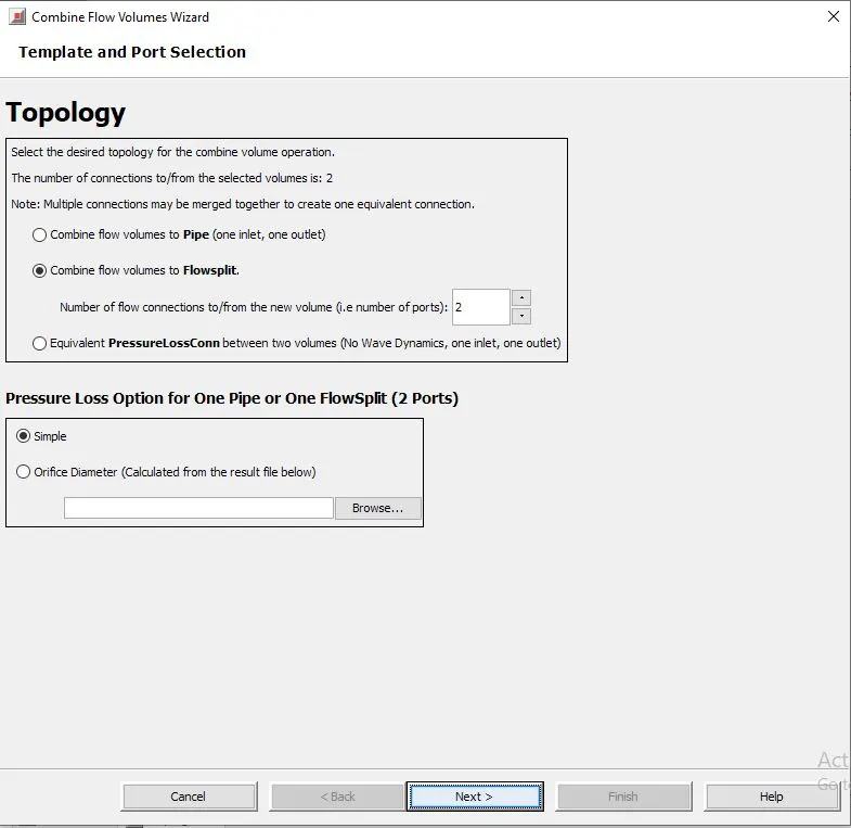
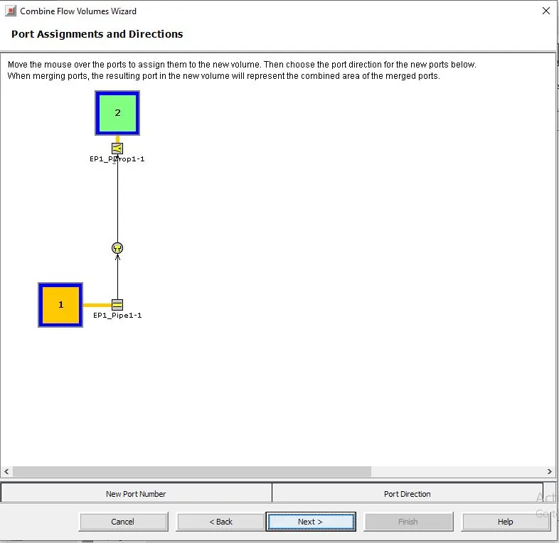
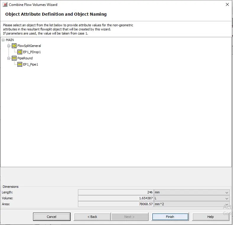
in combine flow volume wizard this window will be opened
select the EP1_Pipe1 and name object as EPFS and finish
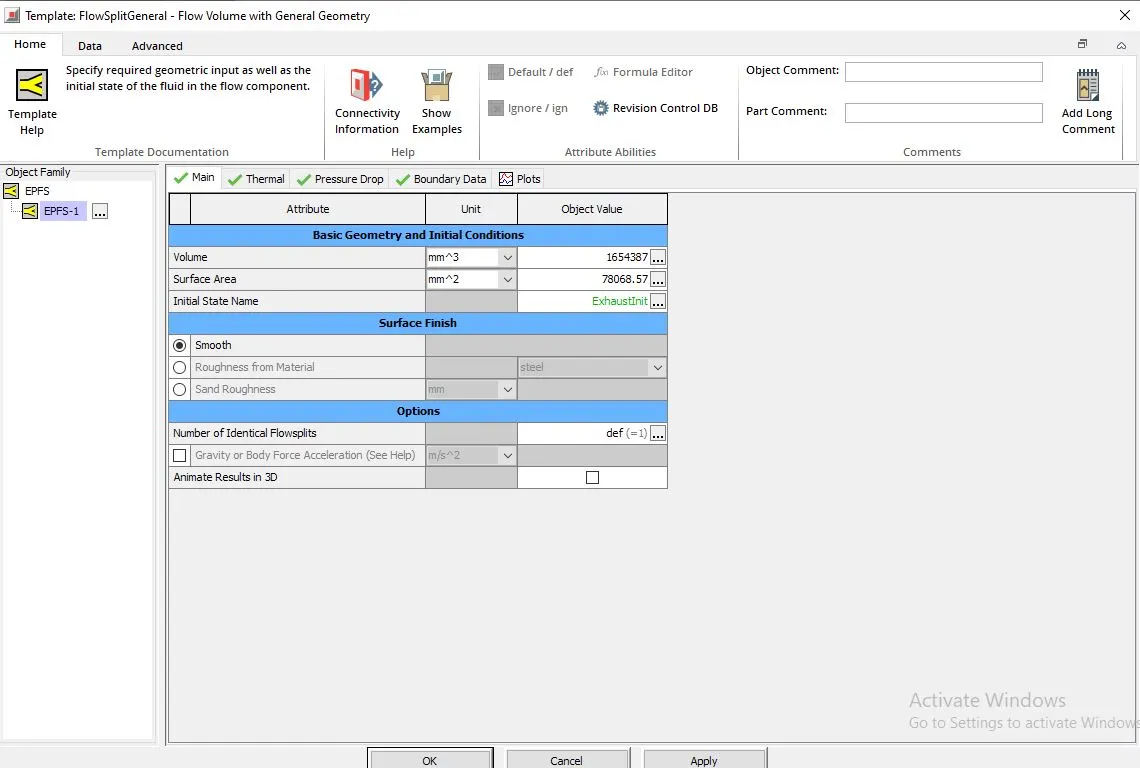
click on EPFS-1
main attributes :
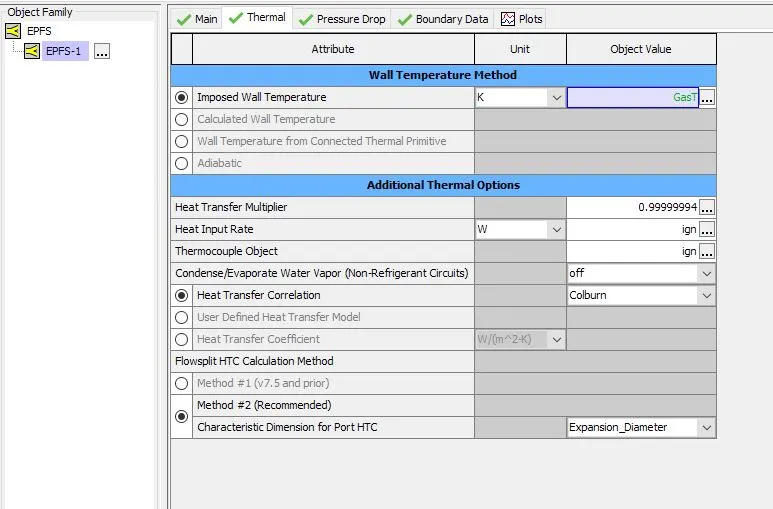
thermal attributes:
imposed wall temperature : choose GasT
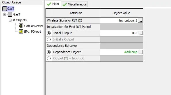
GasT attributes:
for catalytic converter:
the wireless signal or RLT(x) is average temeprature
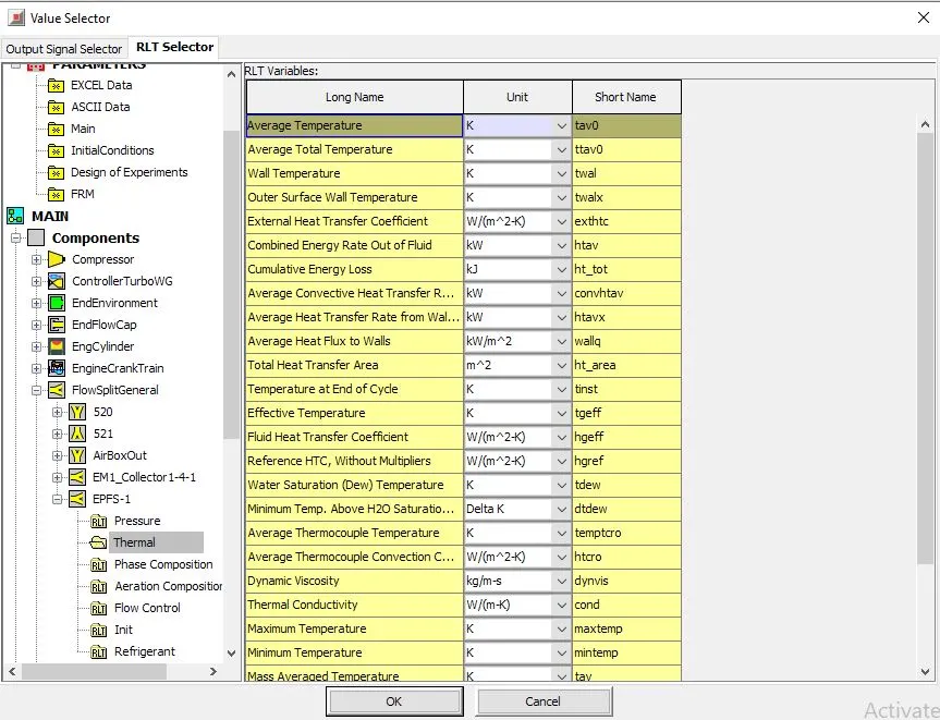
similarly for EP1_PDrop1
the RLT selector is average temperature
in case setup , the exhaust pipe diamter is taken as a parameter , the value is arbitarily fixed at 40mm
after checking case setup , run the model by click on run model
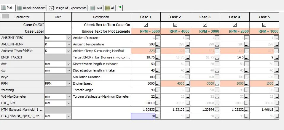
after the first step where exhaust manifold is reduced , calibrated and run , step2 model reduction window will automatically be directed ,
here select the exhaust pipe(which is to be reduced) give the step name as Exhasut pipes , after that click on simplify for accuracy , the exhaust pipes will be reduced and the reduced model can be checked by collapsing the window
after that , click on calibrate will take us to the calibration window
here we can click on select case for calibration/open case setup and check the cases in case setup
after that, clcik om configure calibration
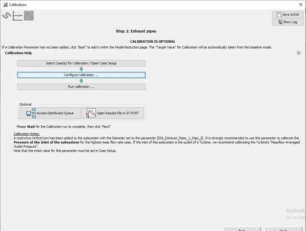
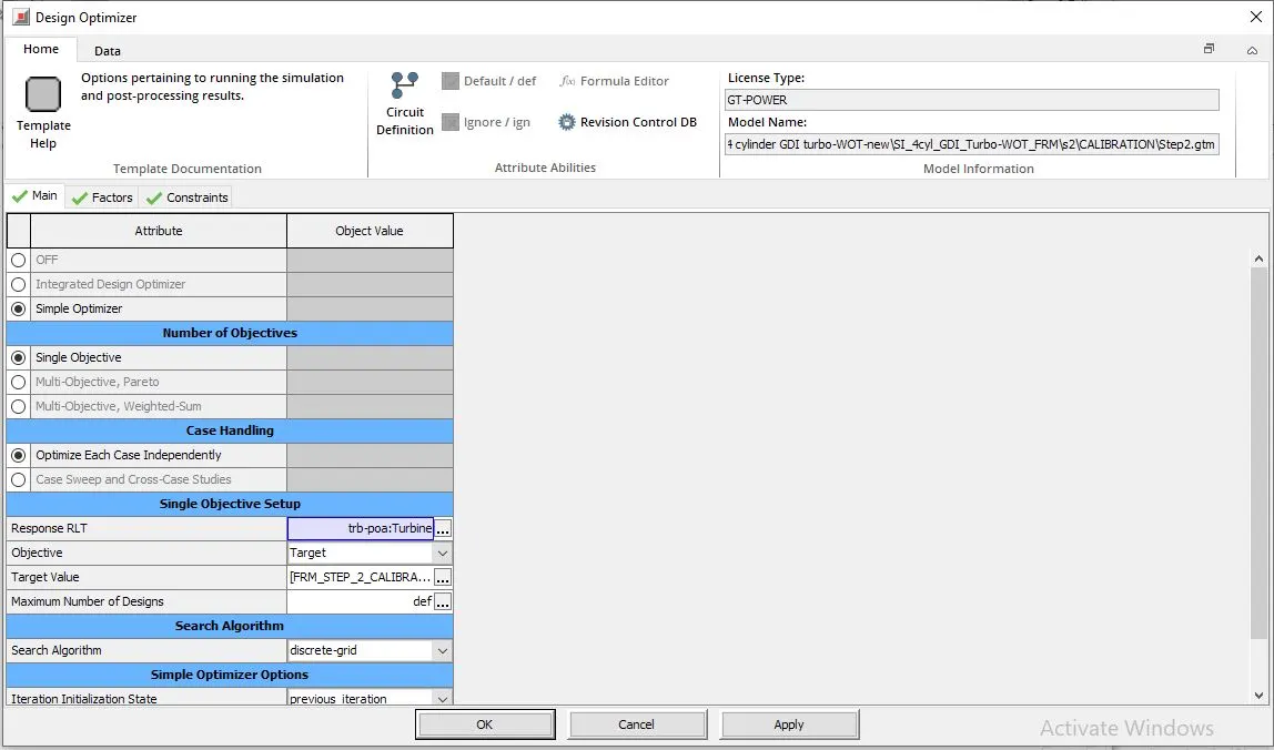
design optimizer will be opened
change respnse RLT to trb-poa:Turbine
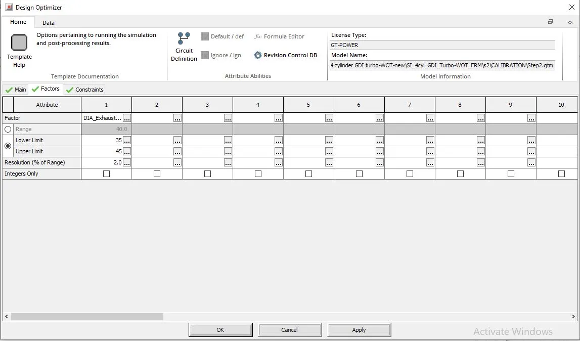
in factors,
set lower limit=35
upper limit=45
after that click on run calibration
Results window will be opened after calibartion
click on run model
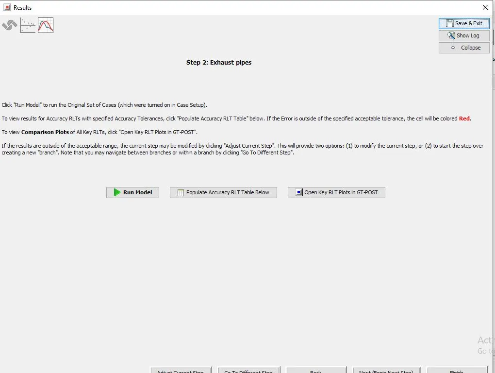
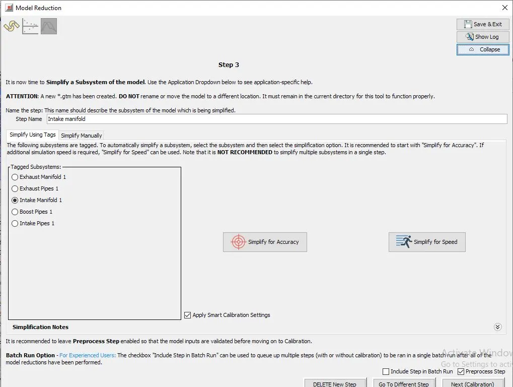
After running the model , it will redirect to step3
select intake manifold and name step as intake manifold
click on simiplify for accuracy
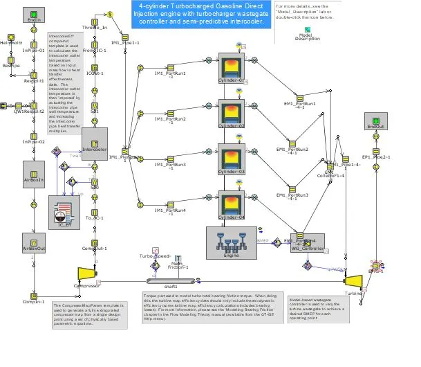
this is the simplified main model after intake manifold is reduced
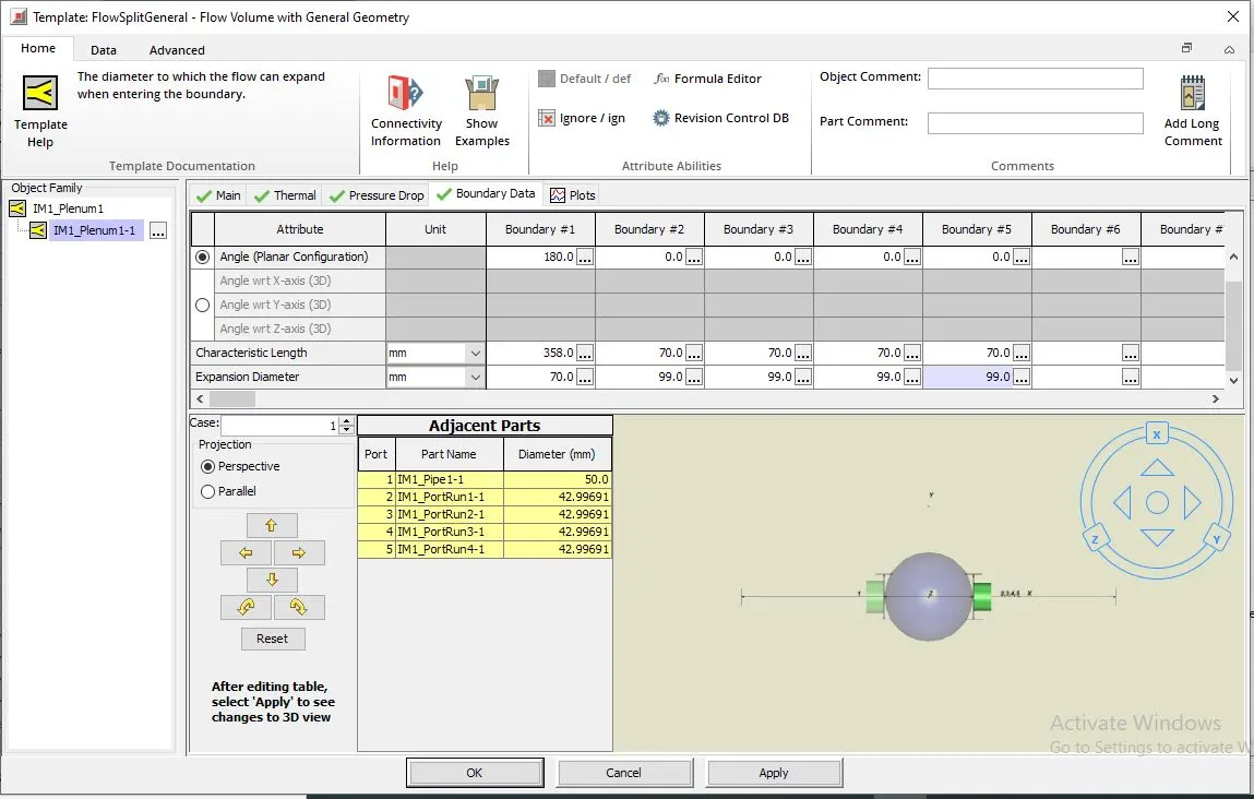
go to the simplified intake manifold plenum
IM1_Plenum1-1
main attributes:
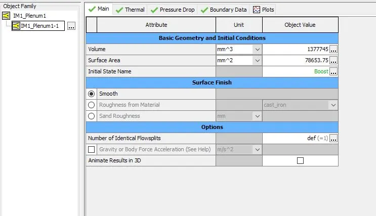
Thermal attributes:
initial wall temperature = 350k
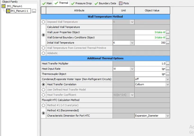
Boundary data:
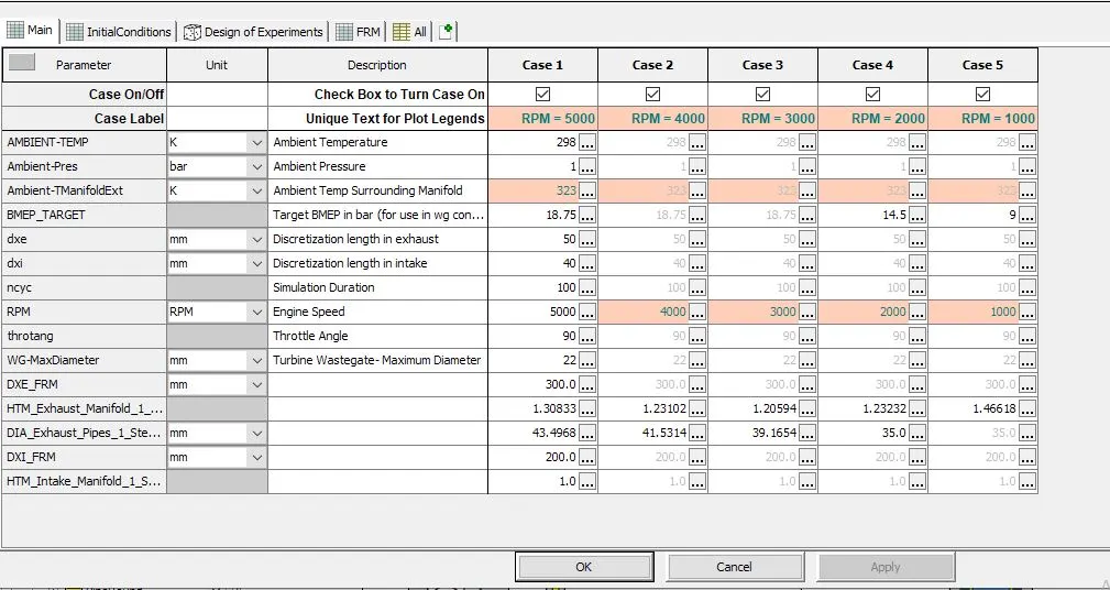
cases setup:
heat transfer multiplier for intake manifold is taken as 1.0
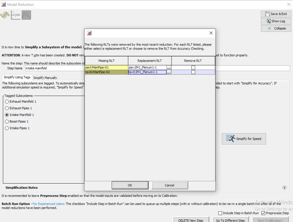
once the intake manifold is simplified some of the components will be deleted hence we need to replace them
so replace the missing parts with the present for accuracy checking
then click on ok
then click next calibrate
open case setup and check the cases and parameter set.
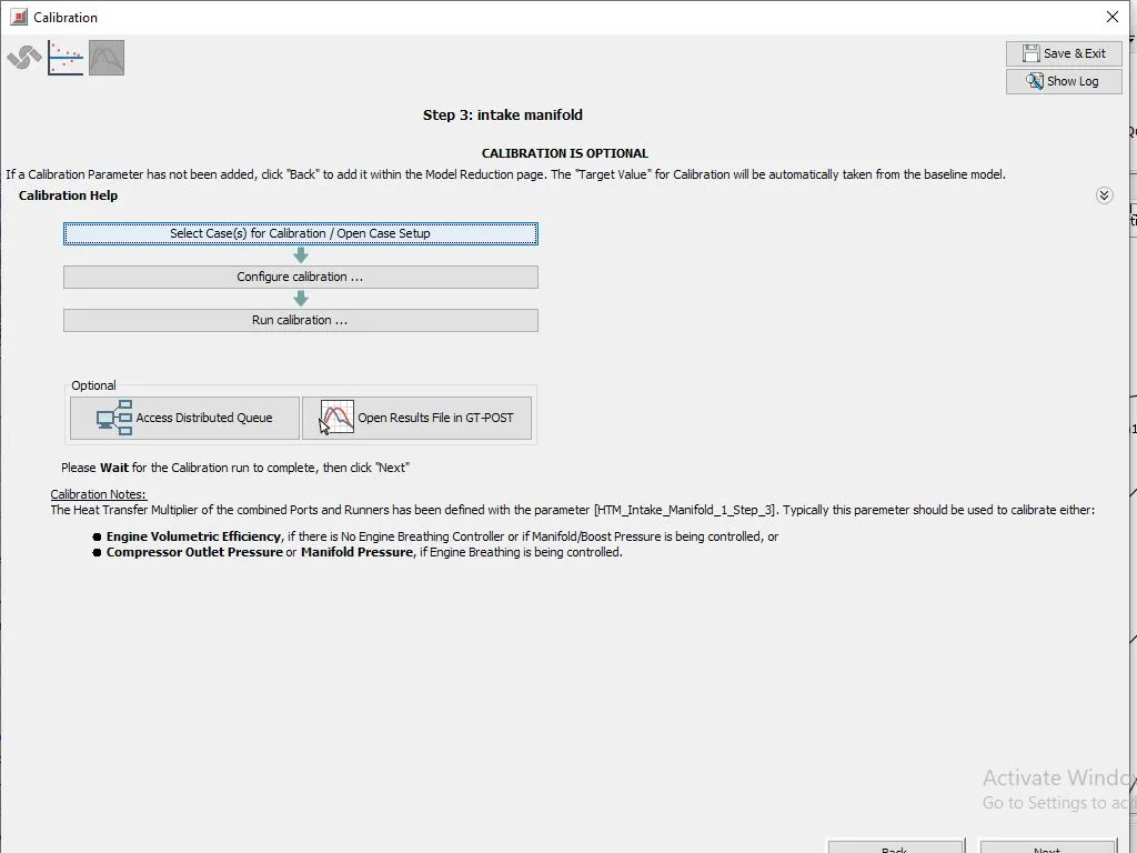
go to configure calibration , design optimizer will be opened
change response RLT to cmp-poa:compressor
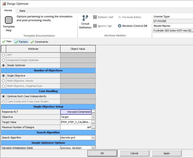
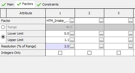
in factors:
lower limit = 0
upper limit = 1.1
resolution = 2%
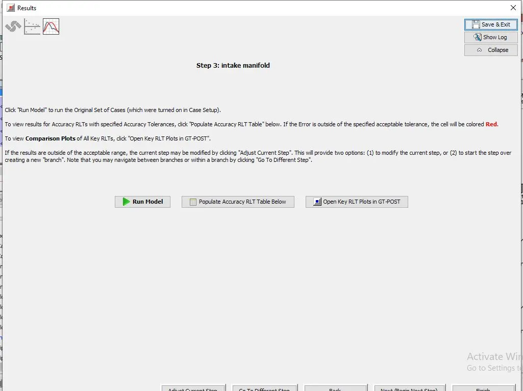
run calibration
after that results window is opened
click on Run model and close
step4 :
model reduction window for step4 will be opened
choose subsytem as boost pipes and give name for step as compressor outlet pipe
click on simplify accuracy
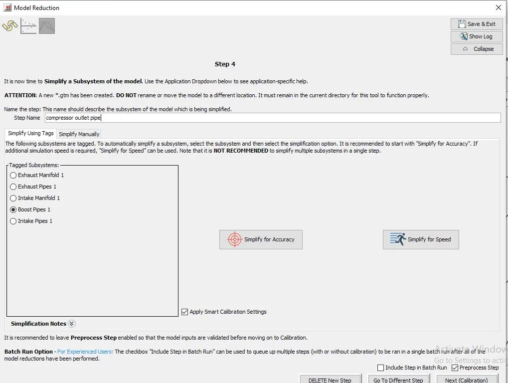
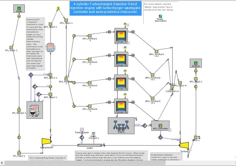
reduced model:
here note that the intercooler effectiveness template is not connected via signals
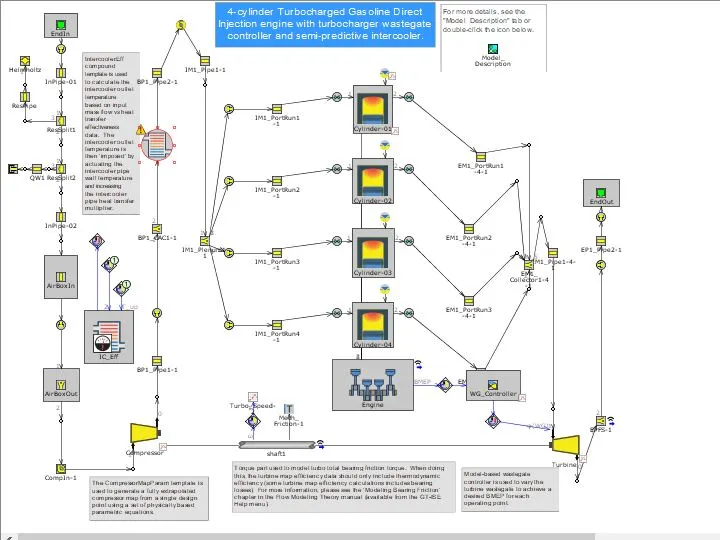
click on the intercooler pipe
BP1_CAC1
imposed wall temperature is 300k
heat transfer multiplier = 8.984505
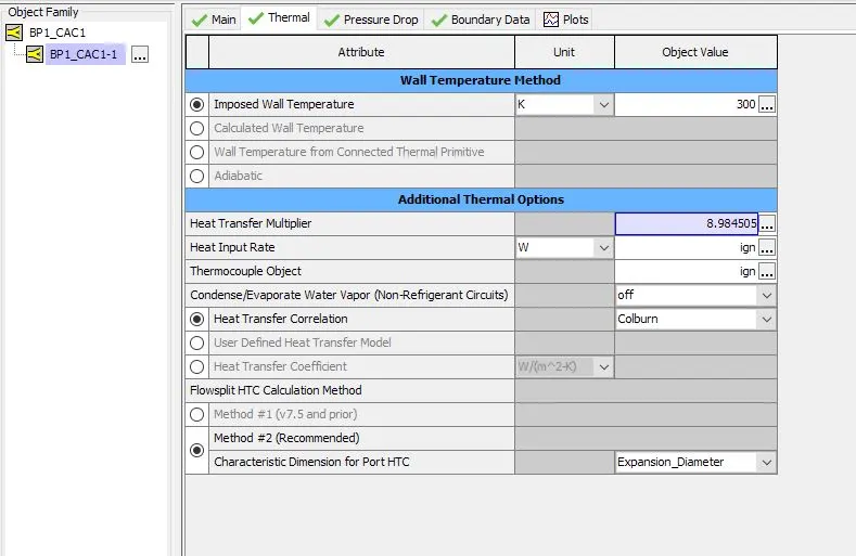
since the effectivenss template is not connected via signals we need to connect it as shown below
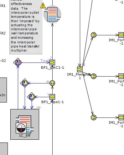
click on heat exchanger connection :
diamter is taken as a parameter
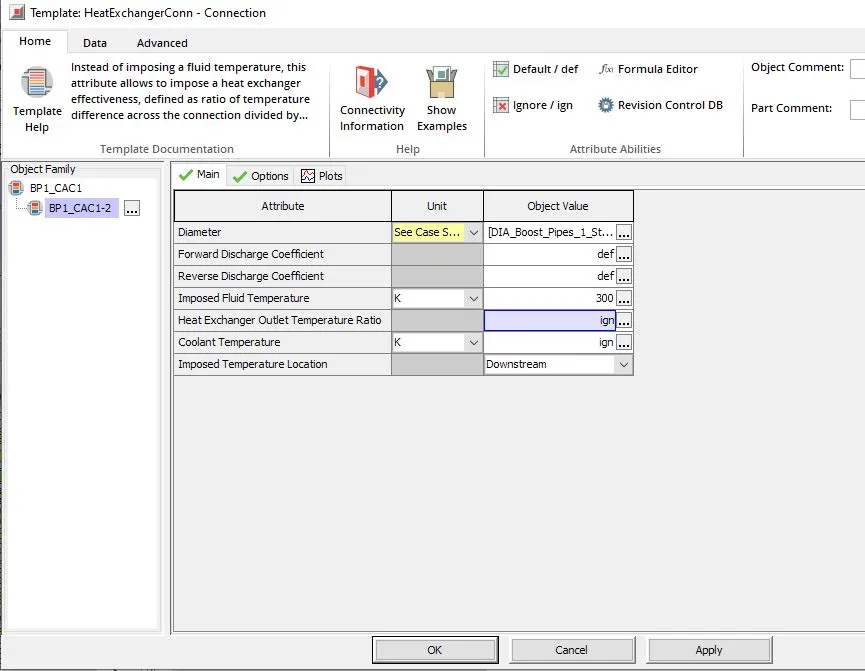
boost pipe diameter is taken as 35mm
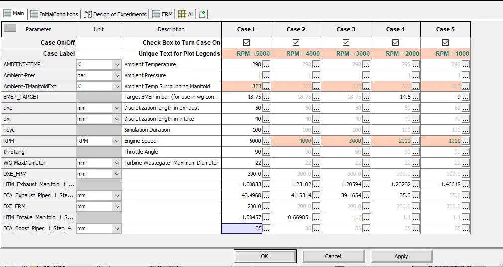
click on next calibrate
calibration (optional) window will be opened click on configure calibration:
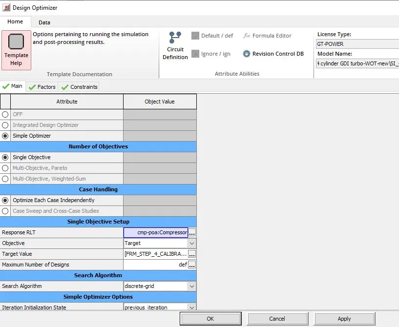
design optimizer is opened
Response RLT = cmp-poa:compressor
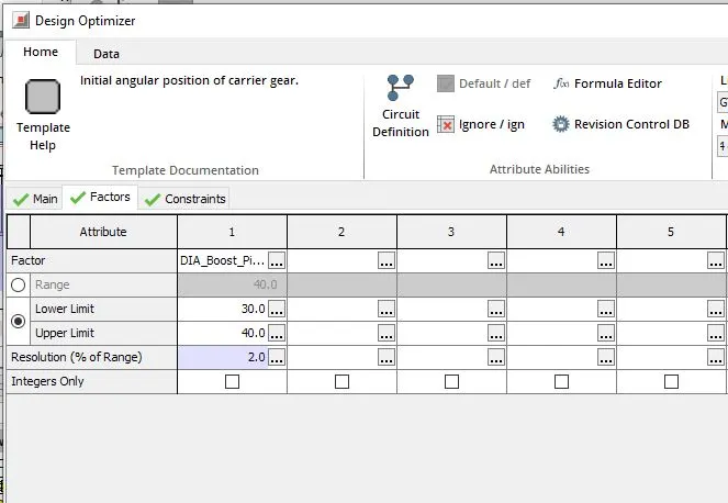
factors:
upper limit=40
lower limit=30
then click on run calibration and next
then click on run model and close
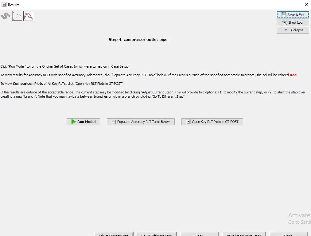
step5 window will be opened
select intake pipes and give step name as intake pipes
then click on simplify for accuracy
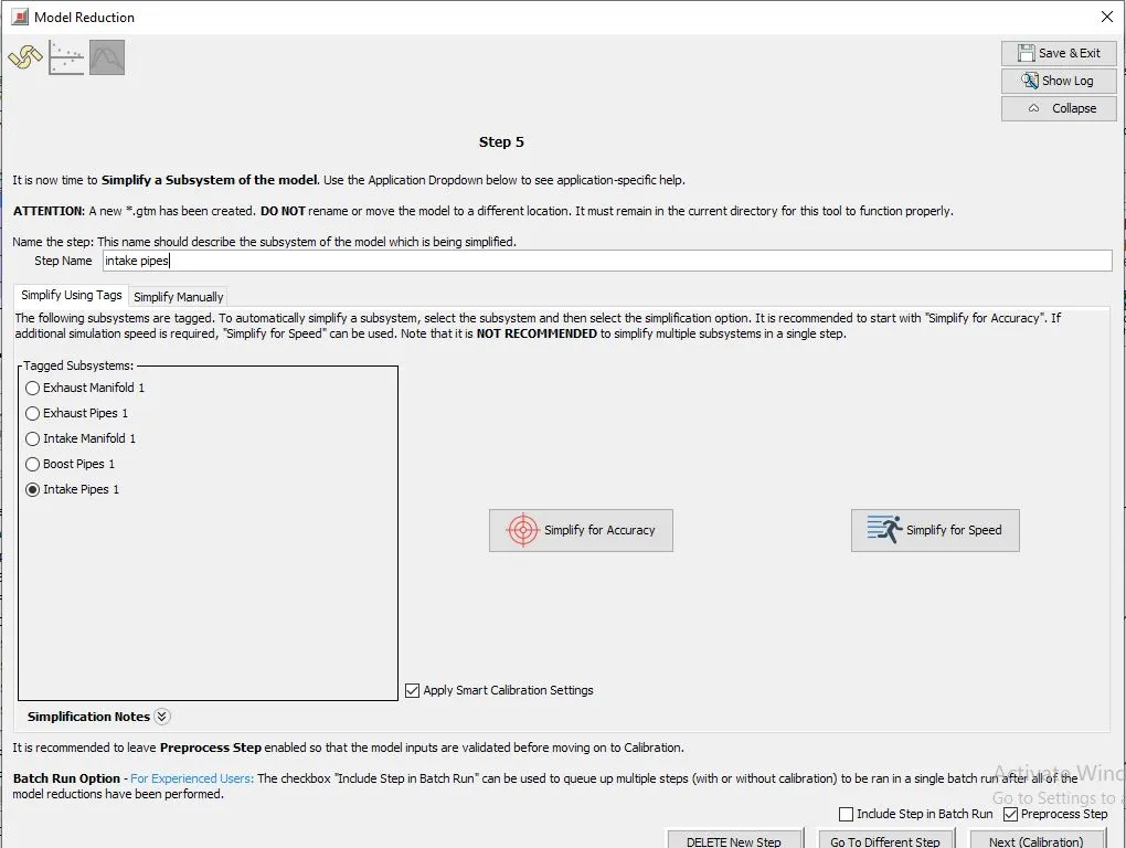
simplified model:
cases:
intake pipe diam is taken as a parameter
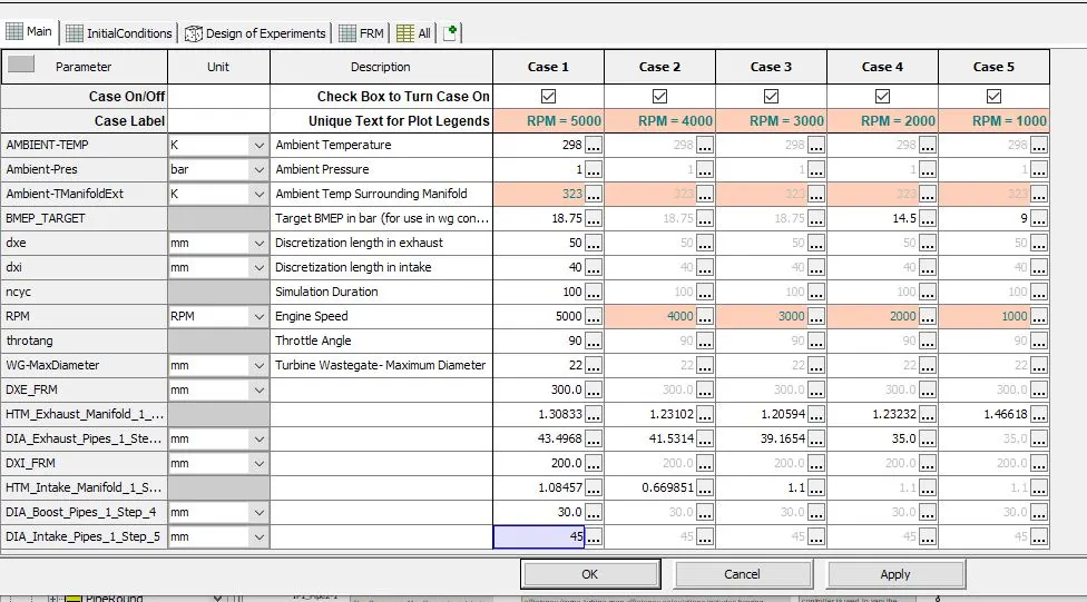
click on pipe round template and make sure all discretization length is DXI and DXE
only exhaust and intake
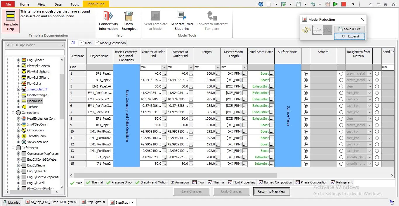
expand and click on next calibrate
this window is opened
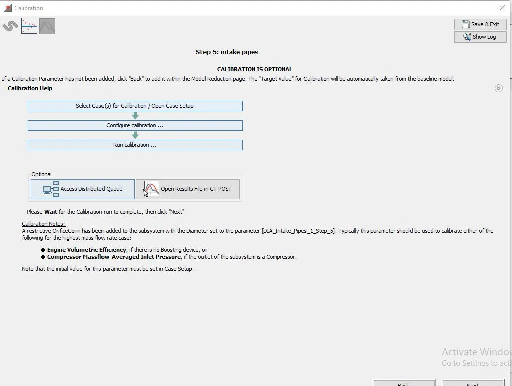
click on configure calibration:
design optimizer
response RLT = cmp-pia:compressor
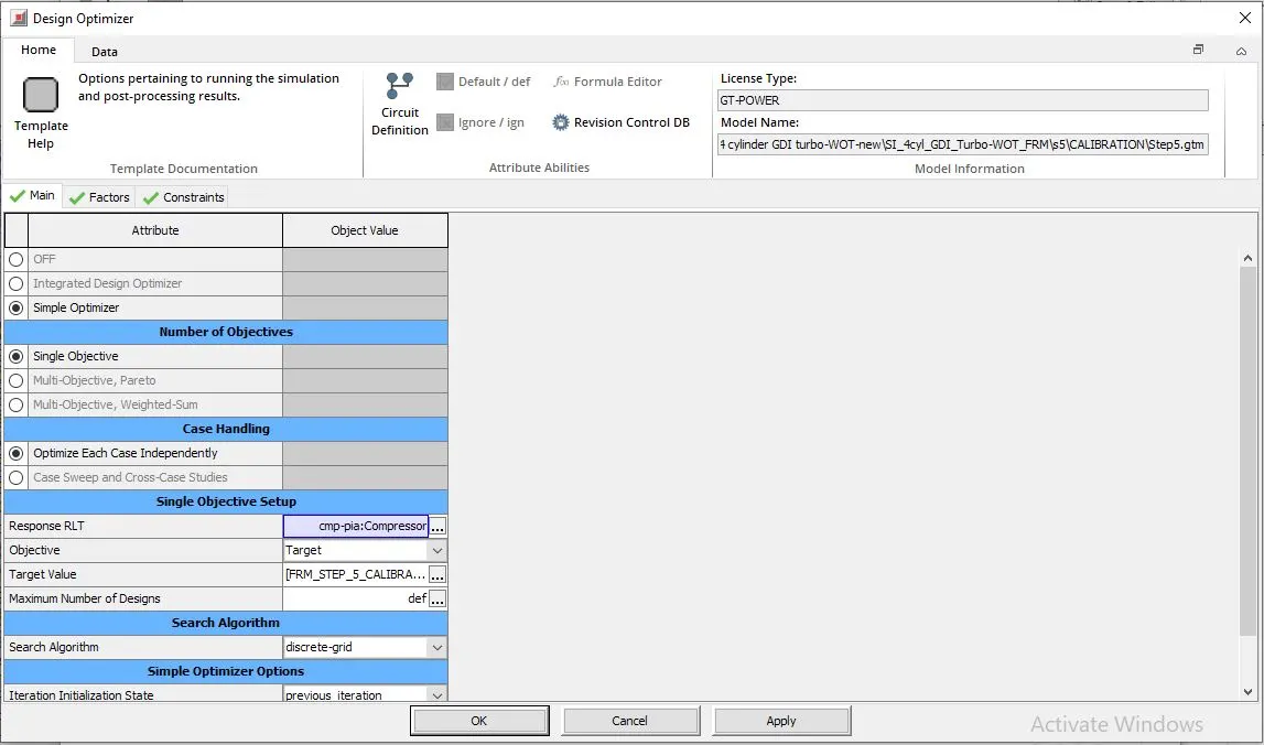
factors:
lower limit = 40
upper limit = 50
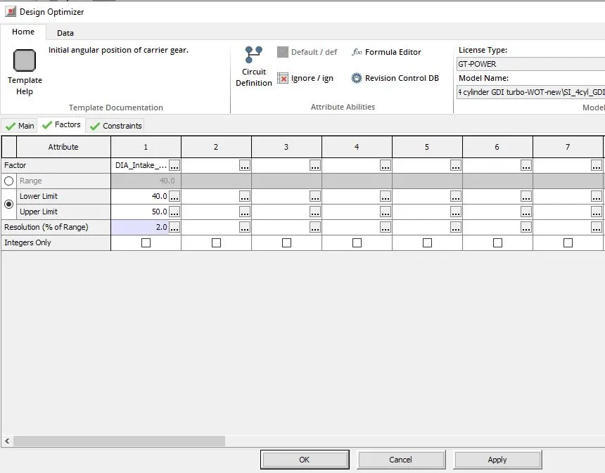
click on run calibration and next
in results window , click on Run model and finish
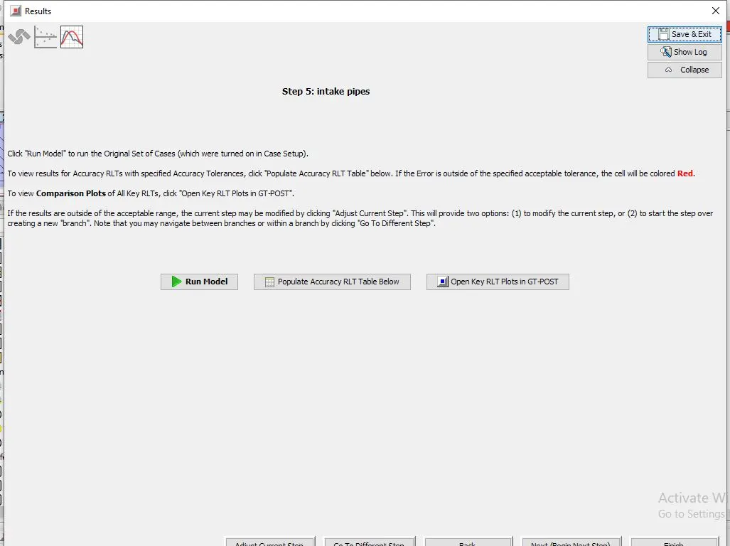
step6
give name as additional changes and click on simplify for speed
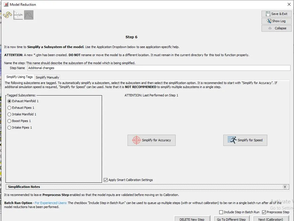
click on open case setup and check the cases setup
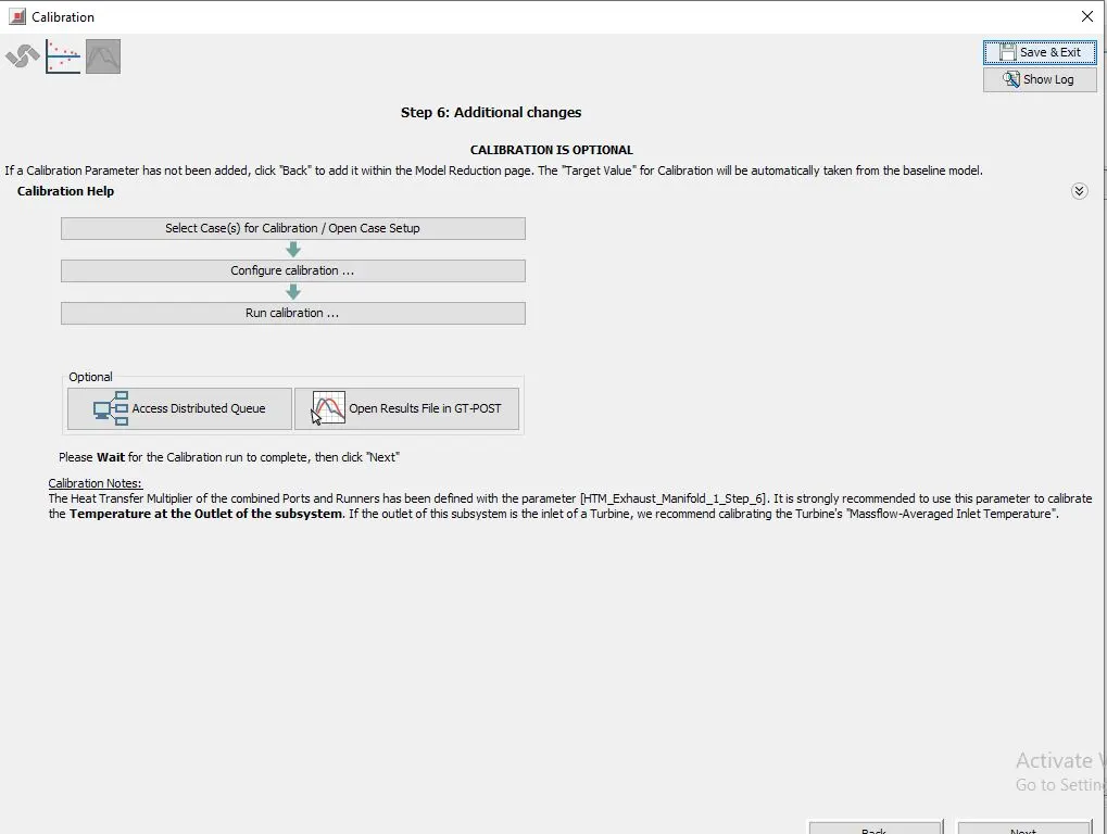
click on configure calibration
design optimizer:
Response RLT = trb-tia:Turbine
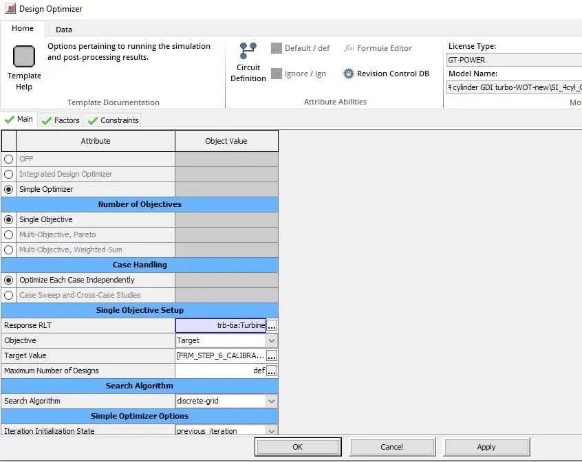
Factors:
lowerlimit = 0
upper limit=2
resolution = 1%
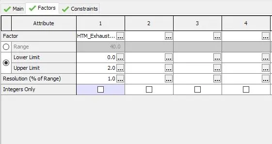
click on run calibration
in results window , click on Run model and finish
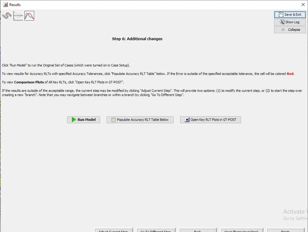
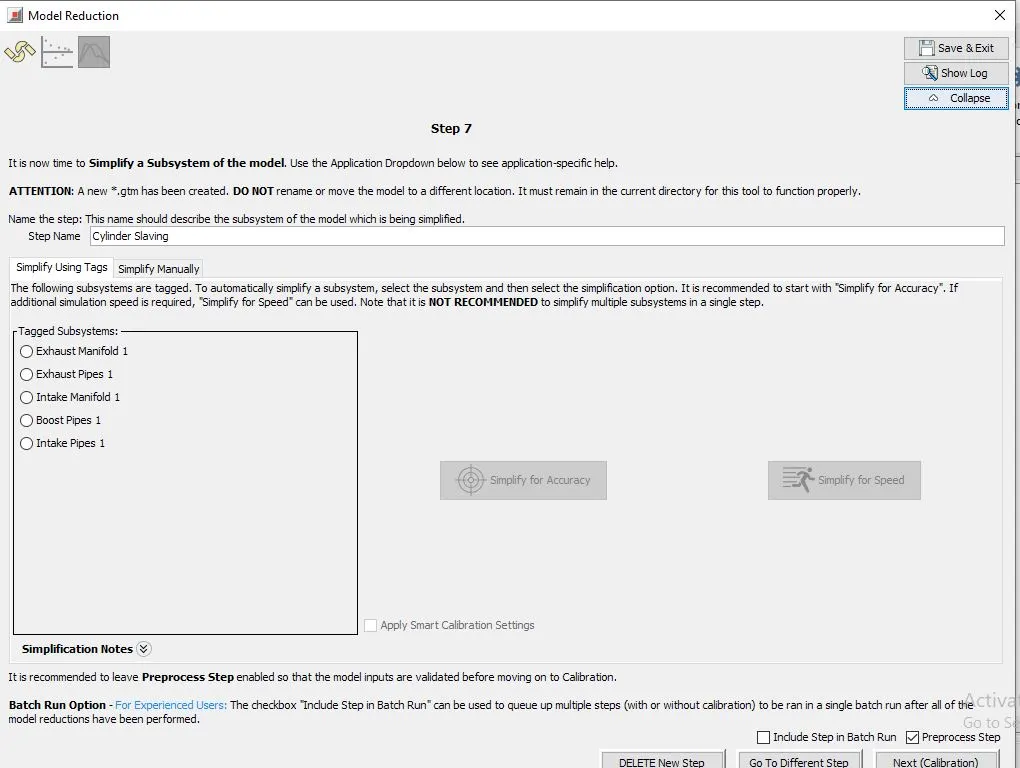
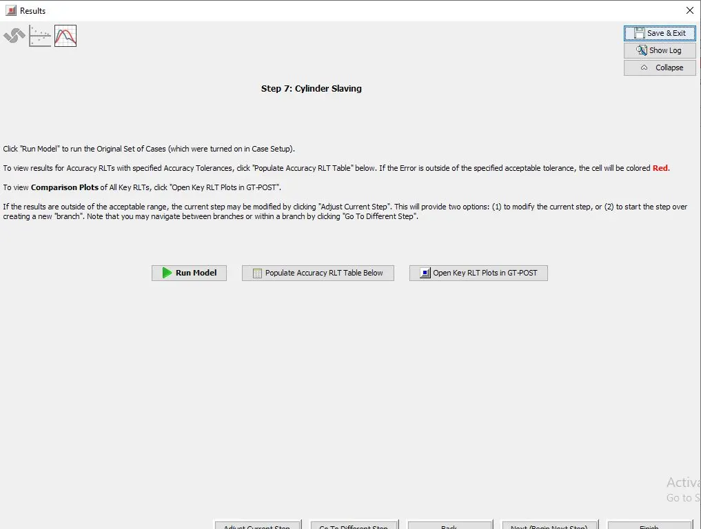
step7:
give name as cylinder slaving and click on collapse
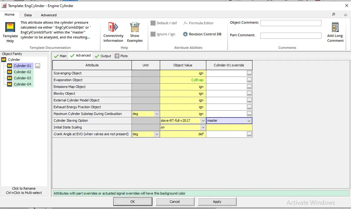
go to engine cylinder template
click on cylinder-01 and cylinder-01 overide
change cylinder slaving option to master in overide
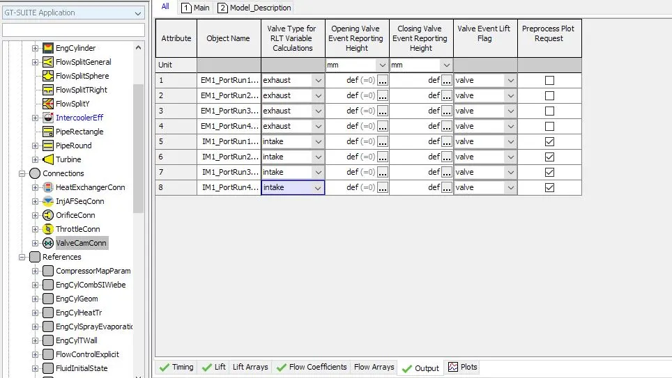
go to run setup
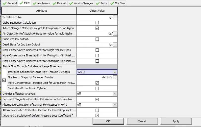
in flow , improved solution for large flow through cylinders as v2017
then click on expand and click on next calibrate
results window will be enabled , here click on run model and finish
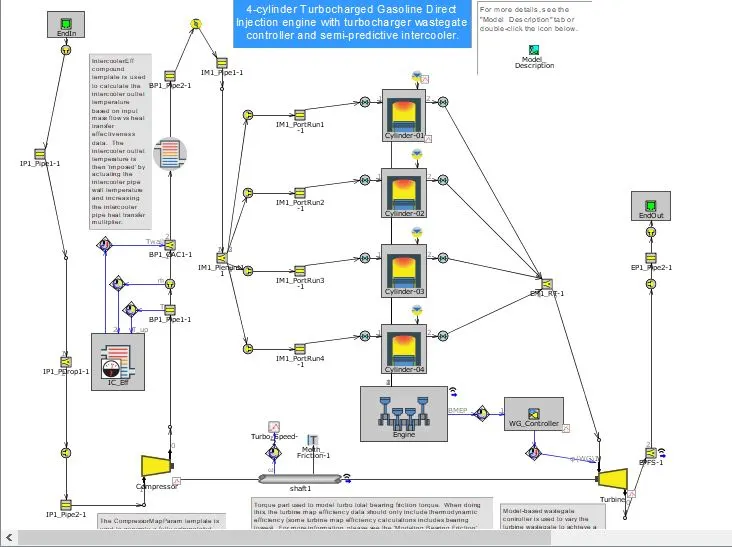
final main model:
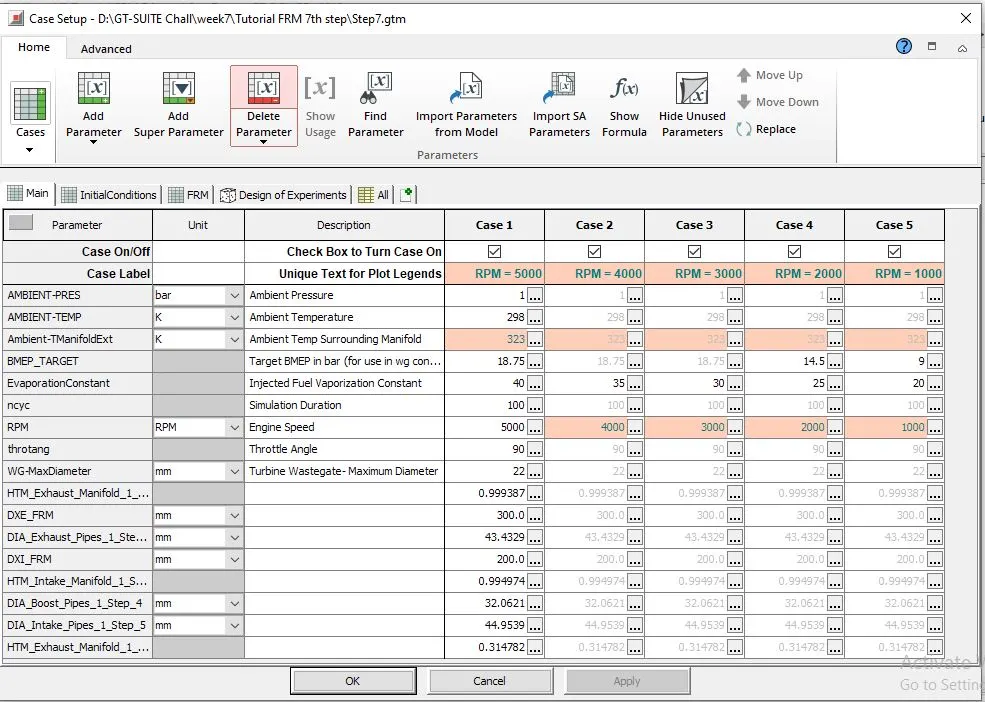
cases setup:
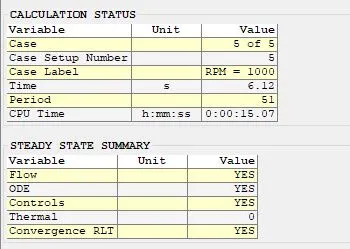
results:
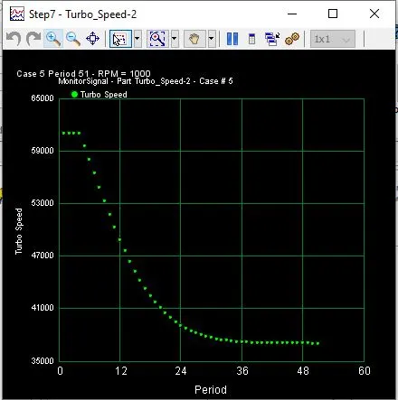
Turbine speed monitor:
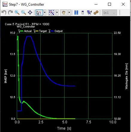
waste gate controller monitor: