Assignment 11
1. Tutorial- single cyl DI add case 2 with discretization length 0.1 mm for intake runner and compare with default case 1
-
- Parameters-Torque, BSFC, max cylinder pressure
- simulation time
2. Explore tutorial no 2 (GEM3D) - “Building intake manifold from STL model” (80 marks)
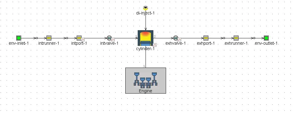
Single Cylinder DI :
main model:
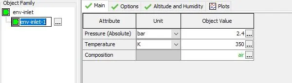
End environment inlet conditions:
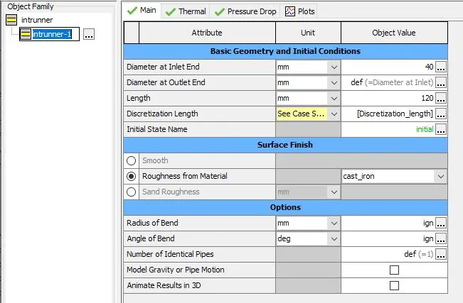
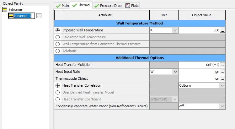
Intake runner:
main attributes
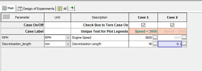
geomerty related details are to be mentioned , note here the discretization length is set as a parameter in case setup
Thermal attributes:
imposed wall temperature is 350k
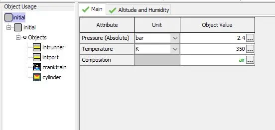
Initial state condition:
fluid initial state:
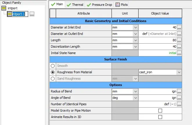
Intake port:
main attributes:
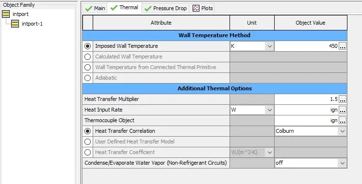
Thermal attributes:
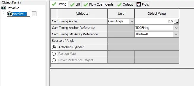
Intake valve:
Timing of intake valve:
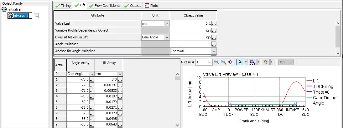
lift values:
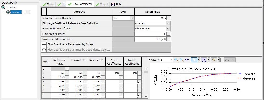
Flow coefficients:
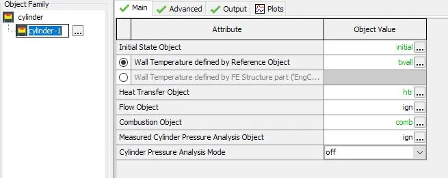
Cylinder main attributes:
Diesel injector:
main attributes:
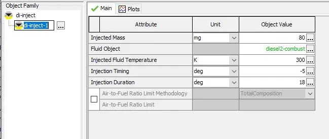
Engine craktrain:
Engine specifications:
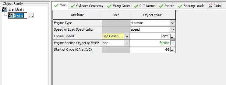
Engine geometry:
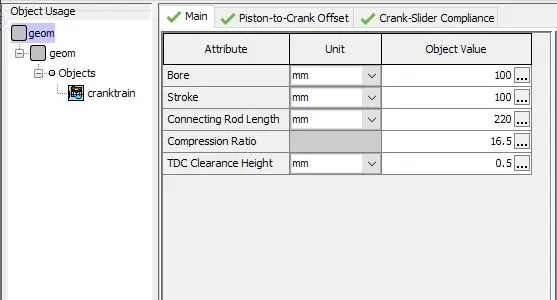
Ehaust valve:
Timings:
Lift values:
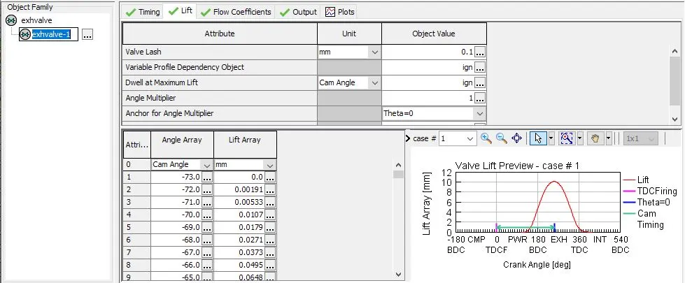
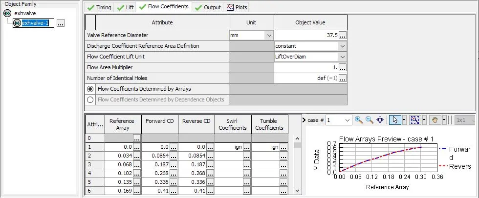
Flow coefficients:
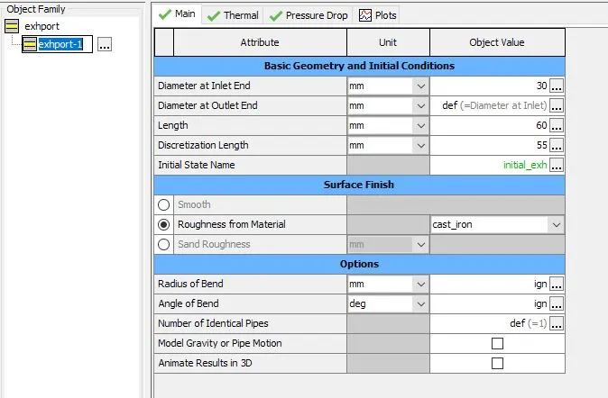
Ehaust port:
main attributes:
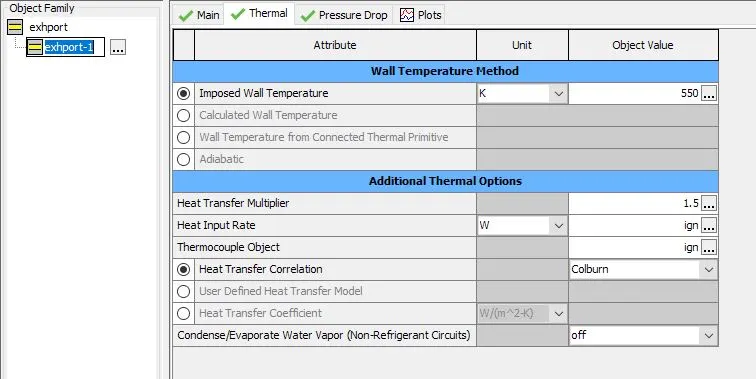
Thermal attributes:
imposed wall temperature is 550k
Exhaust runner:
main attributes:
geometry related details are mentioned
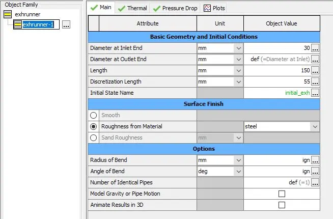
Exhaust runner:
Thermal attributes:
imposed wall temperature is to be 600k
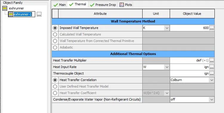
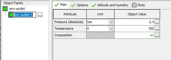
End environment:
outlet conditions:
Cases setup:
2 case are set, 1st case is default in which discretization length is 40mm ,for the second case the discretization length is 0.1mm
Run set up:
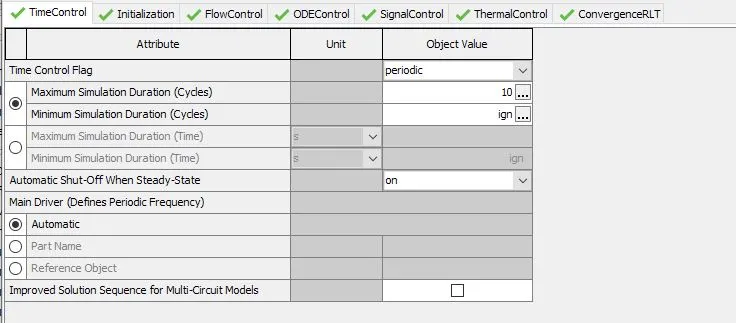
time control:
maximum simulation duration is 10 cycles
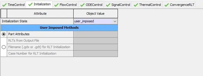
Initialization:
initialization state is user imposed
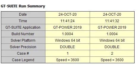
GT-POST:
GT-SUITE run summary details
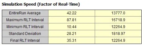
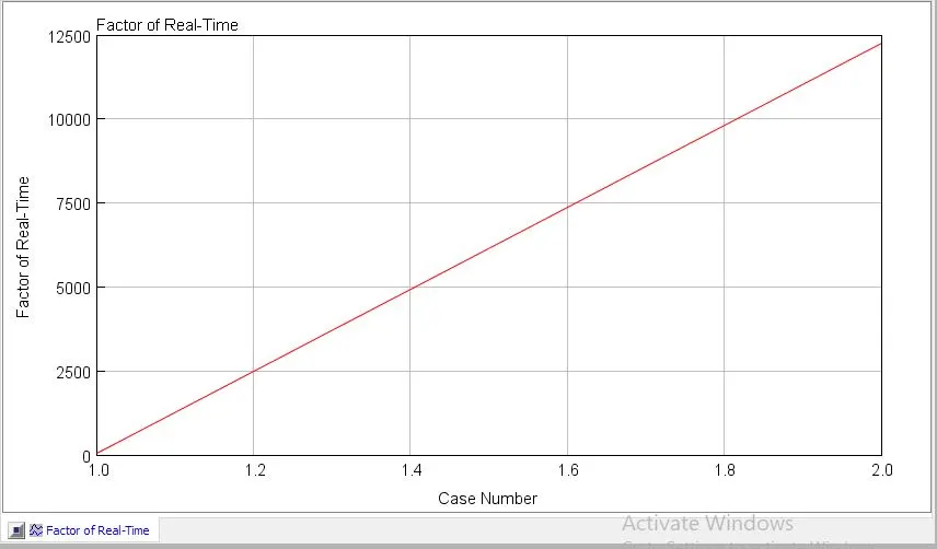
Simulation speed
it indicates the relative factor of time between the 2 cases to complete steady state
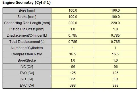
Engine geometry details:
bore=stroke=100mm
compression ratio=16.5
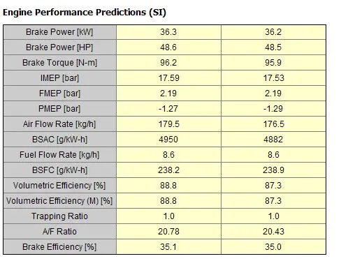
Engine performance predictions:
Brake power (1st case) = 36.3KW
Brake power(2nd case) = 36.2 kW
not much of a variation in brake power
Torque (1st case)=48.6 Nm
Torue(2nd case) = 48.5 Nm
Not much of a difference in torque as well
Air flow rate (1st case)=179.5 kg/h
Air flow rate(2nd case) = 176.5 kg/hr
almost 3 kg/hr is reduced at smaller or finer discretization length
BSFC(1st case) = 238.2 g/KW-h
BSFC( 2nd case) =238.9 g/KW-h
as air flow rate is increased hence BSFC also increases
there is no much of an increase , almost 0.29% increase
Fsctor of Real time:
2nd case almost took 12490 times more time
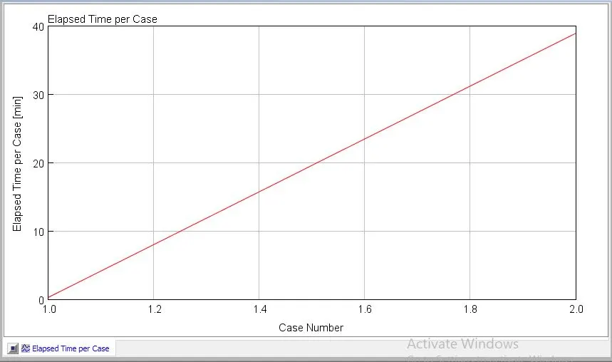
Elapsed time per case:
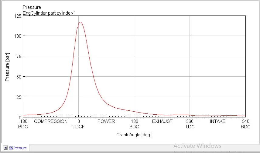
In cylinder pressure:
pressure vs Crank angle is given
(GEM3D) - “Building intake manifold from STL model” (80 marks)
Main model
Examples-Acoustics-non-linear(standard)-plenum.stl
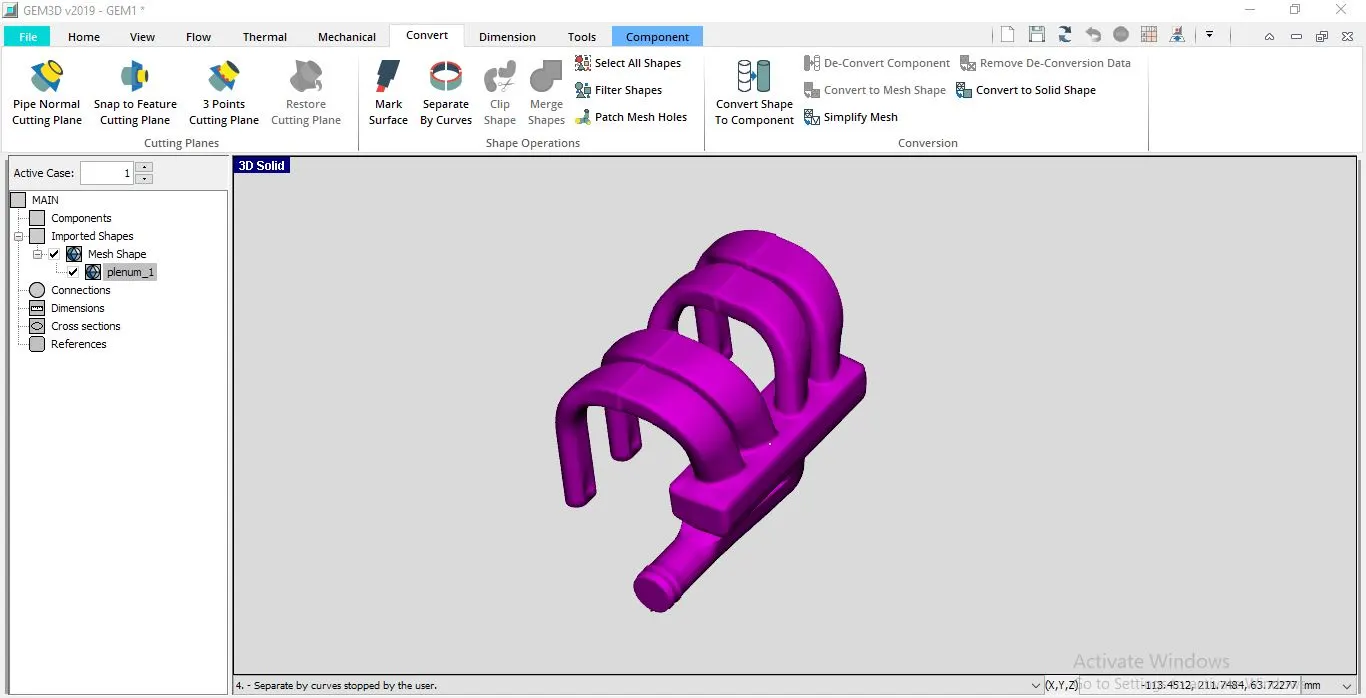
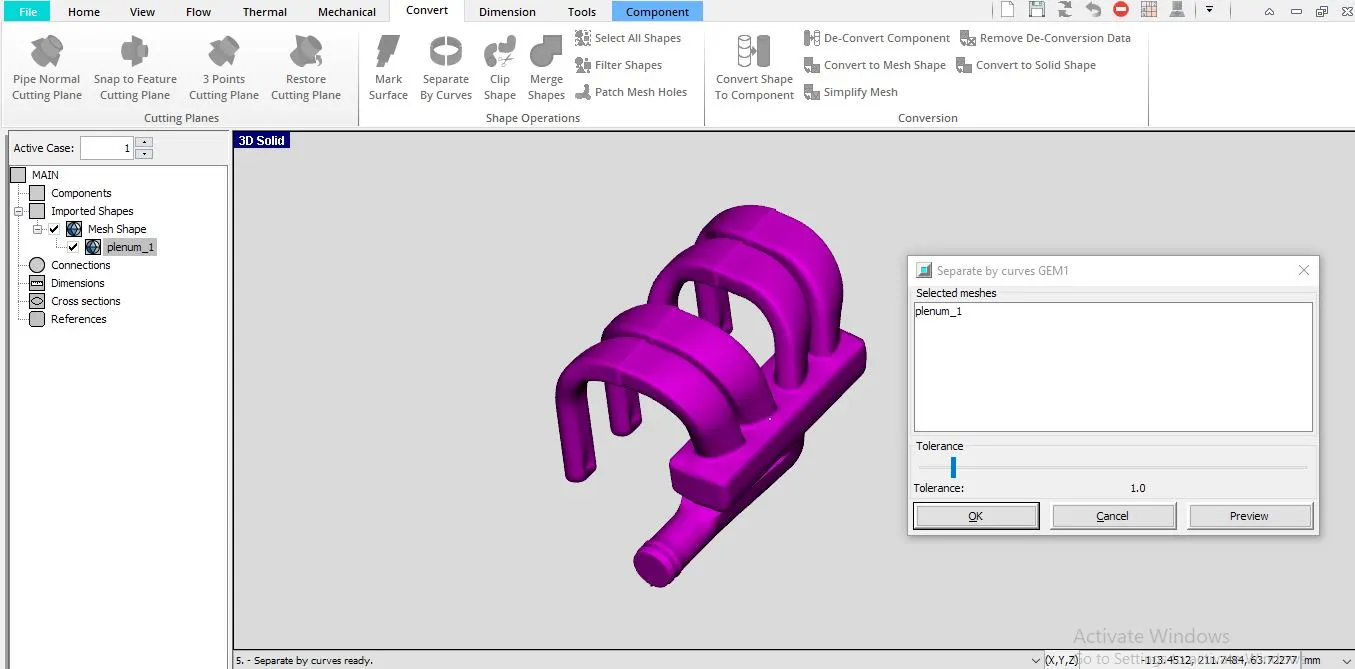
seperate by curves:
go to convert-select separate by curves and select the object
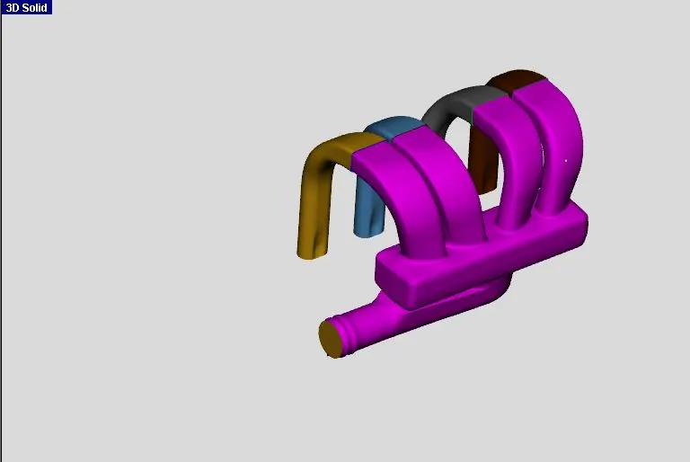
object spitted by curves:
Then go to convert - select 3 points cutting plane
choose the top face of the head as shown , adjust the position location and orientation are calculated and select clip
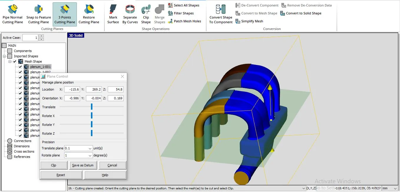
we can see the runner pipes detached from the head
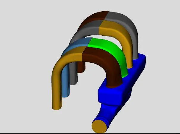
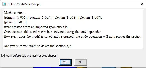
Then select the inlet face and outlet faces and delete them , this is to convert the fluid domain to 3D model object
It will look like this
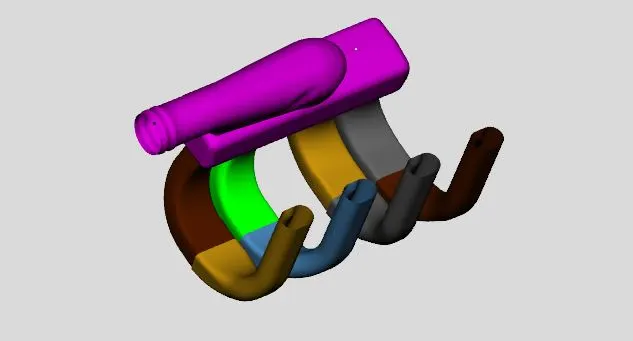
Now we need to convert the runners into suitable flow volumes
select the the first pipe coming from the runner head and right click and select convert shape to component
we can see something like below
select the pipe option and make sure the ports are numbered corrctly and click next
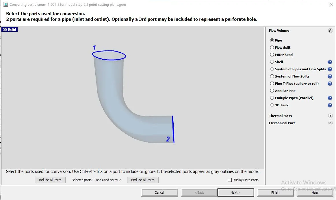
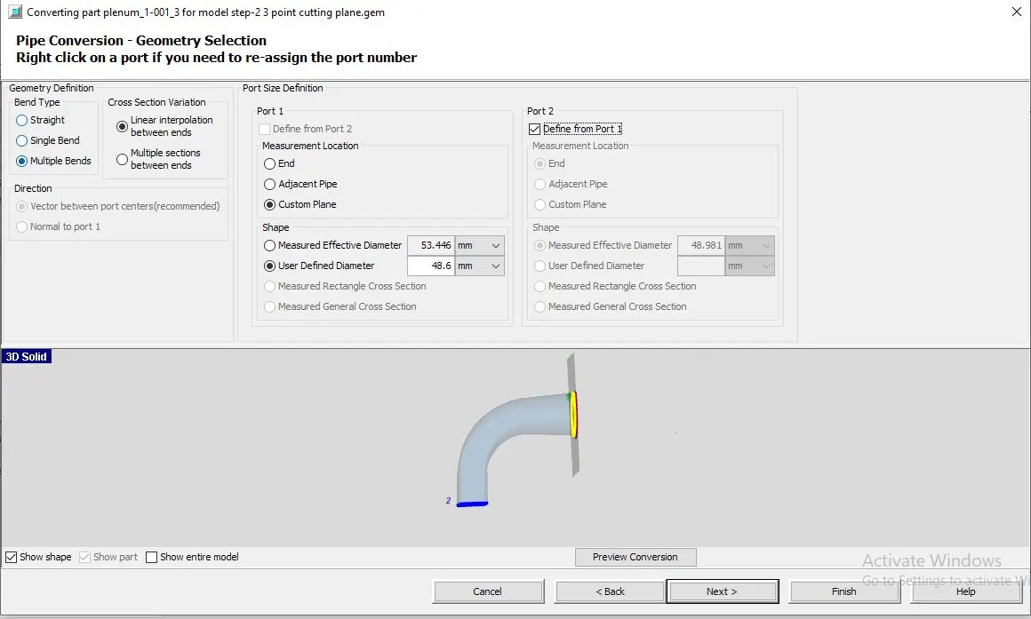
Select multiple bends
for port-1
shape- select user defined diameter and give value as 48.6mm
for port2
select define from port-1
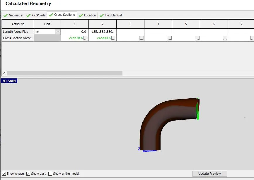
Calculated geomerty
here we can check the geomerty of the shape converted to pipe
we can check dimensions, its Cross section and coordinates
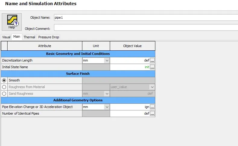
Name and simulation attributes
go to main:
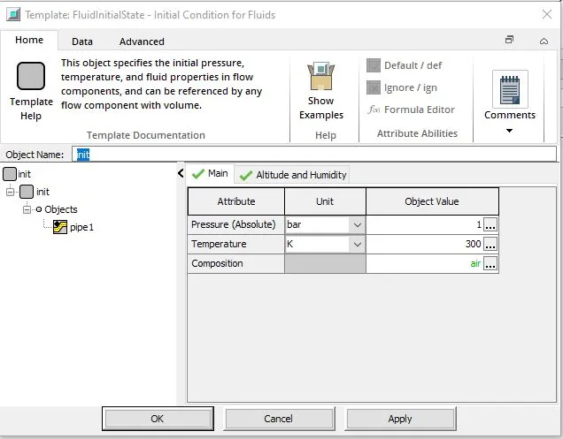
we need to define the initial state of the fluid
give P=1bar
Temperature = 300k
composition : click on the box on the right end and choose fluid mixture = air
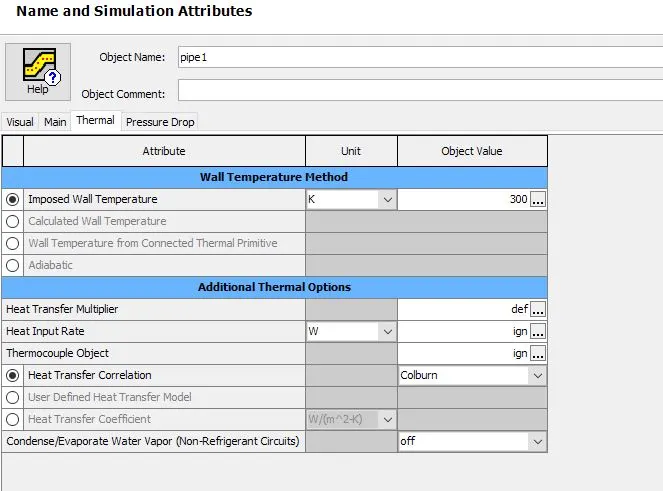
Thermal attributes:
imposed wall temperature give as 300k
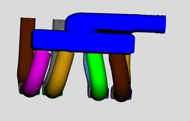
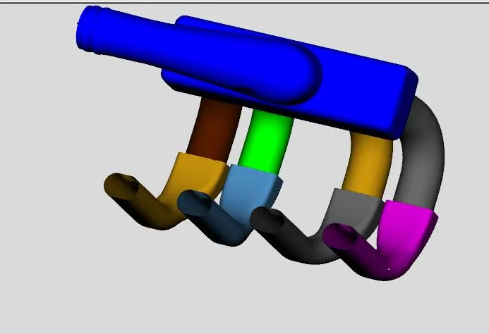
In the similar way convert all the shapes from the head into pipes ,
the result will look like this:
Now to convert the shape which is connected to the runner pipe(which was earlier converted)
folow the same procedure
choose pipe
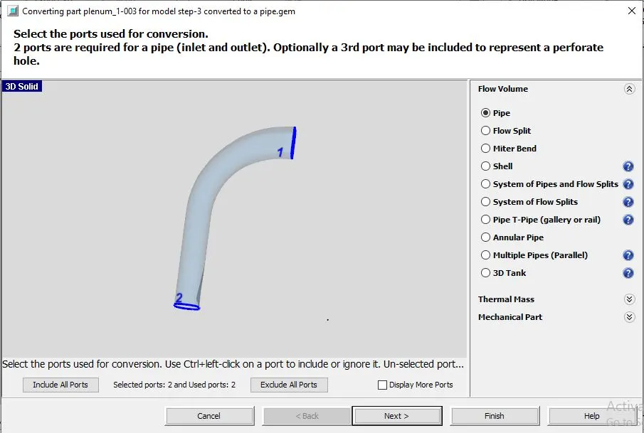
choose multiple bend
Port1:
user defined diameter = 51.5mm
port2:
user defined diameter = 38.24mm
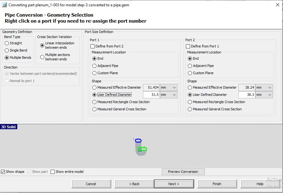
Follow the same procedure as for the earlier cases
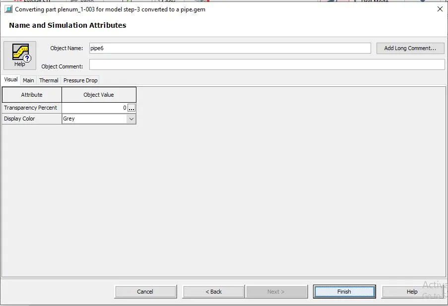
convert all the 4 into pipes,
the result will look like:
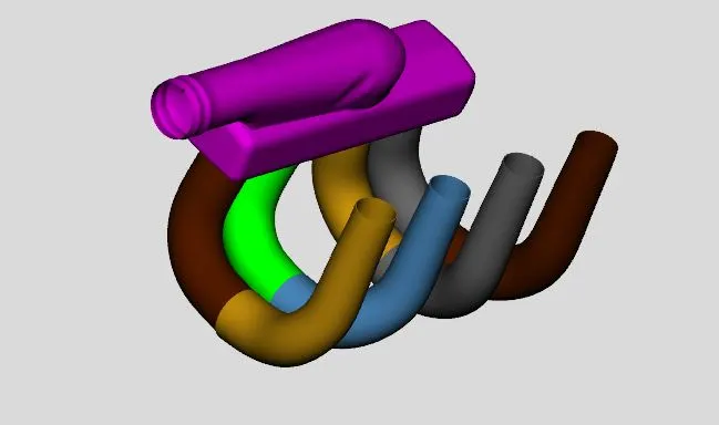
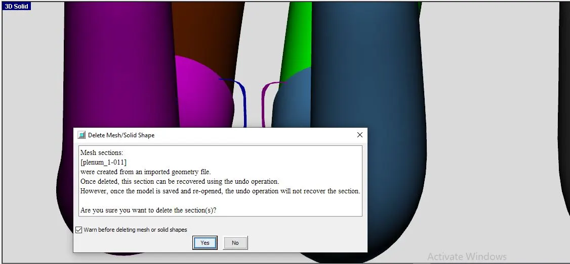
Delete any unwanted planes, delete the planes between the 2 pipes
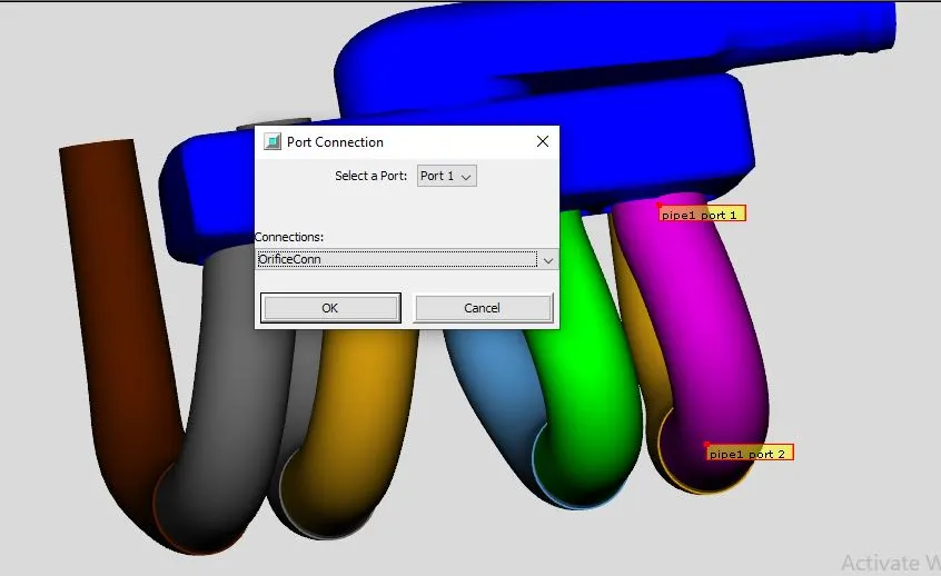
Adding orifice connections:
select the inlet pipe:
right click and select add connections:
choose : port1
connections : orifice conn
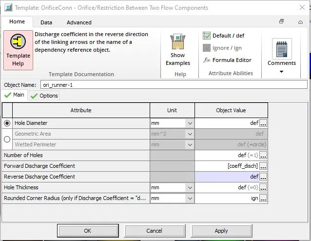
Orifice connection details:
here we need to give forward discharge coefficient as a parameter in run setup
Coeff_disch = 0.95
follow the same for the rest of the 3 pipes
Adding Assemble exchange:
select the outlet pipe:
right click and choose add connections
choose : port2
connections : GEMSubAssExtConn
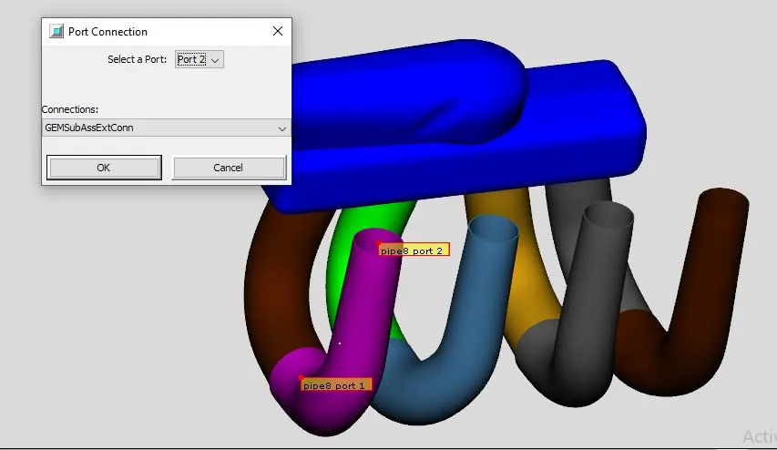
Port ID =1
flow direction = outtlet
follow the same procedure for the rest of the 3 pipes
Also follow the same procedure of the inlet head pipe , ther ethe flow direction = inlet
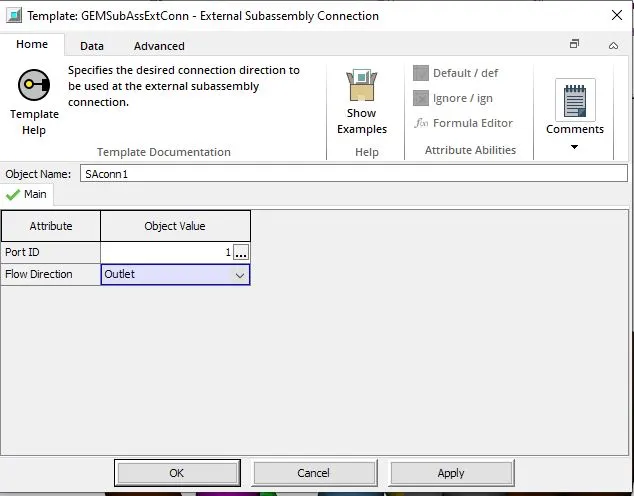
Now to split the upper head part:
convert- select pipe normal plane
using the slider we can move the normal plane ater required length i set up we can select clip
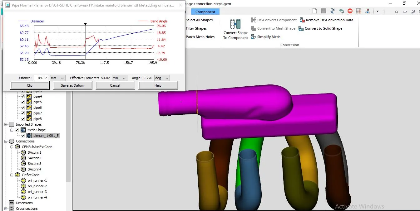
The pipe is clipped
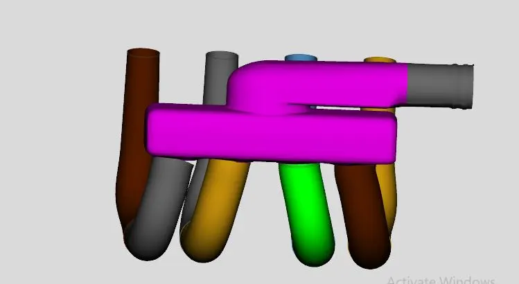
Follow the same procedure for the next halp of the inlet head upper part
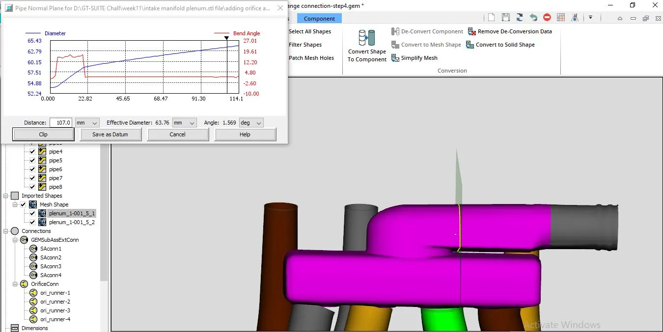
Now we have the upper head in 3 parts
Select the 1st part and convert into pipe:
follow the same procedures
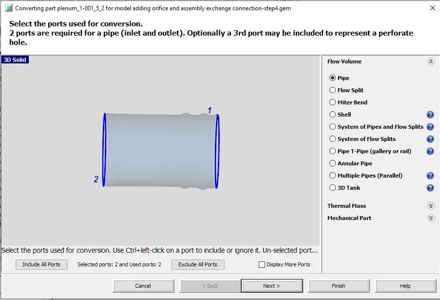
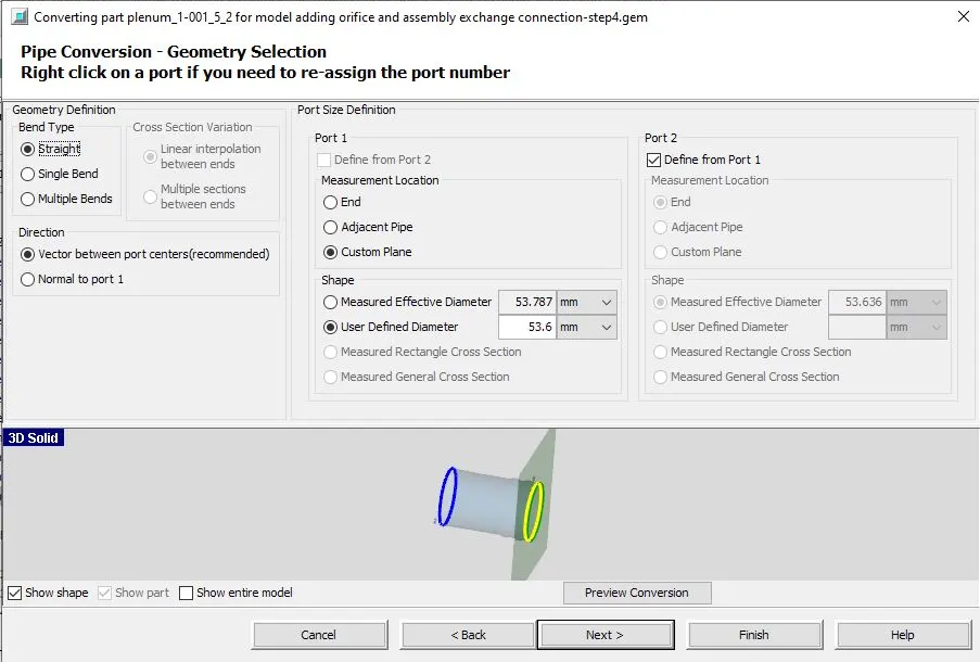
For th second part also we need to convert it into pipe
follow the same procedure ensure that port ID s are correct
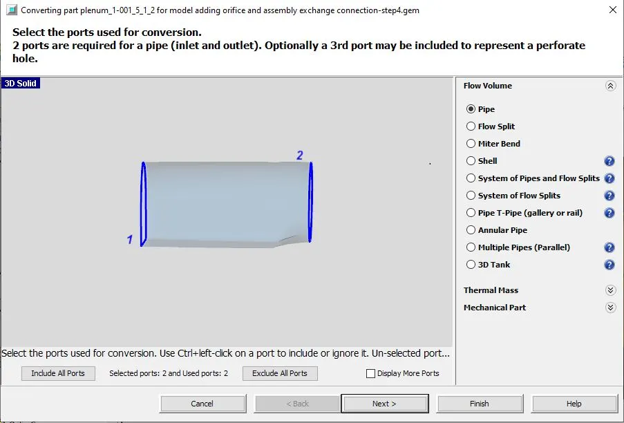
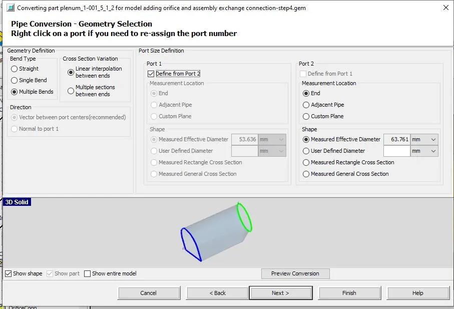
We can clearly see that 1st two parts of the upper head is converted to pipes
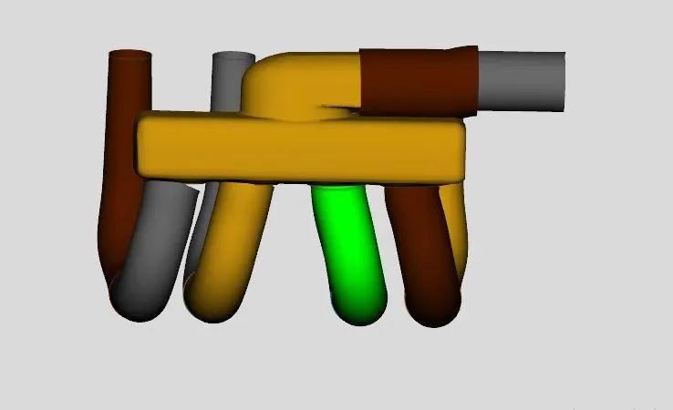
No we need to split the head into parts
select the upper head - go to convert- select-3 points cytting planes , select the required planes
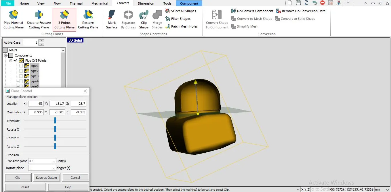
we can see that the head is split into 2 parts upper and lower
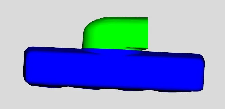
Converting the upper head part into flow split flow volume
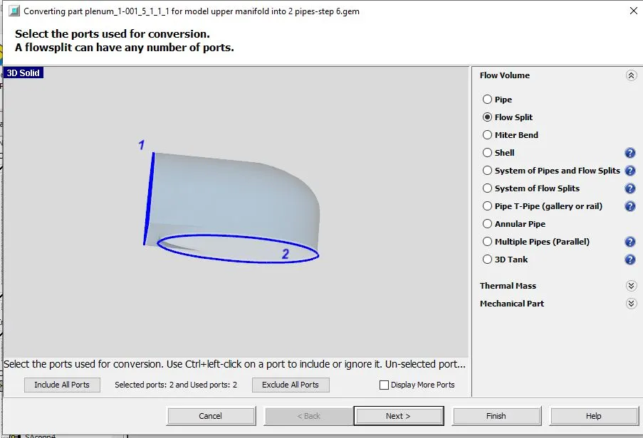
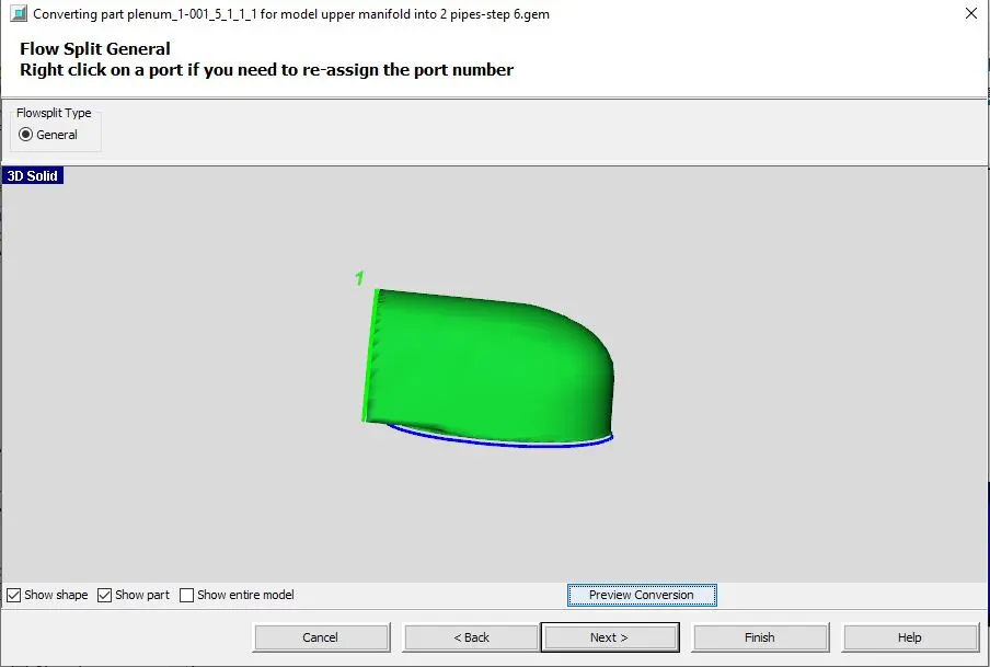
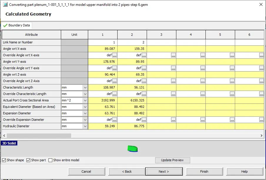
For the lower part of the head we need to again split it to smaller volumes
select the body and go to convert- select 3 point cutting plane
choose the left face as shown and select the required length then select clip.
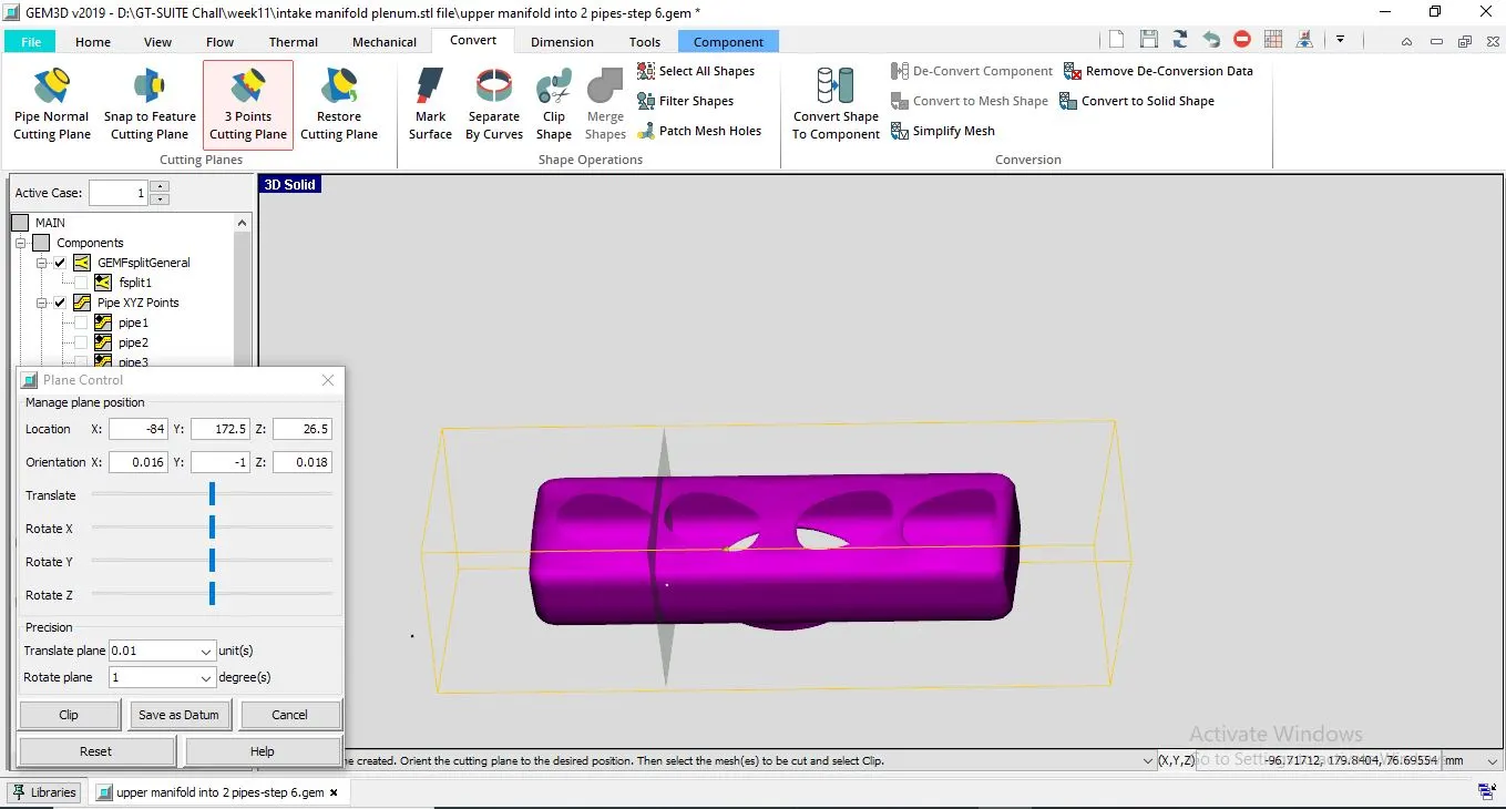 \
\
follow the same procedure for the other end
the split volumes is as follows
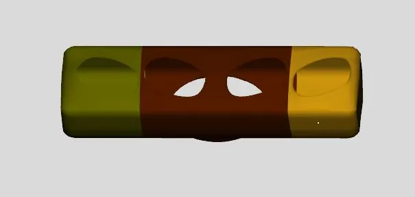
Now to convert the split parts into flow volume
Choose the part-right click- select-convert part to component
flow volume = flow split
then follow the other steps as for the previous case
The boundary data for the flow split is as follows:
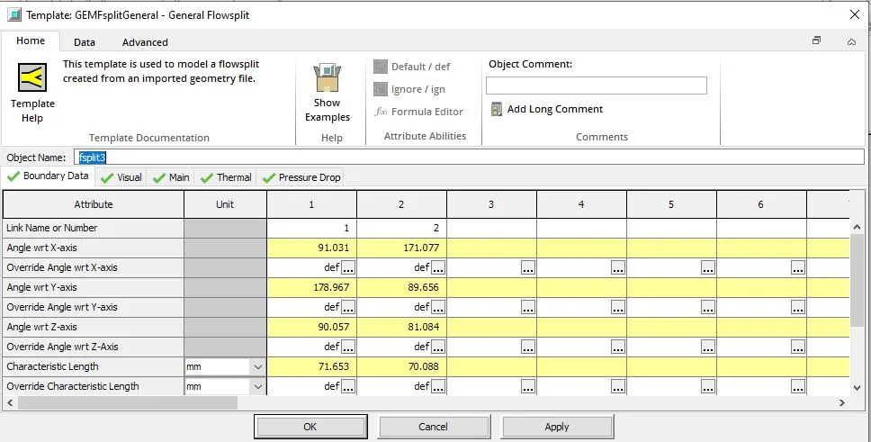
Main attributes:
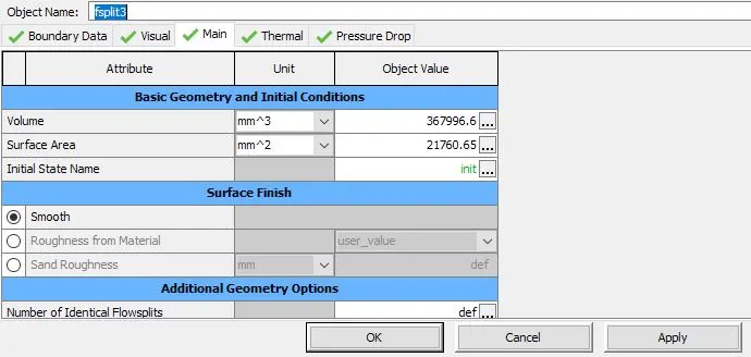
follow the same procedure for the right end part as well
Now for the central part,
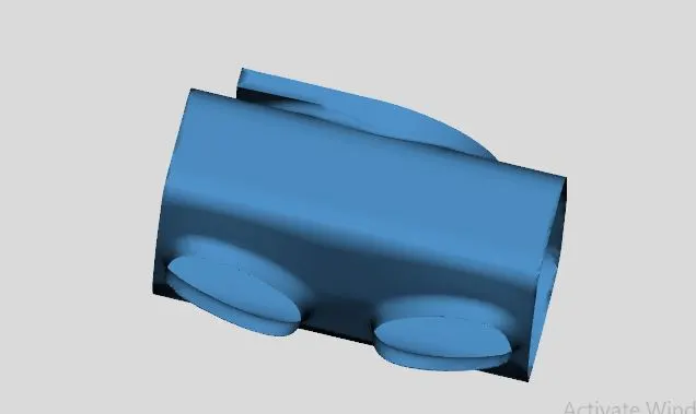
convert the central part into flow split 4
following the same procedure as for the previous cases
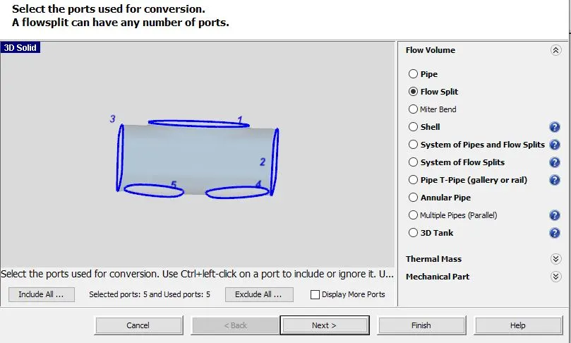
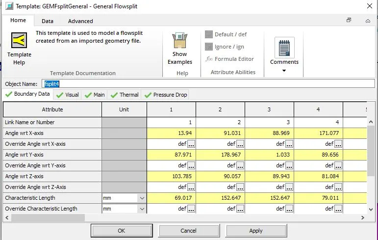
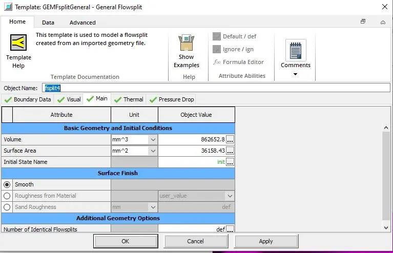
once done , the pipes will not be connected to each other , for this we need to go to flow- select connections- flow connectors it will show all the places where the connections need to be given , there will be 2 planes and spanner shape cursor , we need to click the planes which needs to attached by placing spanner over the planes and clicking them , once two planes are clicked , these planes will coincide thus connecting the 2 shapes.
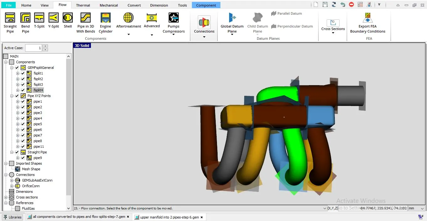
Click on Eport GT Model
check for the discretization length , default is 40mm which can be changed
then click on discretize
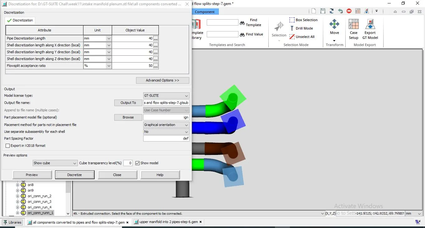
Discretization is finished and a message will be shown:
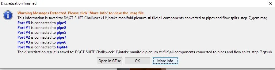
Open GT-SUITE:
the intake manifold discretized diagram will be shown
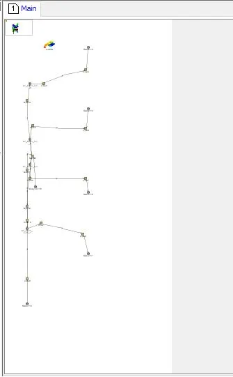
Rearranging the same diagram :
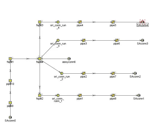
this is the final Intake manifold model