Crash-worthiness Pole Side Crash Test on the BIW (Body in White) Structure using HYPER-MESH and RADIOSS
Aim:
To perform computer model CRASH-WORTHINESS Crash test for Side Pole Impact Analysis on the BIW Structure of Automotive Vehicle due to Side Pole Impact using HYPER-MESH & RADIOSS.
Objective:
The objective is to analyze the BIW (Body in White) with the side pole crash analysis and check for the impact of this side crash on the BIW structure in the high-velocity crash on the pole.
Study of the forces received energy generated and displacement on the various cross-sections of the BIW and study of the various energy plots after running the simulation.
Abstract:
- Check unit system and either follow [Mg mm s] or [Kg mm ms].
- Create an appropriate interface, friction 0.2, and recommended parameters.
- Make sure of no penetration and intersections.
- Create a rigid wall with friction 0.1 as per the reference model.
- Compare the model weight with the reference model and use added masses to reach the target weight of 700kg while getting CG about the required range.
- Initial velocity as shown in the picture.
- Use a model checker to ensure good quality.
- Timestep :0.5 to 0.1 microseconds.
- Run 80ms.
Introduction:
What is a crash test?
A crash test is a form of destructive testing usually performed to ensure safe design standards in crashworthiness and crash compatibility for various modes of transportation or related systems and components.
Types of Crash Test:
- Frontal-impact tests: Front Impact test is what most people initially think of when asked about a crash test. Vehicles usually impact a solid concrete wall at a specified speed, but these can also be vehicles impacting vehicle tests. SUVs have been singled out in these tests for a while, due to the high ride-height that they often have.
- Moderate Overlap tests: Moderate Overlap tests in which only part of the front of the car impacts with a barrier (vehicle). These are important, as impact forces (approximately) remain the same as with a frontal impact test, but a smaller fraction of the car is required to absorb all of the force.
- Small Overlap tests: Small Overlap tests this is where only a small portion of the car's structure strikes an object such as a pole or a tree, or if a car were to clip another car. This is the most demanding test because it loads the most force onto the structure of the car at any given speed. These are usually conducted at 15-20% of the front vehicle structure.
- Side-impact tests: Side Impact test these forms of accidents have a very significant likelihood of fatality, as cars do not have a significant crumple zone to absorb the impact forces before an occupant is injured.
- Pole-impact tests: A difficult test that places a large amount of force on a small proportion of the side of the vehicle.
- Roll-over tests: A rollover test tests a car's ability (specifically the pillars holding the roof) to support itself in a dynamic impact. More recently, dynamic rollover tests have been proposed in place of static crush testing (video).
- Roadside hardware crash tests: Roadside hardware crash test is used to ensure crash barriers and crash cushions will protect vehicle occupants from roadside hazards, and also ensure that guard rails, signposts, light poles, and similar appurtenances do not pose an undue hazard to vehicle occupants.
- Old versus new: Often an old and big car against a small and new car, or two different generations of the same car model. These tests are performed to show the advancements in crashworthiness.
- Computer model: Because of the cost of full-scale crash tests, engineers often run many simulated crash tests using computer models to refine their vehicle or barrier designs before conducting live tests.
- Sled testing: A cost-effective way of testing components such as airbags and seat belts is conducting sled crash testing. The two most common types of sled systems are reverse-firing sleds that are fired from a standstill, and decelerating sleds which are accelerated from a starting point and stopped in the crash area with a hydraulic ram. It can also be used to evaluate the whiplash protection of a vehicle's seat.
But for our study, we will just see the little combination of Pole and Side Impact Test of the BIW Structure. For this, we have the BIW structure available as below.
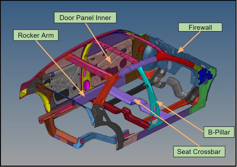
fig - BIW Structure
Model Setting:
Firstly we import the model to the hyper mesh window as below,
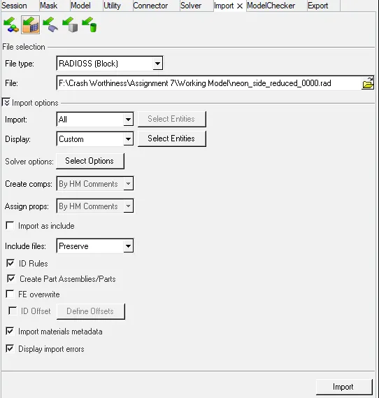
fig - Import the model
The downloaded neon reduced model is imported from the folder where it was saved.
Step I - Check the unit System
After importing the geometry we go to check the unit system used in the rad file. For this, we open the 0000.rad file in the notepad and observe the unit system over there. The purpose of checking this unit system is important to check because if the unit consistency is different than expected the whole calculation will go wrong at the end of the project.
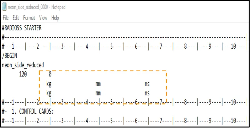
fig - Unit System
From the above image, we can see that the unit system used for this model is Kg-mm-ms which is always preferable for the industry.
Step II - Create an appropriate interface, friction 0.2, and recommended parameters.
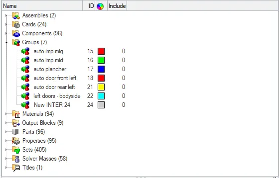
fig - Unwanted Interface
The unwanted interface cards which were present in the previous model are deleted and a new card is created.
The interface card is created using Type 7 contact with the recommended properties as below and also this time friction factor is added to give some friction between the slave and master node.
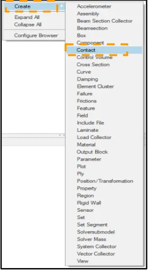
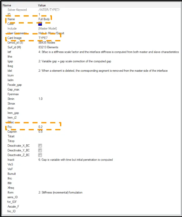
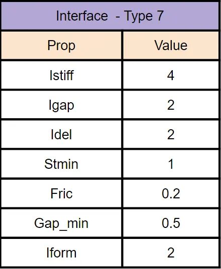
fig - Creating a New Interface Card
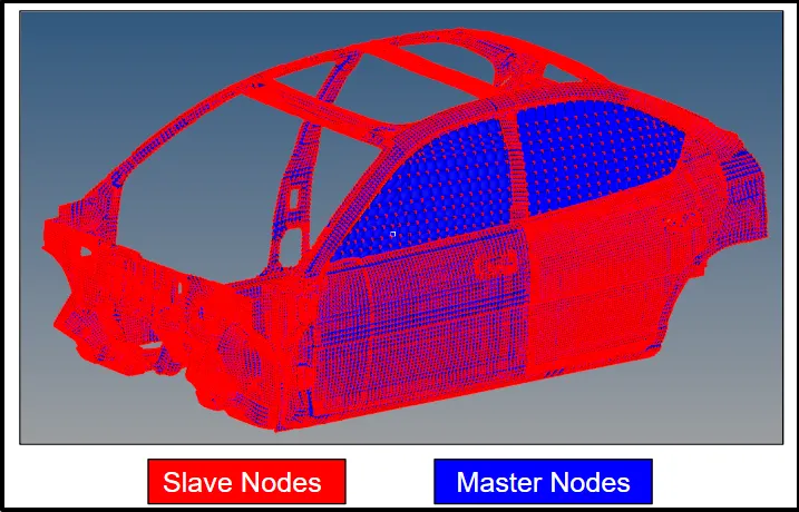
fig - Slave Nodes and Master Nodes
Step III - Make sure of no penetration and intersections.
After creating the interface card we check if there are an intersection and penetration present in the model.
Penetration and Intersection Check
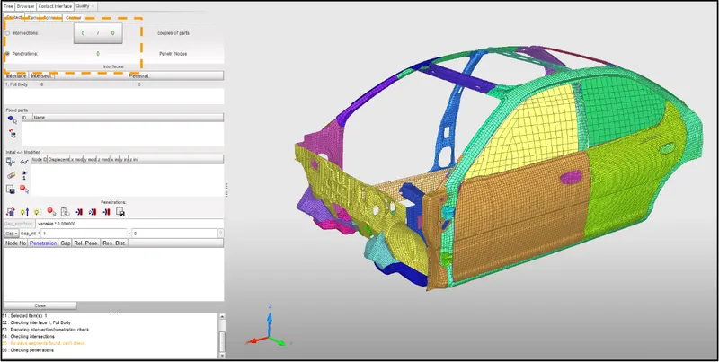
fig- Intersection and Penetration Check
Before going ahead to the next step we have to check for whether there is any penetration or intersection present inside the model. This is pretty important because if there is any penetration observe we have to recheck for the interface parameters again and make necessary changes accordingly. For our case as shown above there is no intersection and penetration so we have a green signal to go ahead with the next step.
Step IV - Create a rigid wall with friction 0.1.
Now there is a need to create a rigid wall on which the vehicle is going to impact with some initial velocity. To create the rigid wall there is an option in the model browser to create the rigid wall. By right-clicking in the model browser, we will get the option to create the RWALL with the below parameters and the representation of the rigid wall is shown below,
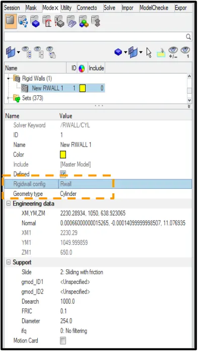
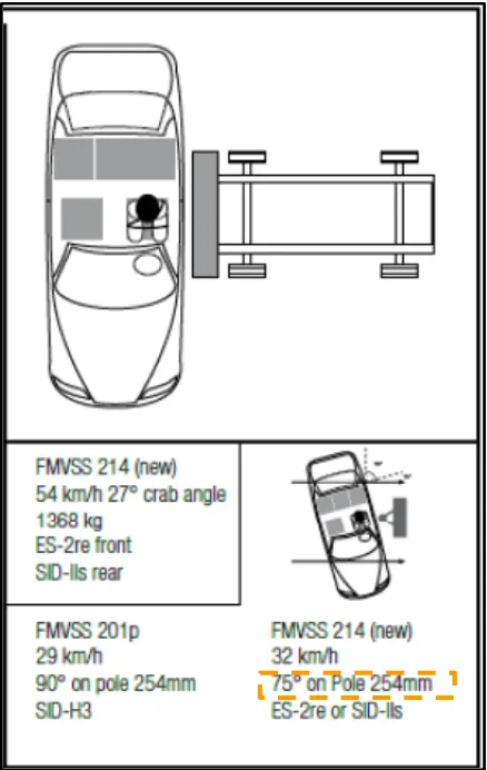
fig - Rigid Wall Parameters
The cylindrical wall is created using the FMVSS 214 guidelines as shown in the above figure. The diameter of the poles is 254 mm.
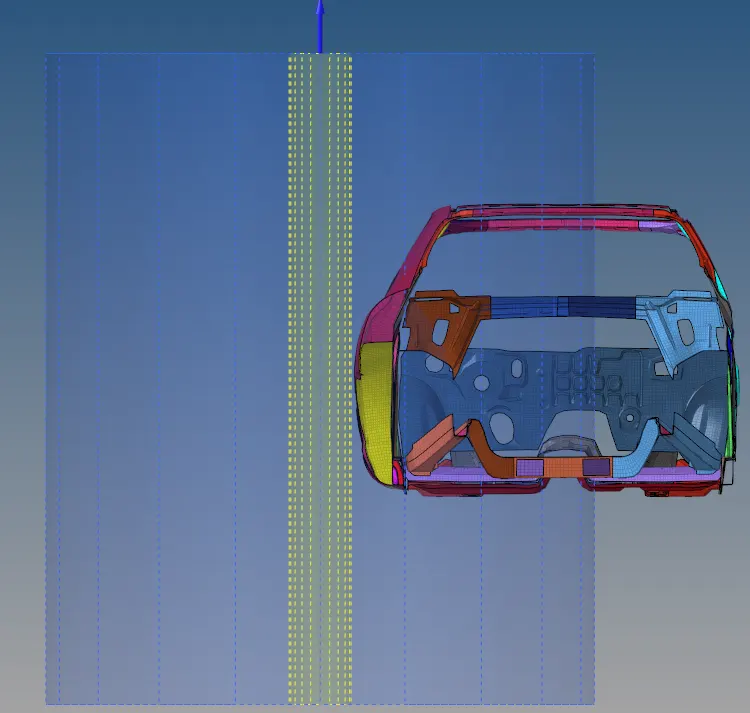
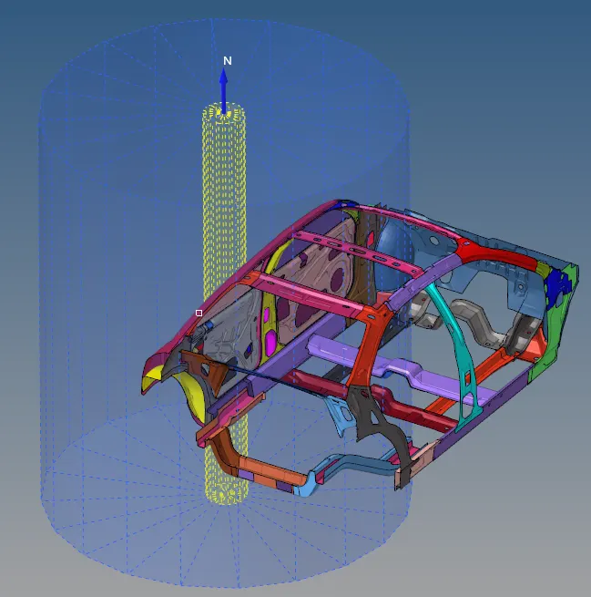
fig - Cylindrical Rigid Wall
Here we can see that the geometry type used is Cylindrical Wall so that the sufficient area of impact will be available to make the impact. The coordinates of the rigid wall are created using 2 nodes on the outer door and keeping the rigid wall a little away from the side doors to avoid the penetration of the wall in the vehicle. This wall is created concerning the normal direction in the Y-axis and a positive direction. To make it sliding friction wall sliding friction with 0.1 is introduced in the rigid wall with Dsearch distance of 1000. This Dsearch distance will search the slave node till this region in the model.
In the above image, we can see that the yellow color dotted line represents the cylindrical rigid wall with a diameter as described below, and the blue color transparent area is the Dsearch for finding the slave nodes in this region.
Step V - Maintain the CG (Center of Gravity) about the required range
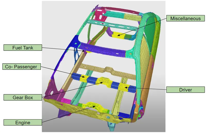
fig - Added Mass at Various Location

Here we can see in the reduced vehicle model that the weight of the model is around 166 Kg approx so the CG (Center of Gravity) is not maintained properly and that of in Full Vehicle model is 1200 Kg approx so to maintain the vehicle stability during the test we have to increase the weight of the vehicle with the help of added masses for Driver, Co-Passenger, Gear Box, Engine, Fuel Tank and considering some miscellaneous weight.
So for our instance, we added the mass at the below-mentioned location to maintain the CG to the required location,
Co-Passenger - 100 Kg
Driver - 100 Kg
Engine - 150 Kg
Gear Box - 100 Kg
Fuel Tank - 59 Kg
Miscellaneous - 25 Kg in Rear (This weight can be considered as a spare tire, mechanical tools, etc.)
As per the standard rule, the center of gravity of any model is to lie near the driver seat so by adding the added mass to the model we had achieved our CG point near the driver seat as we can see above.
Step VI - Assign Initial Velocity to full BIW Structure
To make the impact on the cylindrical rigid wall we have to introduce some initial velocity to our model. So to do this in the solver we can introduce the initial velocity as shown below,
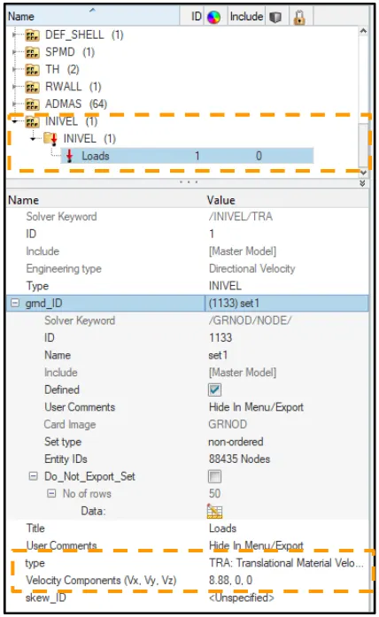
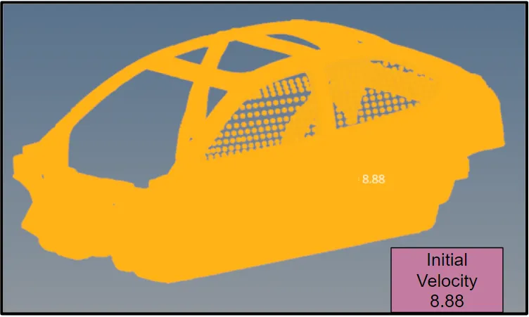
fig - Initial Velocity
The initial velocity reference is taken from FMVSS 214 guidelines which say that the vehicle velocity while impacting the pole should be 32 Kmph. All sets of nodes in the model have been assigned with the initial velocity of 8.88 mm/ms (19.88 mph / 32 Kmph) and the Translational velocity is assigned as a type.
Step VII - Assign Time Step to control the model
For this, we add the DT card to the solver to introduce the time step with the time scale value of 0.5. This is used to define the time step control during the computation.
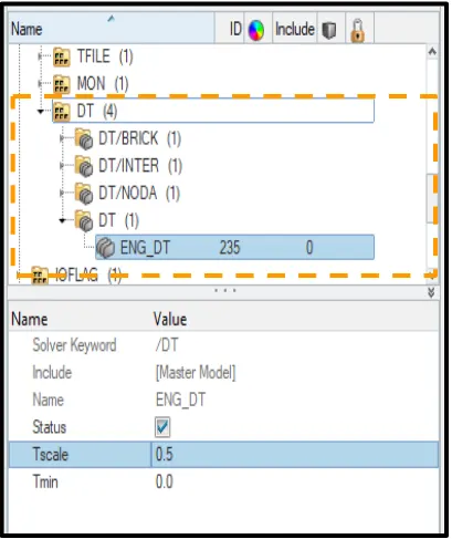
fig - Time Step Definition
Step VIII - Assign Engine Run Time for Simulation
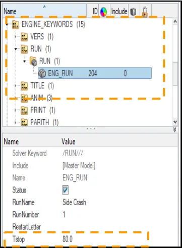
fig - Simulation Run Time
The simulation time is set to be run for 80 sec.
Output Request:
The next step was to set up for the output required from simulation for this we create various cross-sections along with some areas where we want to observe the result.
1. Sectional force in the cross member
This section is the crossbar component where we have to create the section frame as shown below. For this, we create the section and add a local frame introducing the normal direction.
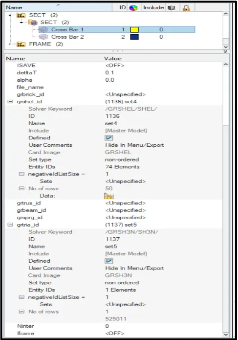
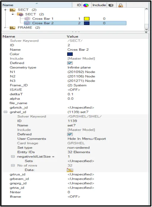
fig - Cross-Section Parameters
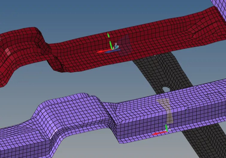
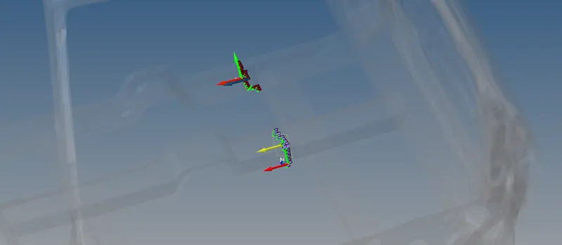
Fig - Section & Frame Location
Two rows of elements are selected across which the section force has to be calculated. The N1, N2 & N3 is taken as reference frame nodes to calculate the force across this section.
2. Intrusion at B pillar, hinge pillar, and fuel tank region.
Intrusion here means how much displacement the driver is facing near the B-Pillar or from the side door when there is some crash. For this, we introduce 3 points on the rocker arms and then calculate the displacement of this intrusion based on the forces received after impacting the pole.
3 nodes are selected to record the intrusion - 123298, 123321, and 123362.
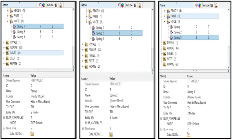
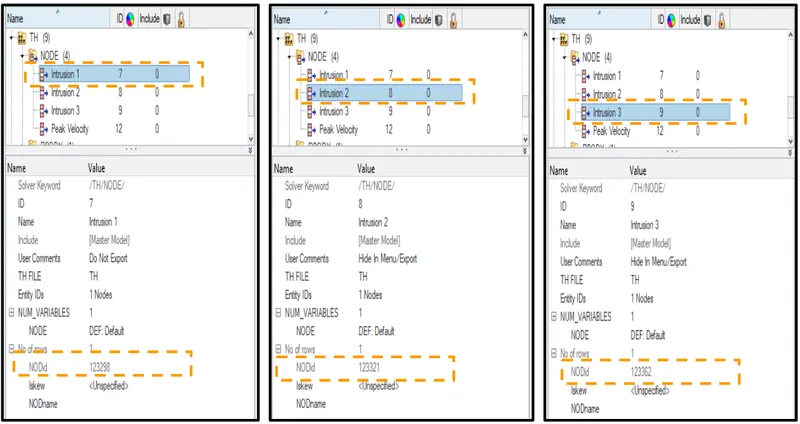
fig - TH Node Parameters
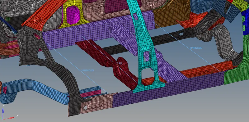
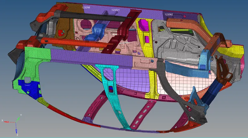
fig - Spring Assign between 2 nodes
3. Peak velocity of the inner node of the door.
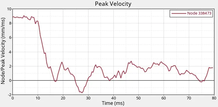
In this, we select one node in the inner door panel to observe how much velocity is generated after hitting the pole. The node 338473 is selected to record the velocity. In /TH node is added w.r.t to node 338473.
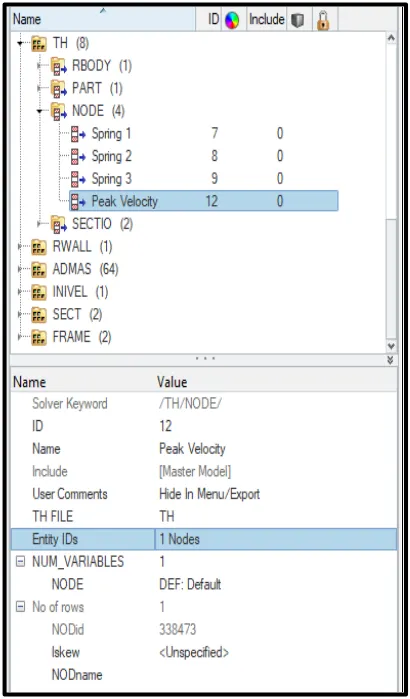
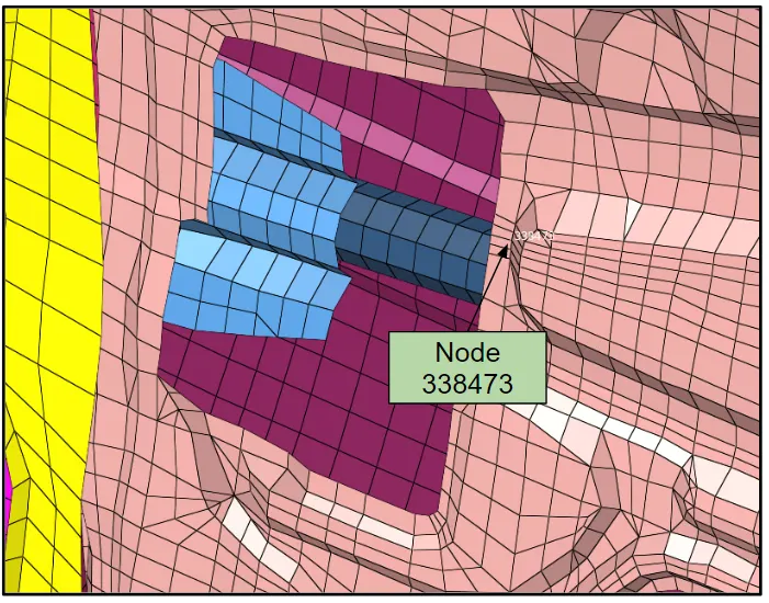
fig - Peak Velocity Inner Door Node
Model Check
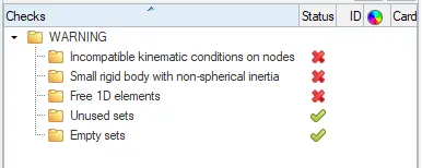
fig - Warning in Model Checker in Hypermesh
After running the model checker there was no error is in the model but some warnings related to the incompatible kinematic condition, small rigid bodies which are ignored, and simulation is set to run.
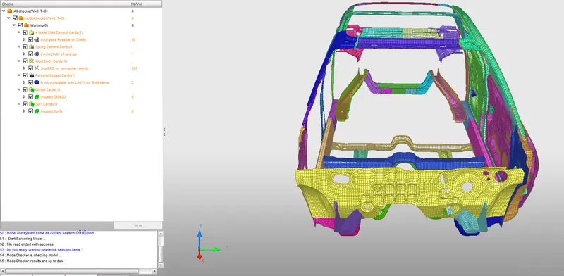
fig - Warning in Model Checker in Hypercrash
Results:
1. Sectional force in the cross member.
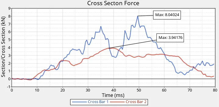
During the side-impact, the vehicle is going to impact the cylindrical rigid wall. At the time of impact, this vehicle will have some kinetic energy possessed and the rigid wall will try to oppose this kinetic energy and itself will apply the force from the opposite direction as shown above. So while impacting the rigid wall the kinetic energy of the vehicle will be reduced continuously and at the same instance, the wall will apply force to the vehicle components due to the transfer of energy. From this, we can conclude the force will be recorded in the vehicle components due to high collision and it can be either positive or negative based on how much particular component is going to deform and how much force it is absorbing from the rigid wall.
From the above graph, we can say that the vehicle is going to impact the cylindrical rigid wall with some initial velocity, and from our observation, we can say that the same force applied by the rigid wall it is been recorded in the crossbar component at the section frame. Here the crossbar is absorbing more forces than crossbar 2. This difference in the cross-section is due to the component located at a different location and depending upon the displacement of the particular cross-section component. The maximum force recorded in crossbar 1 is around 8.04 kN and that in crossbar 2 is around 3.94 kN which is displayed in the above graph. The force is so high because as explained above a large amount of force on a small proportion of the side of the vehicle is imposed.
2. Intrusion at B pillar, hinge pillar, and fuel tank region.
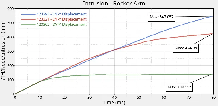
Here we can see that after the side-impact the intrusion is recorded in the form of displacement. This intrusion node 123298, 123321 & 123362 are near the driver side B-Pillar in the rocker arm component. As there are no other components in the middle section of the vehicle like the absence of Engine, Radiator, Seat, Other Assemblies, etc there is very huge deformation recorded at these intrusion nodes. This can be fixed after fixing the other parts inside the BIW Structure. The maximum displacement recorded in 3 nodes is displayed in the above graph. The displacement is so high because as explained above a large amount of force on a small proportion of the side of the vehicle is imposed.
- What can help to reduce the fuel tank intrusion?
--> To counterbalance this intrusion we can add the reinforcement structure near the fuel tank and inside the door panels. Additionally, we can add the cylindrical beam with a higher thickness of up to 4-5 mm can be provided the additional strength to avoid the fuel tank intrusion.
3. Peak velocity of the inner node of the door.
Energy Plot
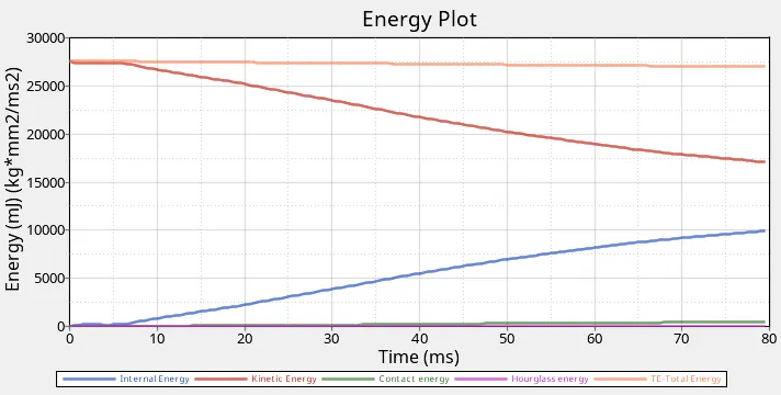
From the above graph as usual we can see that the kinetic energy and internal energy are decreasing and carrying accordingly. As the vehicle is impacting the rigid wall the kinetic energy of the vehicle is converted into internal energy. The total energy is the summation of the kinetic energy and internal energy.
Total Displacement in the Vehicle
Total displacement recorded due to side crash pole test is 797 mm which is taking place due to no other components present in the model.
Total Von Mises Stree in the Vehicle
Total von-mises stress recorded due to side crash pole test is 3.17e-01 kN/mm
Learning Outcome -
1] Setup the model for the Side Crash Analysis using HYPER-CRASH & FEA HYPER-MESH.
2] Types of force need to be calculated during the RADIOSS analysis.
3] Side Crash Analysis Fundamentals.
Conclusion -
Here we conclude that this project is completed. Learning throughout the project of CRASH-WORTHINESS of Side Pole Impact Analysis is very much worthy and can be applied to the industrial realistic problems of CRASH-WORTHINESS.
- Shaik NurullaAwesome project. Keep it up. Well Deserve