Assignment 7
Side crash analysis
The main aim of this project is to perform the side crash analysis of the neon dodge reduced model. The side crash test is setup according to the standard crash testing procedures and the crash is simulated accordingly. The side crash is performed to gauge the safety of the passengers receding in the vehicle. The main objective is to understand the effect of collision on the BIW due to crash.
BIW is basically a joined automobile structure, all the frame components are joined using various joining methods such as rivets, bolts and welds. The name BIW is given due to the fact that the entire component in painted in white. BIW plays a vital role in the crash scenario. It takes up most of the impact load and the keeps the occupants safe and sound. BIW should possess some well defined mechanical features. It should be rigid enough to protect the occupants and it should deform enough to take the impact loading.
It is so important to design the vehicle which is crash worthy. The simulation of the crash test provides us very essential inputs to the design team to make some important modifications to the structure or the material. An accurate simulation of the real time scenario gives an opportunity to the engineer to understand the crash mechanics and design a better product which is crash worthy. Certain parts of the BIW are crucial during the side crash. They take significant amount of loads of the remaining structural members. In this project we analyze the force distribution among these components and their behavior during the crash.
- Case Setup:
Altair Hyperworks is used to simulate the side crash of a neon dodge. Various important parameters such as the contact definition as well as the rigid wall definition and the section creation and the force analysis is done. A detailed description of all the above mentioned is given below.
1.1.Contact
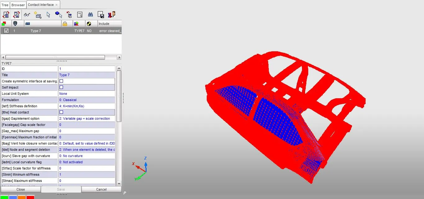
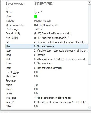
The BIW model is given pre meshed, we will start up with the definition of the contact region. A type 7 contact is used to define the contact. As per the recommended criteria a type 7 contact is established. The type 7 contact is sufficient for the contact modeling as the there wont be any significant edge to edge contact.
1.2 Units:
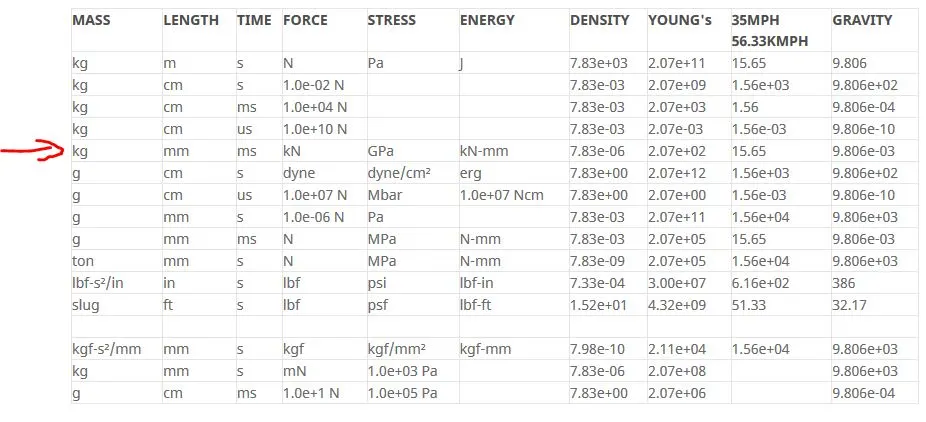
It is essential that a consistent system of units is followed throughout the analysis. We can guess the unit system of the model by observing the units of the mass. We have to open the model in hyper crash and then we have to proceed to
mass>balancing
The mass of the components as well as the point masses can be seen in the palette. According to the consistent unit system we can predict the units of the model. We can even see the format of the density. The pictures of the units of the mass and the density are shown below.
1.3 Centre of gravity:
The position of the center of the gravity is very important for an automobile as well as the crash simulation. Initially the COG is towards the center. Necessary addition of mass is done to shift the COG to the recommended position.
The mass can be added through the added mass. As we can see from the picture the mass is given as point mass and the value can be changed to add or remove mass.
Suitable mass is added so that the COG is brought back and the overall weight approaches 700 kg. After the addition of the mass at different positions the overall weight reaches 695kg and the COG position is moved to the recommended position.
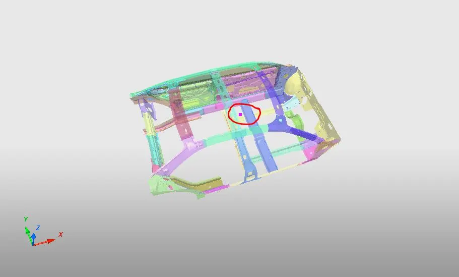
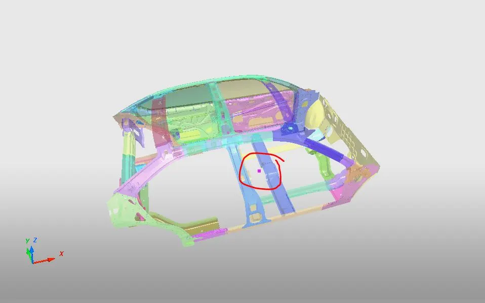
Intial COG Final COG
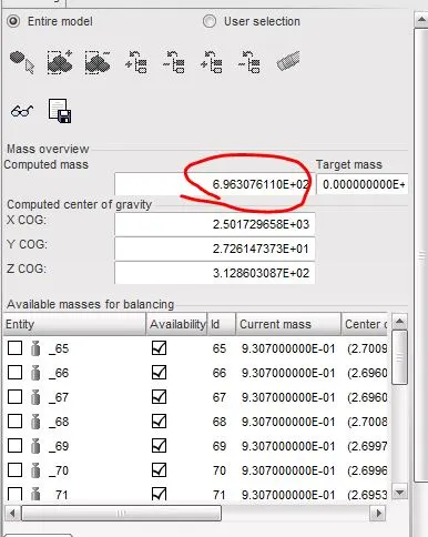
Final Mass
1.4 Free and additional rigid bodies:
As we are dealing with a subsystem there might be few parts which are free and are not properly connected. These can be either connected properly or they can be completely deleted if not necessary. The free parts can be checked using the connectivity of the parts option in the menu bar in hyper crash.
Quality>Check connectivity of tree connection.
The entire model tree is selected and the connectivity is checked using the above mentioned option. We can see three free parts in the name of door lock plate and one below the Cross rail. A connection between them is established with the help of rigids and the springs. The free parts as well as the tree showing the free parts is shown in the below image.
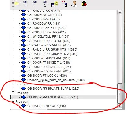
Free parts shown
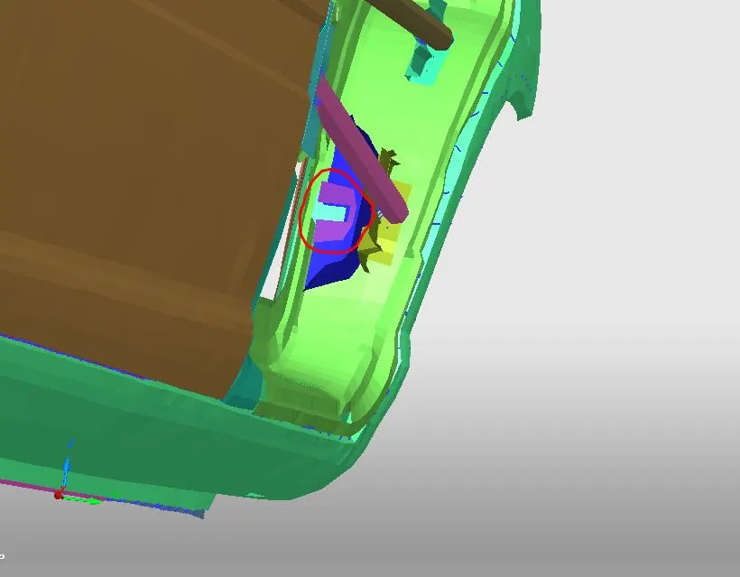
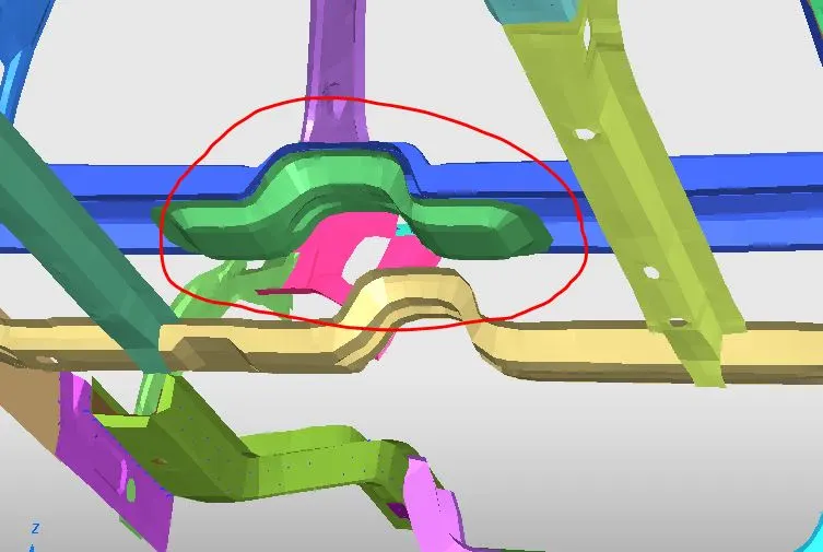
Door Lock Plate Free part under rail
1.5 Rigid wall :
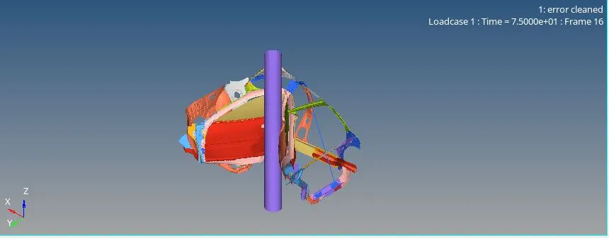
A rigid wall is created as a barrier for the crash analysis. The cylindrical rigid wall of diameter 254mm is created in hyper mesh using the node selection and the normal direction for the wall. The Dsearch distance is given 600. The wall created at the B pillar as per the standard testing protocols. The size of the wall and remaining parameters are shown in the below picture.
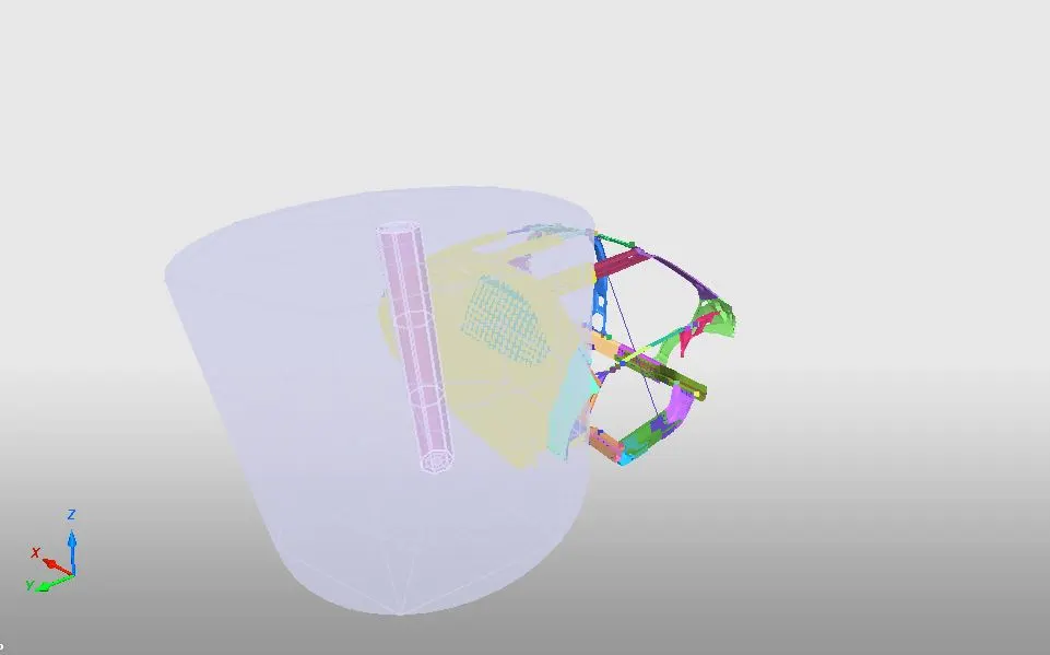
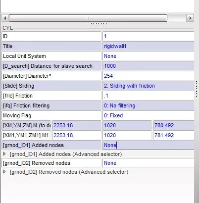
Rigid wall Rigidwall properties
1.6 Boundary conditions :
The boundary conditions for the problem is our automobile is moving at a velocity of 35mph. Converting it into the present unit system it is 15.65 mm/ms. The velocity is given to the total group of nodes as they will be moving at a velocity of towards the wall. The intial velocity condition is shown in the picture below.
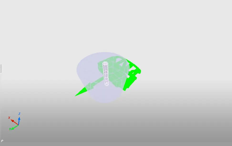
Initail velocity
1.7 Section creation :
As said in the introduction there are few vital parts in the assembly of the BIW which take most of the impact loads. They include the cross members. When the vehicle comes into contact with the pillar the cross members will take most of the load and they prove to be the crucial components of the BIW. They are closely observed and the forces in them are monitored with the help of sections. Sections are created at the members and their respective normal and tangential forces are observed through output requests.
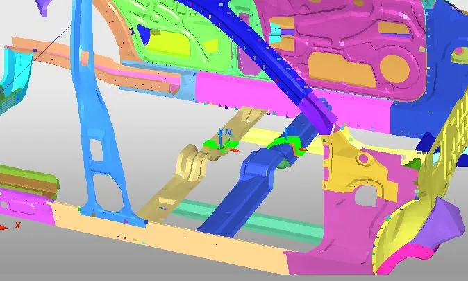
Sections created
1.8 Peak velocity and fuel tank and other intrusions
Peak velocity at the door of the driver is crucial for any crash analysis. So the velocity output request is generated at the prescribed node near the driver. The position of the node at which the peak velocity is generated as well as the fuel tank intrusions and other cross member intrusions is shown in the picture below.
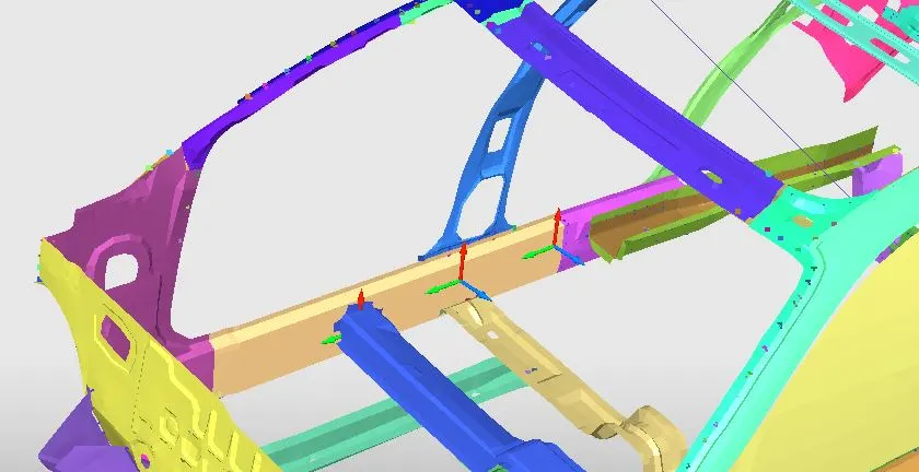
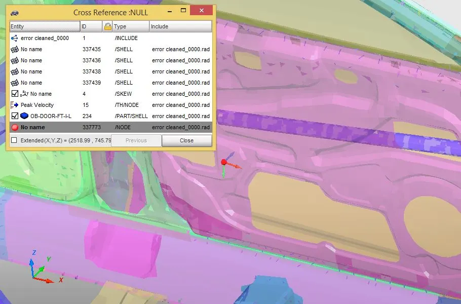
Systems to find out displcements Node for peak velocity information
1.9 Nodal time step:
The time step need to be changed as per the required value. The change in the time step can be done using the DT/NODA card. The time step of 50micro sec is adjusted in the panel and it is converted to the required units ms.
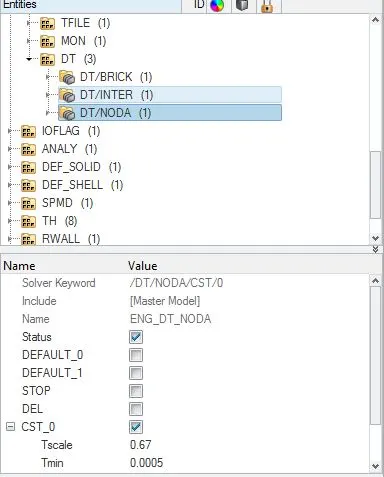
Time step control
1.11 Output requests :
A total of 11 output requests are created to check the results. The output requests created will generate the data which is helpful later in plotting and understanding the physics. The output requests include acceleration, Normal and tangential forces at all the sections and at the rigid wall and the elongations of the intrusions were created.
The picture below shows the position of the output requests in the tree and a sample request.
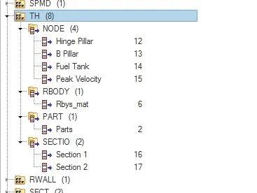
- Model checking and debugging:
- To ensure that there are no errors we use model checker in the in hyper crash.
- We need to make certain that there are no penetrations and intersections in the contact interfacing and the components. This is done using penetration check in the tools option in Hypermesh.
- But as the model was run in the solver there were few errors in the initial runs as to the placement of the rigid wall.
- As a result due to incompatible kinematic conditions 99 percent energy error is shown in the solver.
- This is issue is resolved through proper definition of the rigid wall so no free edges or elements fly away from the problem.
- Once the errors are debugged and the model is ready to solve.
- Results
The results include several output requests that were requested and the peak velocity and the displacements at the required locations.
Sectional forces :
- The sectional forces at the two cross members are shown in here below .
- For cross member 1 a maximum normal load of 6KN is obtained at the cross-section at 20ms.
- Similarly at cross member 2 a maximum normal load of 4KN is observed around 18 ms.
- As a matter of fact the cross member is directly opposite to the pillar as a result maximum normal force is obtained over there.
- The BIW starts impacting the wall at 15ms and we can see a spike at that particular instant and when the cross member starts buckling the force spikes up again and as a result the we can see a spike somewhere btw 34ms and 40ms.
- The graphs of the resultant normal as well as tangential forces for both the members is shown in the figure below.
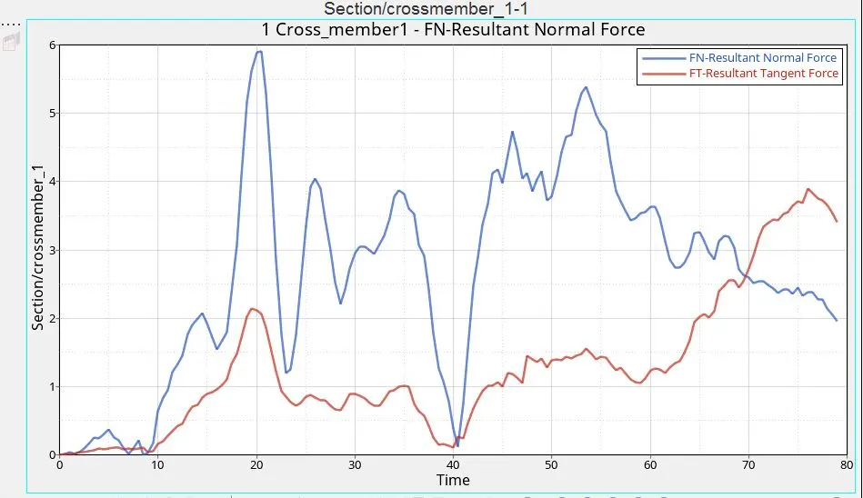
Section 1 Normal Section forces
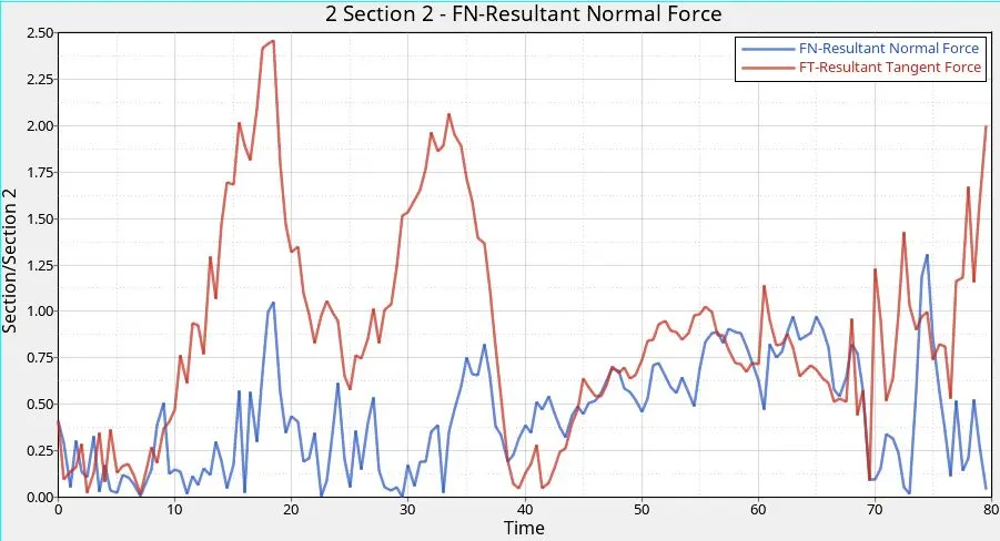
Section 2 Normal Forces
Peak velocity:
- The peak velocity graph shows the velocity variation of a particular node as requested in the assignment.
- The vehicle is moving towards y direction with an initial velocity and after the point of impact we can see the velocity of the point goes negative and peaks until -2.8mm/ms.
- The graph of the peak velocity in x, y and z directions are shown in the pictures below and similarly the displacements.
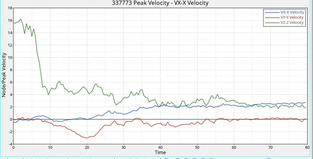
Peak Velocity Plot
Displacements at fuel tank
- Intrusions at particular locations are found out the values are shown in the graphs .
- The intrusion at the B pillar as well as at the fuel tank is shown in the pictures below.
- A maximum intrusion of around 150mm is observed at the in the y direction for the fuel tank and similarly an intrusion of around 600mm is observed at the b pillar.
- The y displacement for fuel tank peaks at the end where as for the b pillar it reaches max value in the middle.
- This is evident from the fact that the B pillar impacts first and the cross member at the b pillar crushes first and then it stops but still the material around it still will be in deformation.
- That is the reason why we have different points of maximum deflection at different locations.
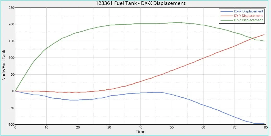
Displacement at the fuel tank
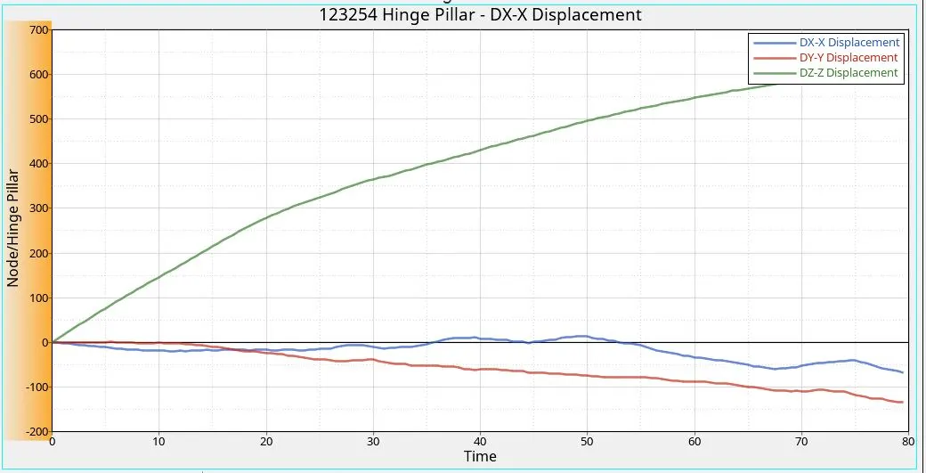
B Pillar displacments
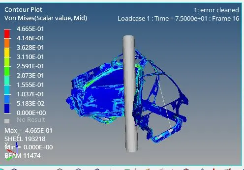
These were the results and the plots those our obtained after doing the side crash analysis of a neon dodge model.
The energies such as kinetic and the internal energies are also plotted and the kinetic energy starts at a maximum value and reduces over the duration of the simulation. As a contrast the internal energy increases as the simulation progresses and peaks at the end due to the increase in the deformation.
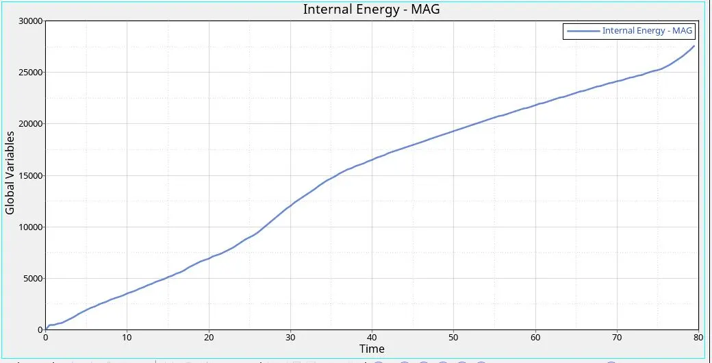
Internal Energy
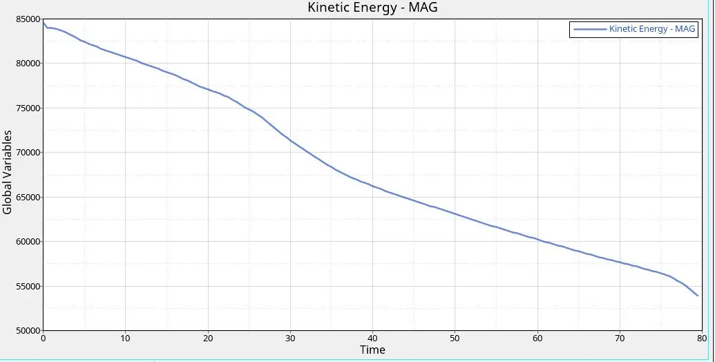
Kinetic energy