Assignment 7
Objectives :
- To experience Side crash simulation check
- To learn inputting the necessary input condition for crash such as Rwall, Invel, Addmass.
- To control simulation time using the DT control card.
- To opt for output such as Sectional forces, Specific element deformation, and various energies.
- To check Nodal deformation and peak velocity change by creating Time History TH Node with the Skew system.
- To run the final quality checkup.
Case Setup:
1. Model Import & Initial Check:
Opened Neon Side Reduced 0000.rad file to see the default unit system.
The unit system found to be: Kg-mm-ms.
Checked Consistent Unit system for Altair on Google and noted down the updated values for various quantities like:
For density = 7.8e -6 & E = 210Gpa, values found to be speed 35 MPH= 15.65 mps & Gravity = 9.81e-3.
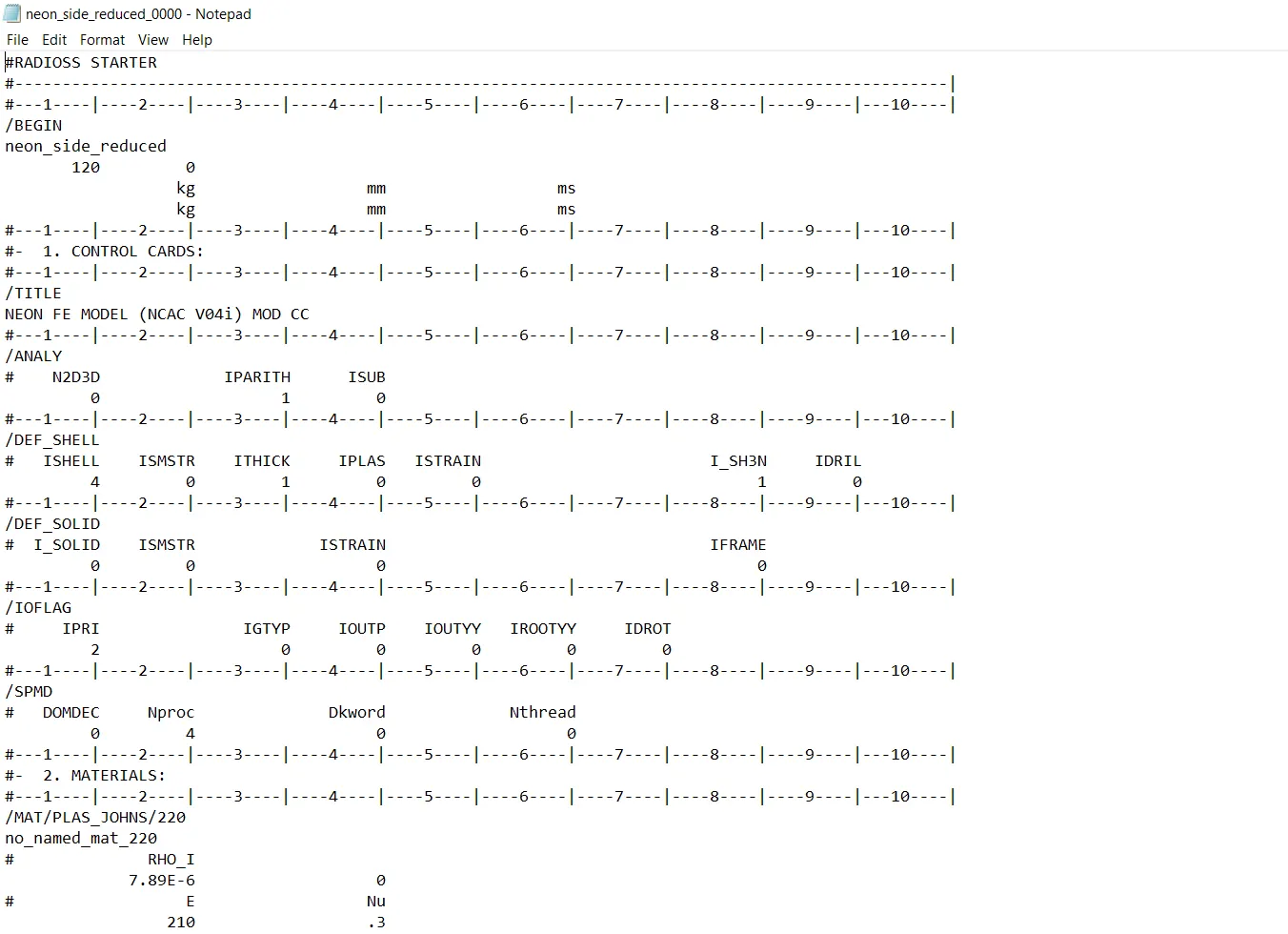
Imported Neon Neon Side Reduced 0000.rad file to Hypercrash.
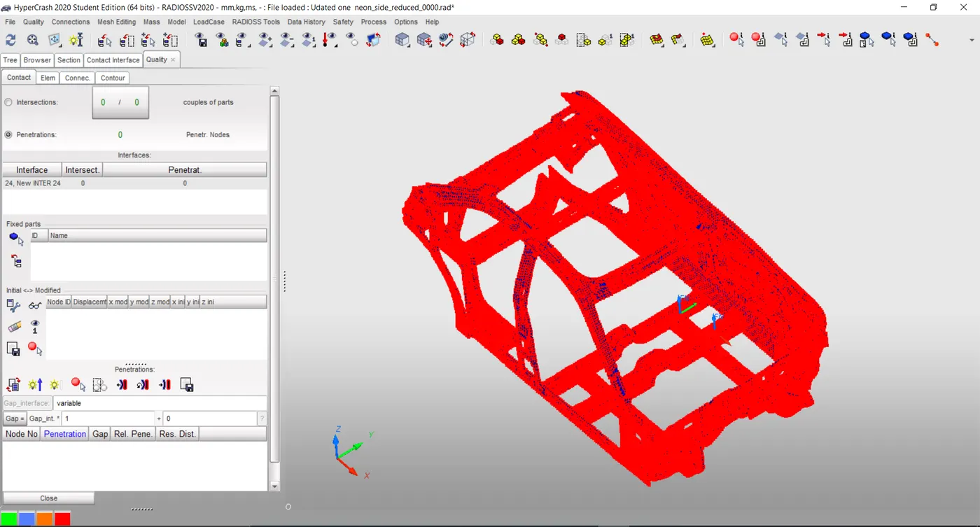
Performed penetration check-in the contact interface module & found zero penetration.
2 Input Conditions:
Basic Input Conditions:
Rigid wall:
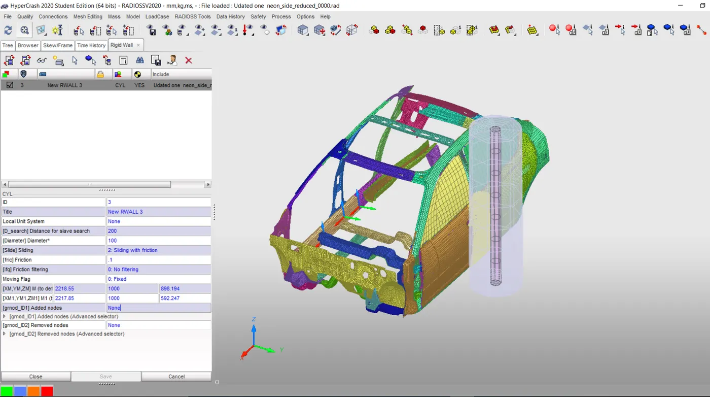
Created the Cylindrical Rigid wall by picking the Door lock node with 100mm Dia and maintaining both head and tail node values equal initially.
The tail value then moved by 400mm in Y direction to remove direct contact.
Dsearch value inputted as 200 and Sliding friction as 0.1.
Initial Velocity:
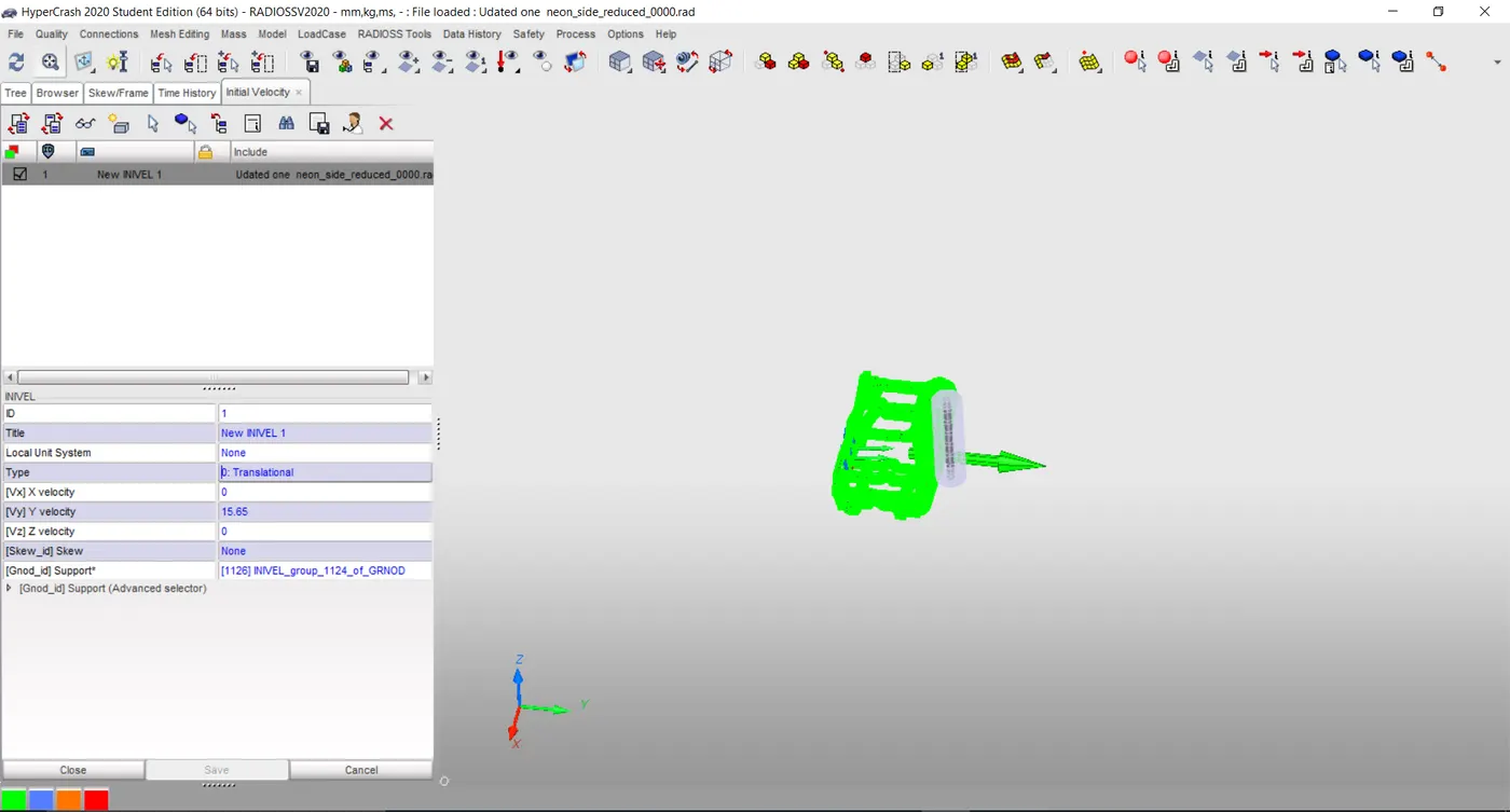
Initial velocity is given 15.65 for 35MPH speed as discussed earlier in the positive Y direction.
Contact Interfaces:
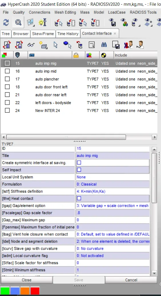
Type 7 Contacts: Inputed all the recomended values such as Igap=2, Gapmin=0.5, Inacti=6, Istf=4, Stmin=1000, Idel=2, Iform=2 etc.
Checked all shell elements properties.
Desired Input Conditions:
Added mass:
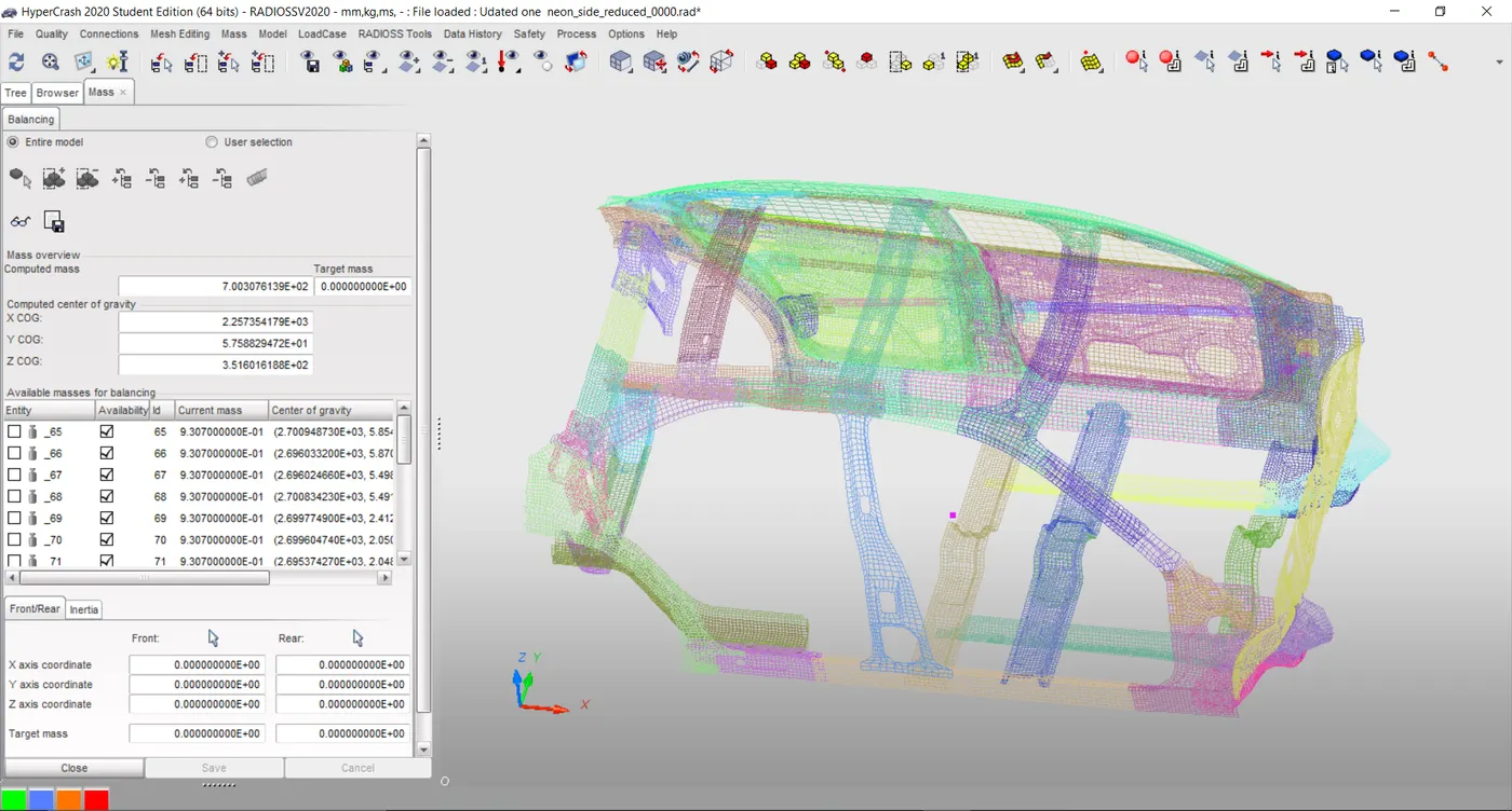
The default mass of the vehicle found to be = 166 Kg.
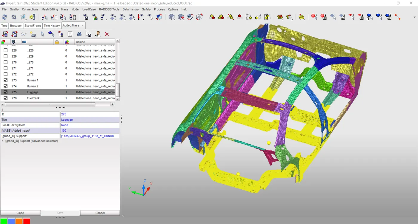
In order to reach 700Kg Extra 534 Kg mass distribute in four sections such as in back bumper 100Kgs as Luggage, For Fuel tank 134Kgs, For Front two seats 150Kgs each as human weight
in order to maintain the CG point in an appropriate location.
Options Type 1 selected for mass distribution over the selected node groups.
Gravity Load:
As of this model didn’t consider gravity.
Time step Control:
By default in Control card-Engine- Anim DT & DT ELTYP IFLAG were present.
In order to further reduce the time I could have used DT Noda & DT Inter method by giving 5 us as critical time with a scale factor as 0.9. But Ignored because of default conditions.
3. Output Request:
Section Forces:
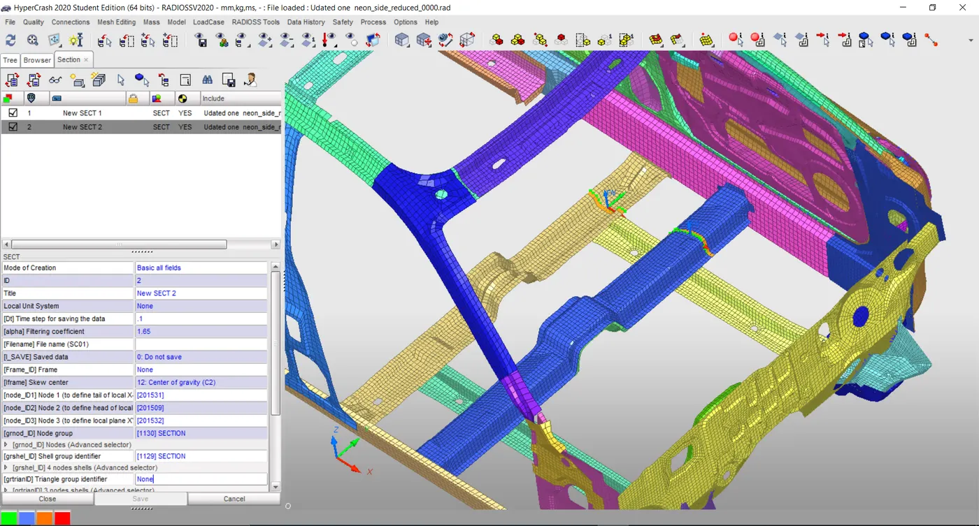
Crated Two sections at Both snake members present at the foot section connecting B pillar using 3 node option.
As it got saved in Data history automatically no need to create it separately.
Intrusion Check :
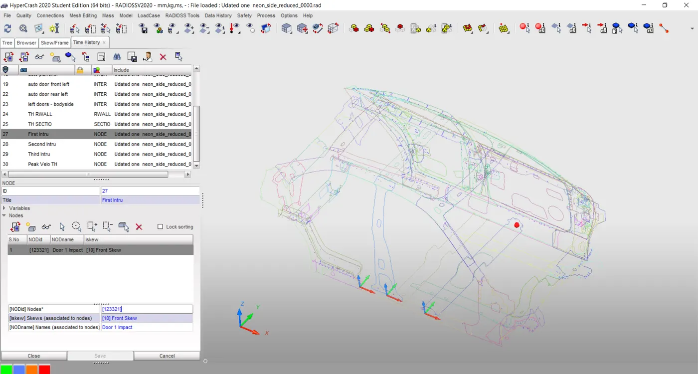
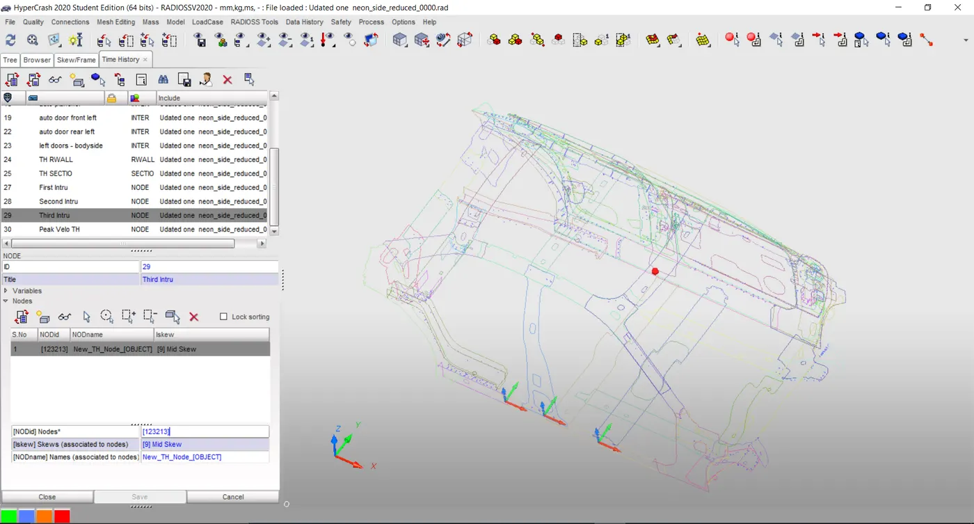
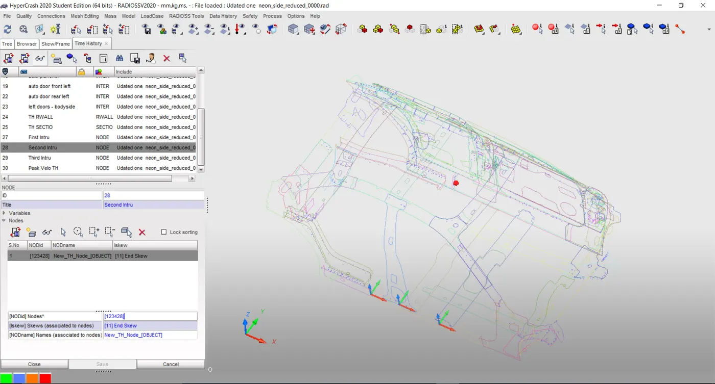
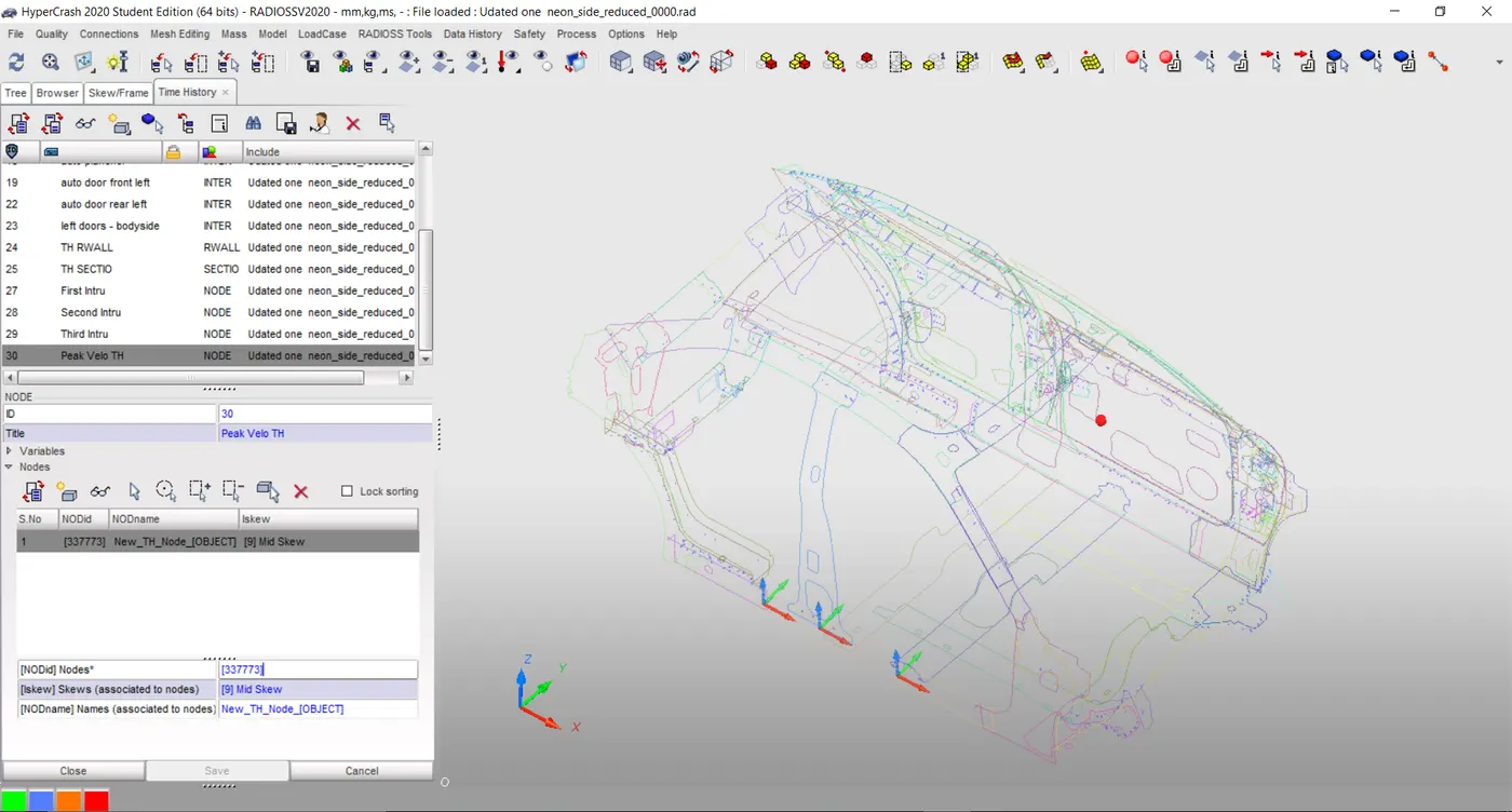
Intrusions have been checked at B pillar, Hinge pillar, and Fuel tank region by creating TH node in the Data history plot at the respective point.
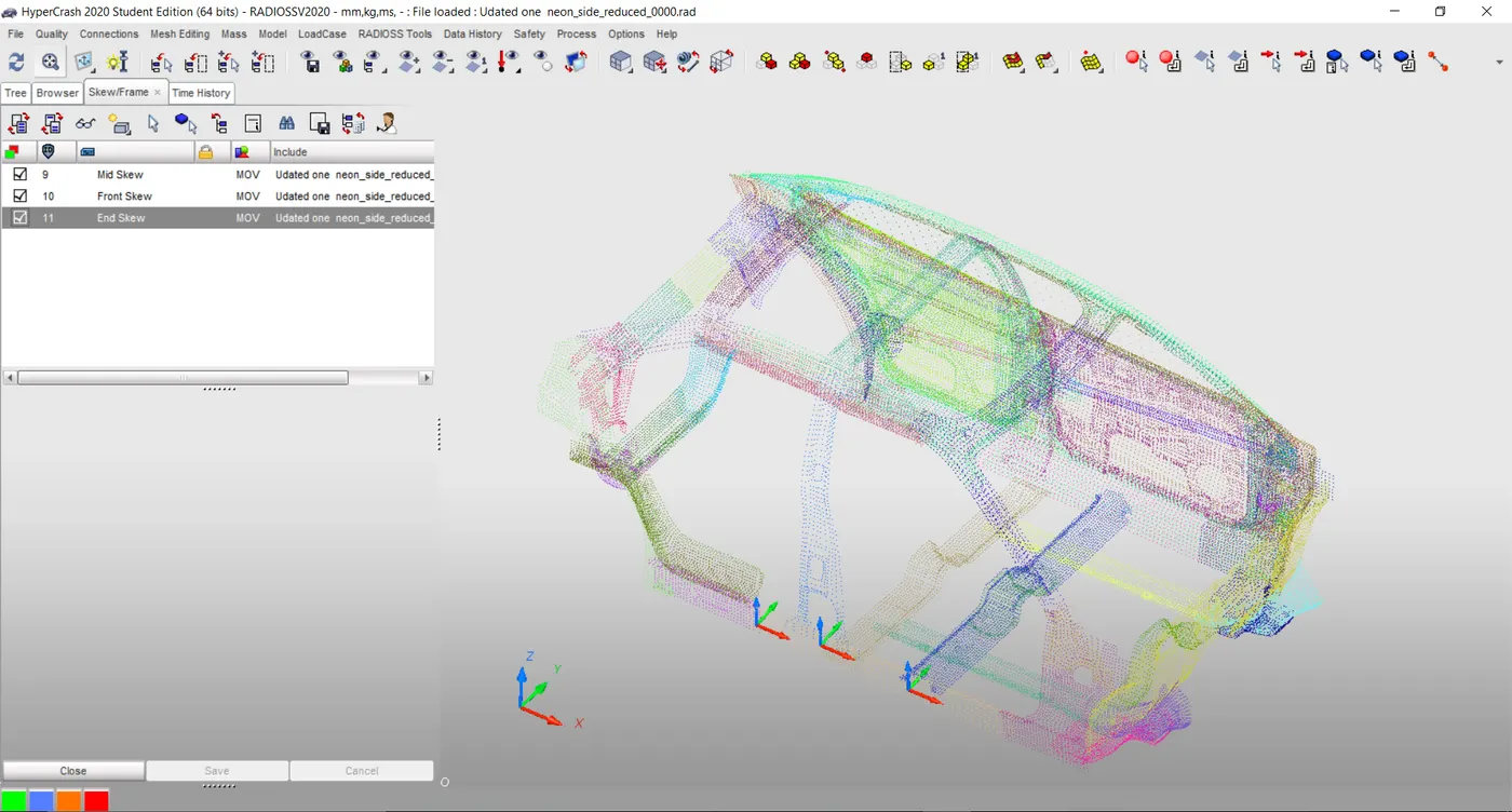
In order to have an uninterruptible nodal point Skew/Move system created for each.
Peak Velocity:
Peak velocity checking being performed for the Inner door panel center node.
As previous activity here also the B pillar skew being used for the middle TH node point.
Model Checker:
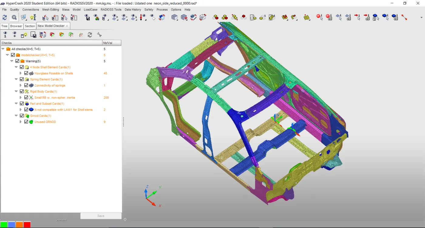
Run model quality checker and warnings found to be normal.
4. Results & Discussion:
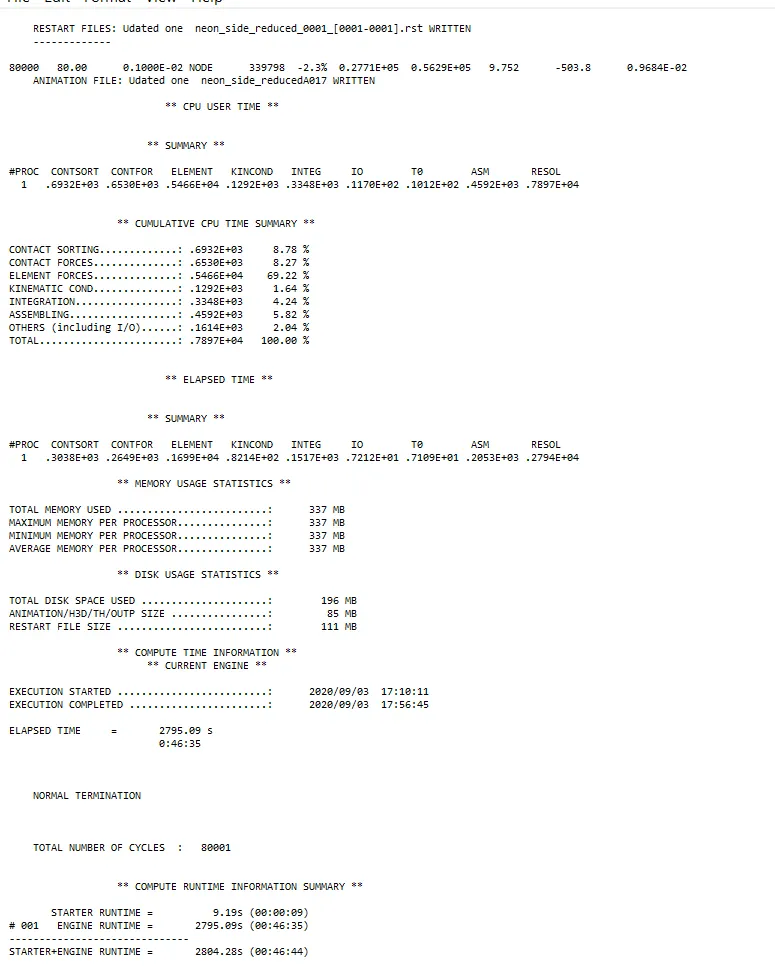
After completion of the simulation, run checked the engine output file.
Simulation time was found to be of 2804.2 sec with a mass error of 0.96e-2 which was less than 2%.
Forces:
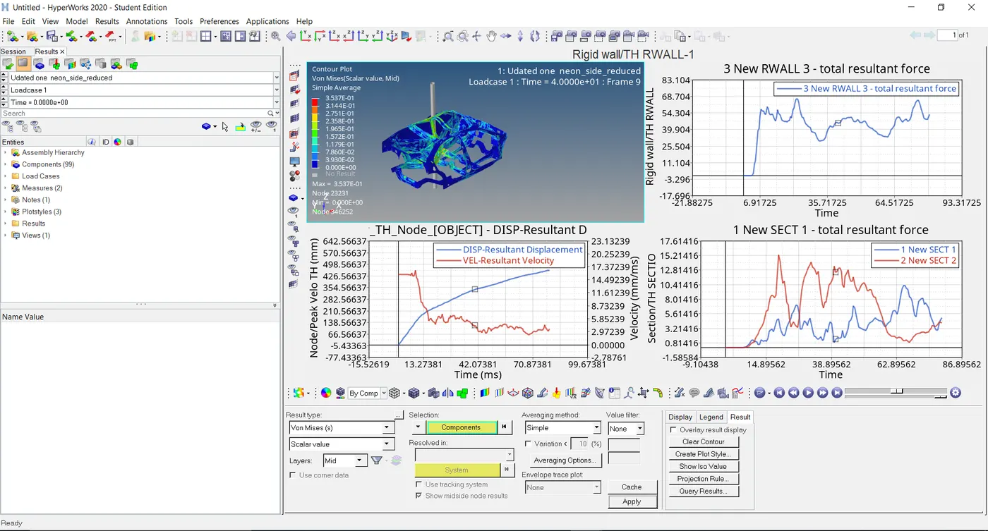
Max section force was found to be 15.21 KN which occurred on the B pillar section as It was the nearest one to the Pole.
On the other panel, Max sectional force was found to be 10.41 KN.
Max rigid wall forces found to be 65KN.
Peak Velocity:
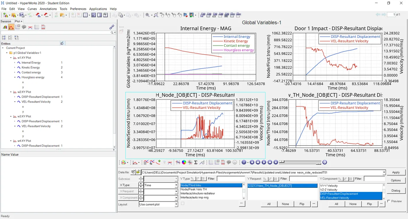
The peak velocity at the door lock region node was found to be 426.56 mm/ms.
Intrusions:
Hinge pillar intrusion: 716 mm
B pillar intrusion: 284 mm
Fuel tank panel intrusion: 1.2e+8mm
Energies:
KE & IE started their initial curve deformation point from 10ms.
Max KE was found to be 8.75e4 KN-mm.
Very less Hourglass energy generation was found.
Observation & Recommendation:
As for the other two nodes, the intrusion was found to be in the range of e+2 while for the Fuel tank panel it was hiked to e+8 order.
By common observation, it is noticeable that the absence of any supporting member for the same.
Hence either anyhow there should be an addition of extra member or the Fuel tank must act as a Cross member in order to enhance the rigidity of the structure.