Project - 2 [Side Crash Test]
OBJECTIVE
- The first objective of side crash analysis of Neon BIW to know the force that recieved at different components of BIW on cross members and to know the Intrusions at B pillar, Hinge pillar and fuel tank region
- The second objective of side crash analysis of Neon BIW to know Peak velocity of inner node of the door
CASE SETUP AND EXECUTION
1. Import the model by using the option import Solver deck
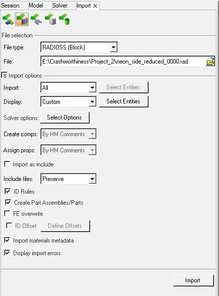
Fig:1
MODEL
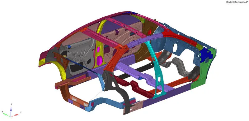
Fig:2
2. Check the unit system by following the Kg mm ms unit system for the whole process
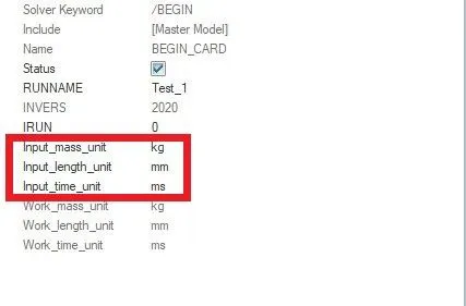
Fig:3
3. To create appropriate interface for the model with friction 0.2 by folllowing the recommended parameters
In this model some default interfaces are provided, this interface need to be deleted and input Type-7 Interface for the whole model, this can be done in Hypercrash
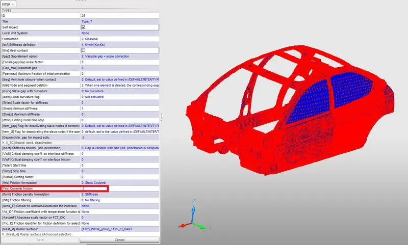
Fig:4
In Type-7 interface it is defined to be self impact which means the master and slave nodes are itself on the same body.
In the above list the recommended parameters for Type 7 interface are :
| Parameter | Description |
| Igap =2 | Set variable gap to take into account the true distance between parts |
| Gapmin `>=` 0.5mm | Specify minimum thickness of the model to avoid numerical issue. Typically half of the thinnest part |
| Inacti = 6 | Remove initial penetration possible where possible |
| Istf = 4 | Set stiffness of Interface based on the softer of master and slave |
| St min= 1Kn/mm | Specify a minimum stiffness in the contact to avoid too soft contact |
| Idel = 2 | Remove slave nodes from contact because of element deletion |
| Iform = 2 | Sliding force are computed using stiffness parameters of the interface. Usually results in bigger time step |
4. To check there is no penetrations and intersection on the model
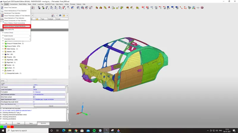
Fig:5
[Fig-5 : To check the penetration]
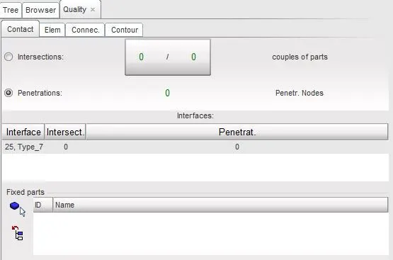
[Fig-6 : Penetration checked]
5. To create rigid wall :
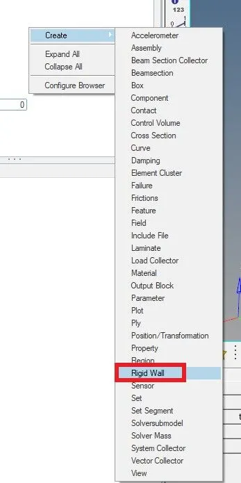
[Fig-7 : Rigid wall is created]
After setting up the Rigid wall the coordinates of the infinite plane need to be defined and normal need to setup and with friction 0.1
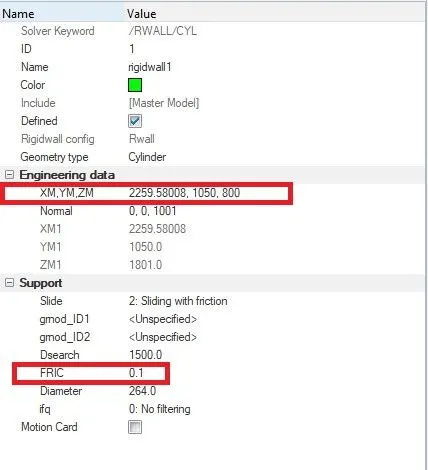
Fig:8
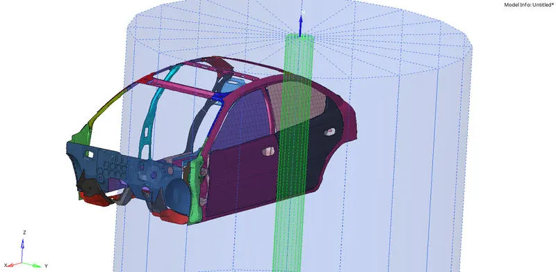
Fig:9
6. Add masses to reach target weight 700kg to set CG about the required range.
In this the center of Gravity need to be setup on the center of the whole model, so the mass need to be added and balance the CG at the center.
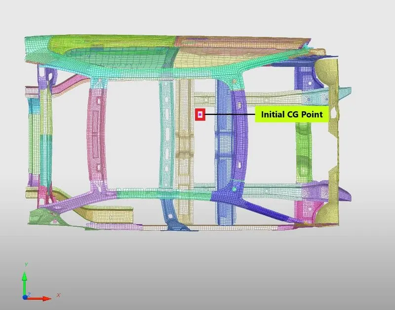
Fig:10
This is done in Hypercrash, in Hypercrash open the 2 tabs that is mass balancing and add mass. In mass balancing the total mass will be shown and Center of Gravity point is also visible. Initially the model has a weight of 188.42, so this mass need to be changed to 700kg. This is done in the tab Add mass and When adding the mass the CG should located at center of whole model.
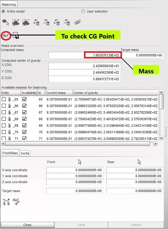
Fig:11
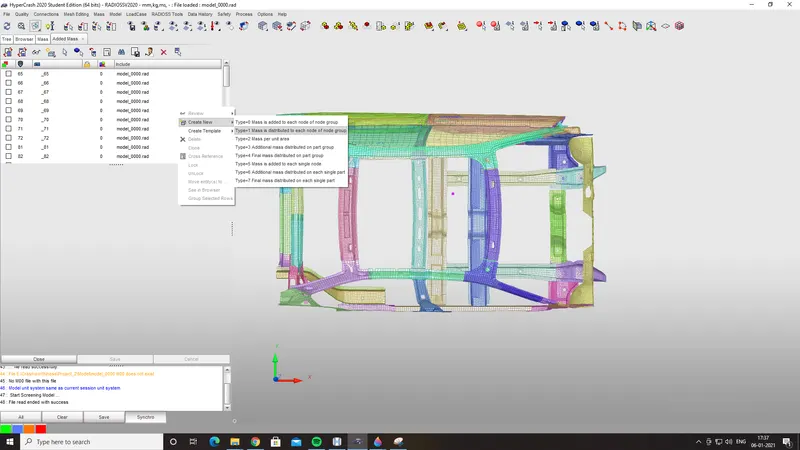
Fig:12
Adding mass means mass are created on some of the areas according to CG point, the mass will assigned based on that.
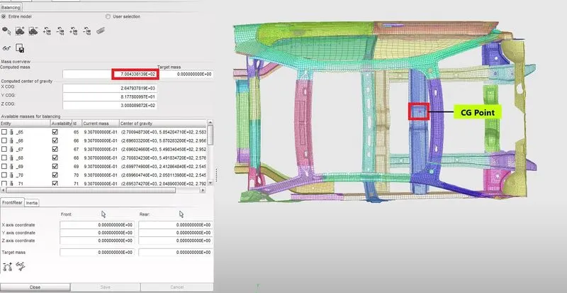
Fig:13
7. Initial velocity 35 mph
It is requied to create initial velocity in order to perform the crash. Generally the initial velocity value is given to be 35mph which is standard value according to the crash standards. In this the unit system that are followed in kg-mm-ms, so the value need to be changed with respect to the following unit system.
On conversion value becomes 15.64 mm/ms, so this value is applied in VY direction which is perpendicular to rigid wall.
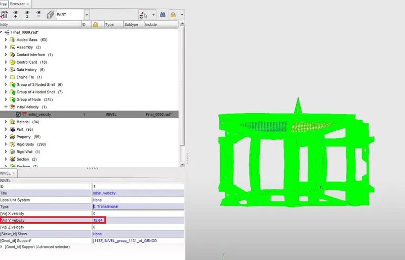
Fig:14
8. Time step and Run time
In the solver browser go to the Engine keyword , select Eng_DT_NODA and change Tmin to 0.0003 as time step. Whereas to setup the run time, under the Engine keyword select Eng_Run and change the T_stop value to 80.0.
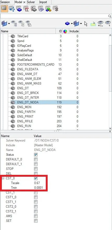
Fig:15
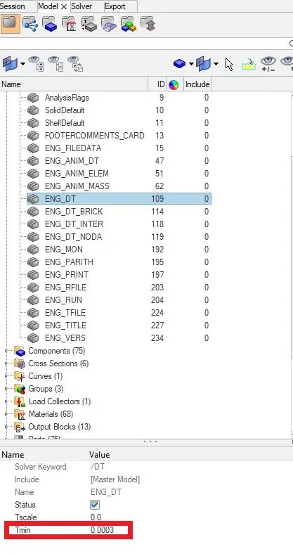
Fig:16
9. Sectional force in the cross member
The purpose of creating the section to understand how the force waves travels around a section. The section at different components a broad idea of peak force generated at a particular instant of time. This tool is very handy and helpful in understanding in depth about the simulation results.
To create section at Cross Member:
* Open the section option using the solver -> create -> SECT -> SECT option
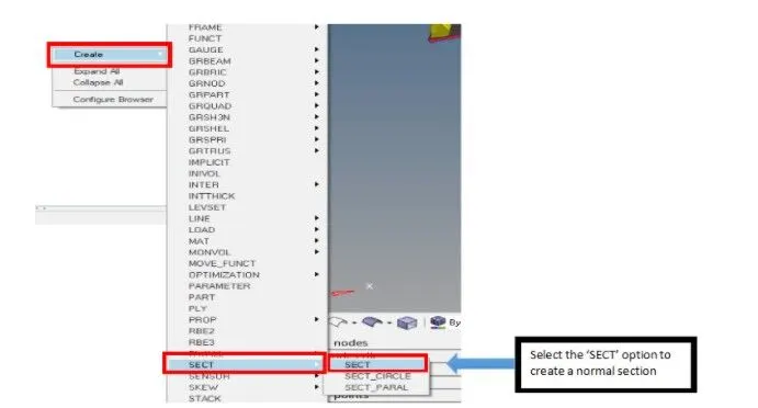
Fig:17
* Create a moving frame for the section. To create a moving frame solver -> create -> Frame -> MOV
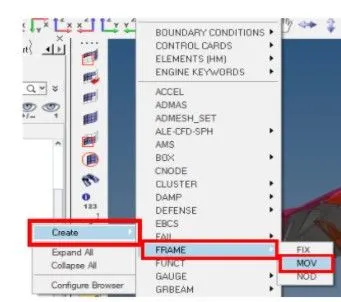
Fig:18
* Now go back to already created corss section. Select the Orgin node, Z axis direction and ZY plane.
* In the sect option , first select the frame that is already created and assign it to the section.
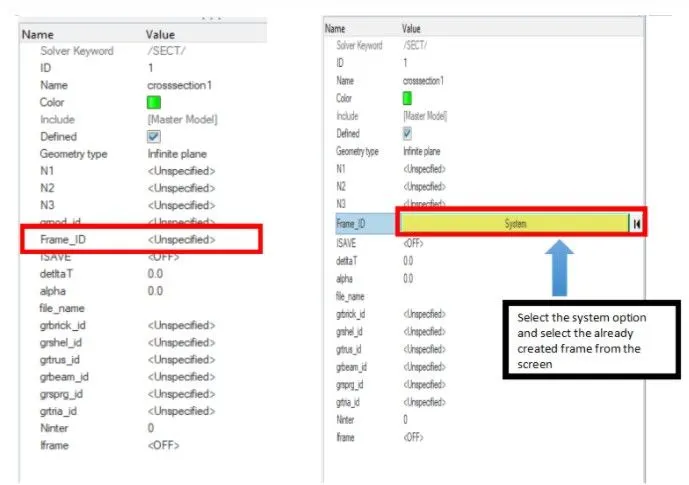
FIg:19
* Select the required shell elements in the Cross member area using the grshell_id option. Right click on it -> Create -> in the new dialogue box select the required elements by clicking on the entity id as elements
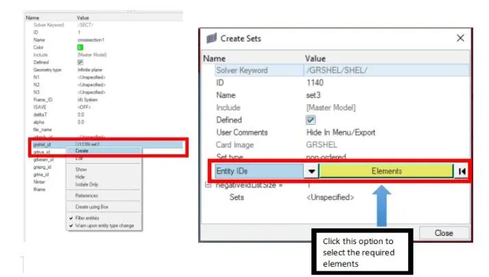
FIg:20
* Input the values for N1, N2, N3 from the seleced shell elements and input the value of Delta-T and alpha. Here the Delta-T value is 0.1 and alpha value is 1.67
Here the Delta-t is the time to start saving the section force data
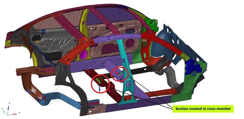
Fig:21
10. To create Intrusions in Hinge piller, B piller and fuel tank
It is created to know how much area is displaced from the respective positions.
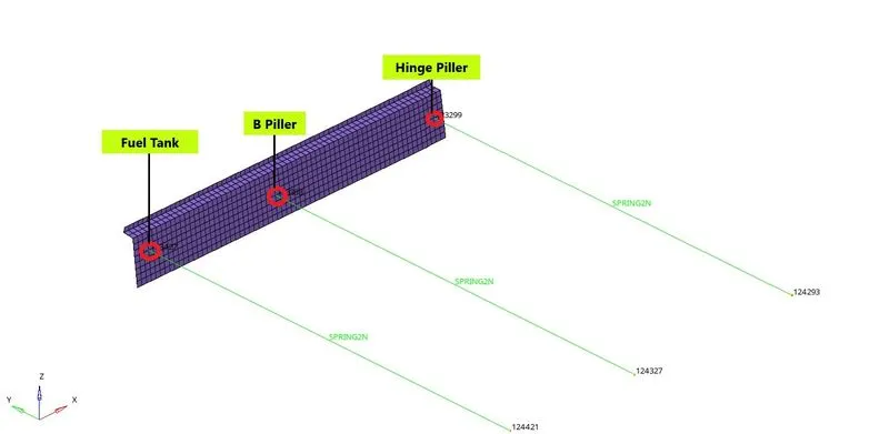
Fig:22
In these each node of Hinge piller , B piller and Fuel tank need to select and same opposite node of these nodes need to be selected. After that create spring connection between these nodes.
11. Peak velocity of inner node of the door
Peak Velocity is defined at a node in the door, so by this node TH is created in the Solver. By creating TH for this node, peak velocity graph can be plotted
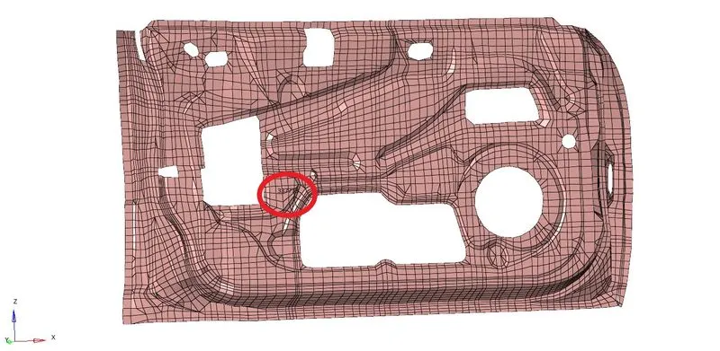
Fig:23
RESULTS AND DISCUSSIONS
SIMULATION
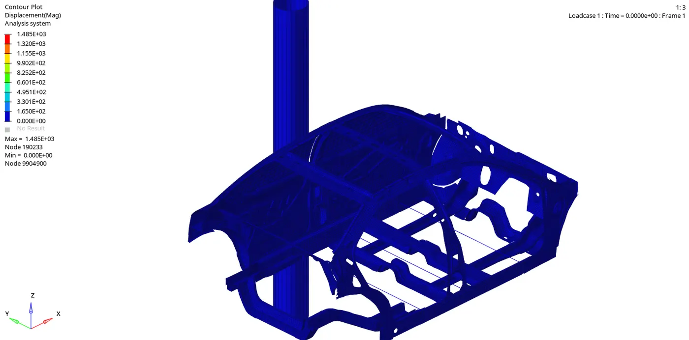
Graph plot for Internal Energy and Kinetic Energy
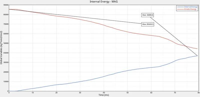
Fig:24
In this when the car collide with the rigid wall, a reaction force will generate from the wall which is the kinetic energy. This energy has huge amount of impact. If this force is taken by the passenger there is a chance of injury to passenger, inorder to overcome the injury the impact force is absorbed by the component itself. So if the component absorbed the energy the internal energy get increases. In the graph plot initially the Kinetic energy is higher and Internal energy is zero, after some time the Kinetic energy is converted to Internal energy.
Graph plot Section Forces at Cross Members
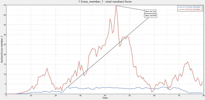
Fig:25
In here the front cross member have a peak value of about 44.722KN at 45ms, whereas in Rear cross member the peak value reaches 3.67KN at 25ms. In here the rear cross member is provided with an extra support whereas in case of front cross member does not have any support. Due to this reason the front cross members tend to have maximum force in comparing Rear cross member
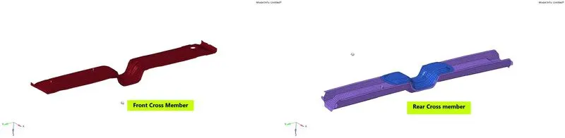
Fig:26
Intrusions in Hinge piller, B piller and Fuel tank
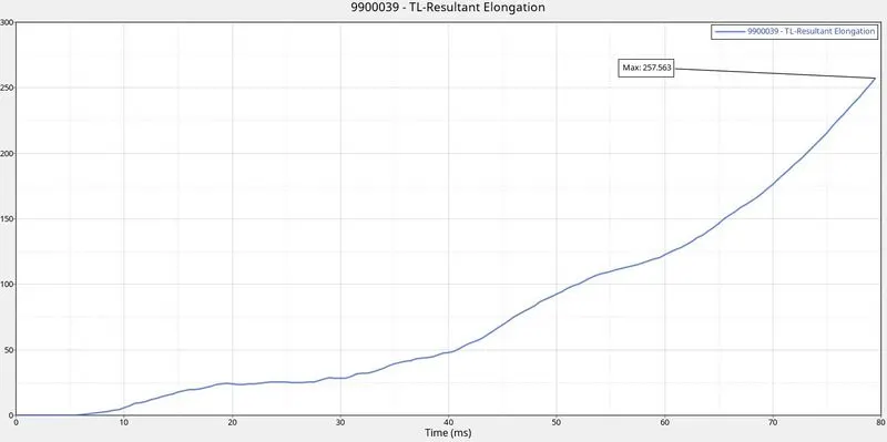
Fig:27 - Hinge Piller
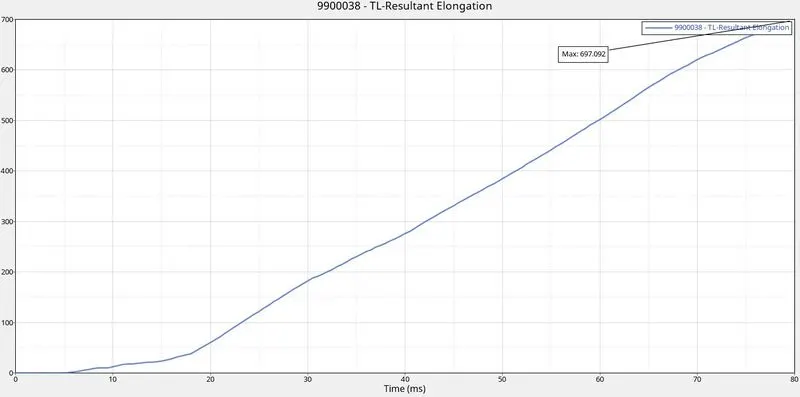
Fig:28 - B Piller
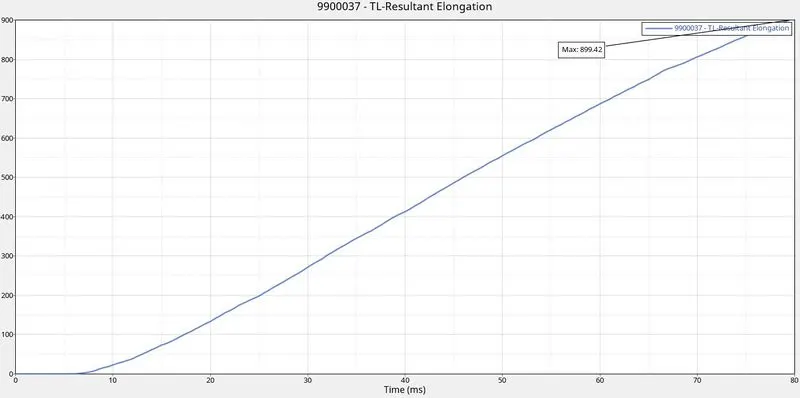
Fig:29 - Fuel Tank
Here the node number of Hinge piller is 123299, B piller is 123333 and Fuel tank is 123427
The compression in Hinge piller is 257.63 mm
The compression in B piller is 697.002 mm
The compression in Fuel Tank is 899.42 mm
In order to reduce the Intrusion in Fuel tank , a cross member need to be added on the Fuel tank region in order to absorb the energy during Impact.
Peak Velocity of Inner node of the Door
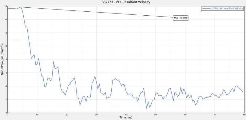
Fig:30
Here the Peak Velocity is about 15.834 mm/ms, after these peak value the velocity decreases with respect to time. This increase is due to sudden impact with the rigid wall. As initially the input imposed velocity is 15.64 mm/ms , in the graph the value reaches to that range and after that the vehicle get contact with the rigid wall. After the contact the door is getting deformed due to the impact so the velocity reaches to maximum.
CONCLUSIONS
In this Side test the main objective is to know the behaviour of a car when hits with a wall, ie to know the forces that recieved in each components of car. So by doing this the user can understand the injury affected by occupant during real crashing of car. The results will be almost similar to real scenario. In this the simulation the initial impact will be taken by the cross members then only the impact will distribute to other component areas.