Side car crash simulation
OBJECTIVE - To set up the Rigid Pole-side crash simulation of a Neon car model, in the RADIOSS solver deck as per given instructions and analyze the results.
ABSTRACT -
- Check unit system and either follow [Mg mm s] or [Kg mm ms].
- Create appropriate interface ,friction 0.2 and recommended parameters.
- Make sure of no penetration and intersections.
- Create rigid wall with friction 0.1 as per referance model.
- Compare the model weight with the referance model and use added masses to reach target weight 700kg while getting CG about the required range.
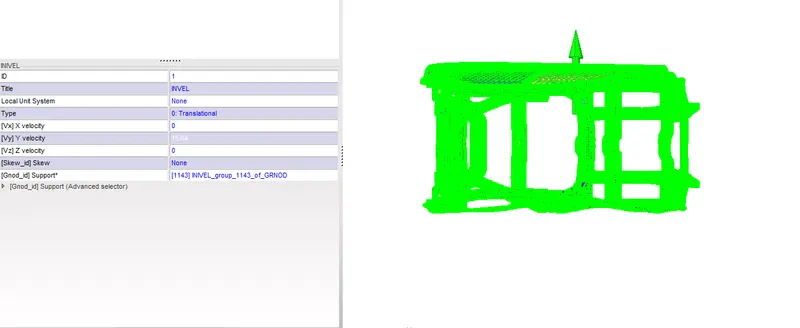
- Initial velocity as shown in picture.
- Use model checker to ensure good quality.
- Timestep :0.5 to 0.1 microseconds.
- Run 80ms.
PROCEDURE -
1. Unit system - We have to maintain the same unit system throughout the model because it leads to the wrong result after the simulation. we have to check the starter file before importing the model to hypermesh, so we came to know which unit system is applied on the model and we can change recommended units in the starter file. when I checked the starter file the units were kg mm ms.

2. Set Contact interface - Interfaces are defined to model how parts interact when they come into contact with each other or themselves. For shell elements that have a thickness assigned, a gap/space is assumed between the master and the slave nodes. Spring elements with linear/non-linear stiffness are created between the slave nodes and their projections on the master elements. This is called the interface penalty method. The linearity of these assumed springs depends on the type of interface chosen. The type of interface depends on the nature of contact between the said parts.
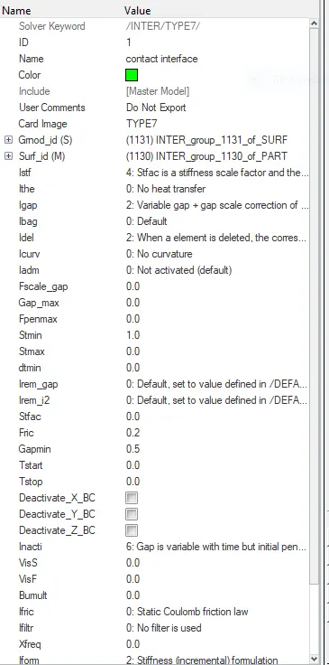
I have decided to create a TYPE 7 contact with the friction value 0.2 and recommended parameters. because type 7 is a node to surface contact. In hypermesh go to BCs -> create -> interface to create a contact interface. select the entire model for master and slave nodes to be a self contact.
Important Recommended parameter for contact interface are as follow -
- Igap - 2 (Determines how the size of the gap is calculated).
- Gapmin - 0.5 (Minimum gap for activation of the interface).
- Inacti - 6 (Action to take if initial penetrations exist).
- Istf - 4 (Affects how the stiffness of the interface is calculated).
- Iform - 2 (Friction formulation).
- Stmin - 2 (Minimum stiffness to be used in the interface).
- Idel - 2 (what to do with the slave nodes and the master segments if the elements that they are attached to fails).
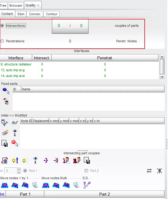
3. Penetration and intersection check - After defining the contact interface between nodes and elements, we have to check for initial penetrations and remove them before simulation. For penetration, check go to TOOLS > PENETRATION CHECK. select the group in which we want to check the initial penetration. I have selected 2 interfaces to check and there is no initial penetration present on the model.
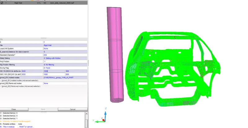
4. Rigid wall creation - A rigid wall does not physically exist but it is a kinematic condition imposed on the slave nodes. Rigid walls allow for an easy way to define an interface between a rigid surface and nodes of a deformable body. The rigid wall can be defined as - an infinite plane, a sphere, an infinite cylinder, or a parallelogram. The wall can be fixed or can have an initial velocity with respect to a local frame of reference. In this case, we'll be creating a cylindrical rigid wall of diameter 264mm.
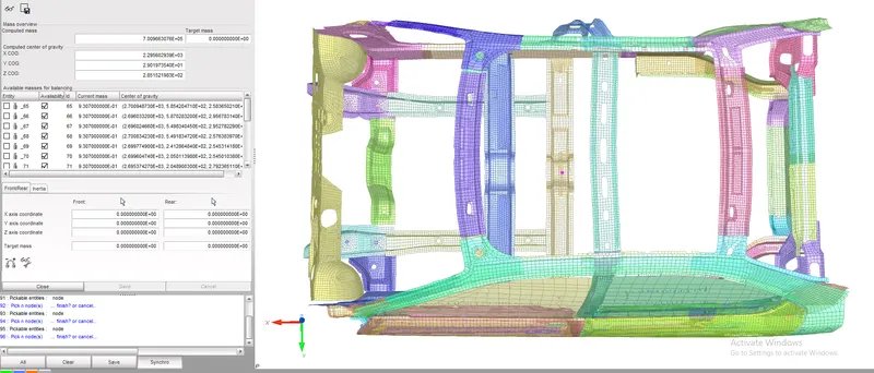
5. Mass balancing and COG adjustment - Mass addition is an essential factor that we need to assign before running the simulation. we have to keep the COG point in the middle of the model to attain good results. The center of gravity of any vehicle is the point that sums up the vehicle's mass in one central point.
The total mass is 166 kg and its COG cordinates are as shown in fig. But in this particular case ,the target weight is 700 kg. we have to attain 700kg and the COG point in the cross member. so we have to add 534kg mass in the vehicle and to get COG point in the cross member. the mass can be added as such that as COG point comes at cross member. create a mass with type 1 so that mass will equally be distributed to selected nodes. give the required amount of mass and select the area to be applied.
6. Initial velocity - Give an initial velocity to the vehicle - '/INIVEL ' define an initial velocity on a group of nodes. It does not require a function and does not vary with time. As required by the analysis, we provide an initial velocity of 35 mph or 15.6464 mm/ms to the vehicle in the lateral direction or Y-axis in this case.
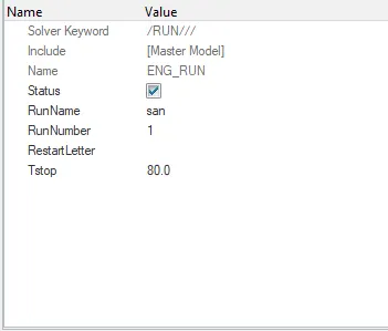
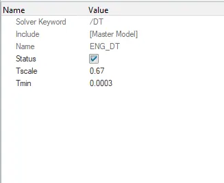
7. Providing timestep and mention run time - The time needed for information to cross the smallest distance in an element. the computed time step is compared to a minimum time step value and a scale factor is applied to ensure a conservative bond. the time step can be controlled by three types CST, DEL, STOP. we use CST type because elements are switched to small strain formulation to maintain the constant time step. it will add some mass to the nodes to increase density. so that speed of the sound waves varies. the nodal time step is calculated after the computation of all internal forces at each node. for creating time step solver -> engine keywords ->DT -> DT/NODA. we have time step as 0.0003 ms and scale factor as 0.67. and set run time to 80ms.
8. Create output request -
Sectional forces - To validate the flow of force from the B-pillar to the floor cross beams we create cross-sections of elements along this complete path and derive the normal forces acting on each section. Cross-section definition requires a local frame of reference and input of three nodes to further define the local skew. Also, a group of shells around the cross-section have to be input.
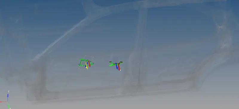
Intrusion point - We need to set up some intrusions points so that we will get an idea about the displacement of nodes in the impact area. we are selecting three points from the impact zone. B-pillar, hinge pillar, fuel tank are the region where the place we need to check the displacement. we need to set up the time history file so that we can extract the results after simulation.
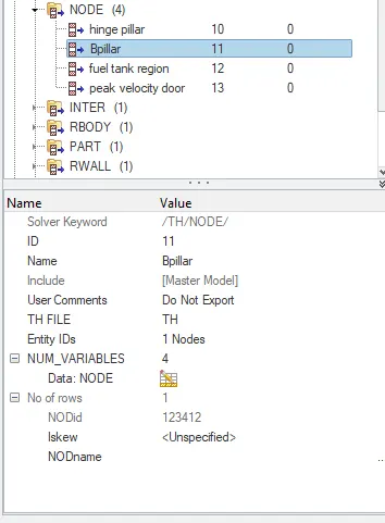
Peak velocity of inner node of the door - To receive this output firstly, we create a local fix skew at a location that has no motion relative to the rest of the vehicle. With respect to and input of this skew system we create a nodal /TH output block to receive the output of velocity among many other outputs.
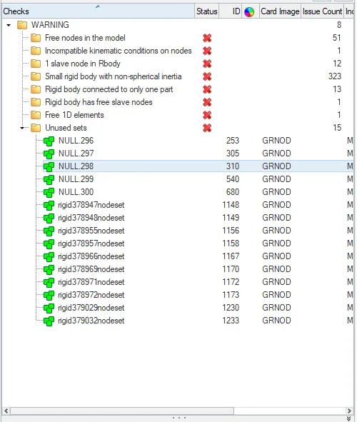
9. Run the Model checker - It checks for any and all potential issues that could terminate the solver when run. Issues such as incompatible kinematic conditions, under-defined or wrongly defined parameters, etc. can be corrected before running the simulation. We have no major errors after load case set up and only some insignificant warnings such as the presence of some free nodes that we created for reference. Such warnings can be ignored or dealt with using autocorrect tools.
RESULT -
Energy error and mass error -
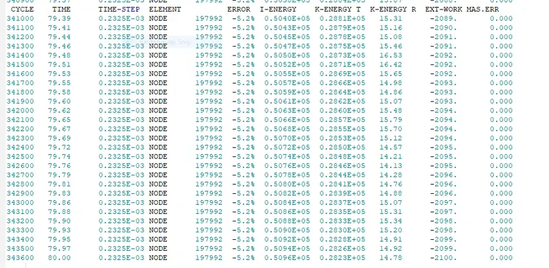
From above imagae the maximum energy error is -5.2% and mass error is zero which comes in acceptable range.
Any crash scenario involves huge changes in an object's inertia and leads to high dissipation of energy. This energy has to be absorbed by the car's structure before it reaches the passenger. This absorption of energy can only occur when the material deforms. Hence, the crash structure is designed in a way to crumple opposite to the direction of impact force and the remaining force is directed to the rest of the structure systematically.
Displacement -
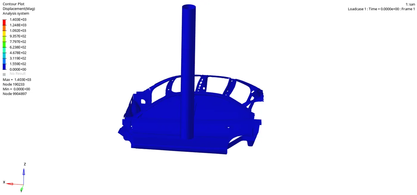
B-pillar on the left side receives maximum force since it impacts first, the deformation is more on the left side, components which are near to B-pillar receives maximum stress and deforms badly. It is only BIW structure crash, when it compares with a real-life crash the deformation will be different. The maximum displacement is 1403 mm.
Vonmises stress -
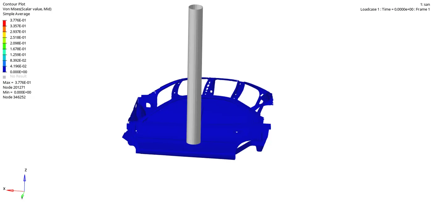
Maximum stress is 0.3776 found at node 201271. BIW structure achieves bad deformation, but in a real scenario, it won't be like this deformation. since there are components missing in the model, force is distributed to only BIW structure, so that it deforms badly.
Plastic strain -
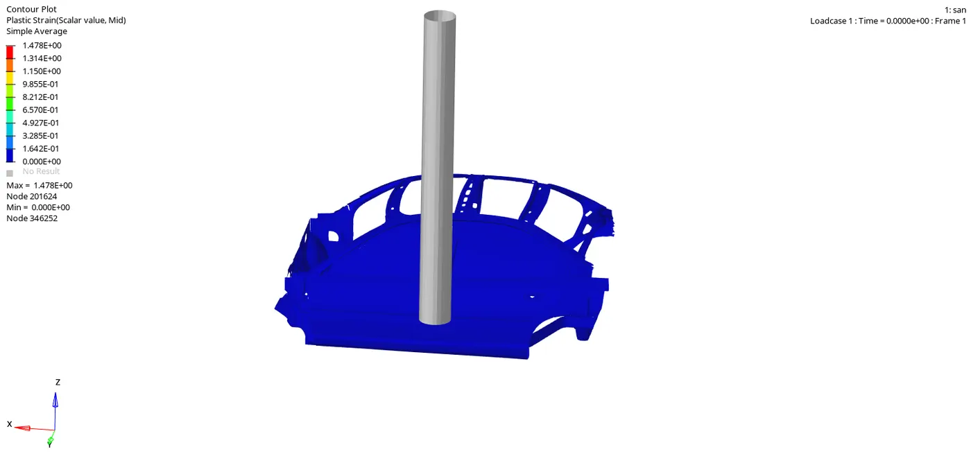
The plastic strain means that the element has deformed and absorbed the forces. So the animation shows that max plastic strain is formed in the region of the B-pillar and the Rocker attached to it which maybe means a good sign that this strain is not formed to the other side of the car.
Energy plot -
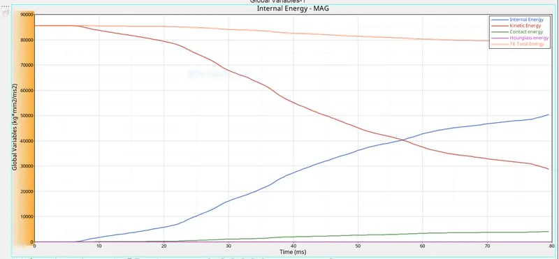
From the energy plot, kinetic energy reduces gradually after getting impact on the pole. internal energy increases when deformation starts after the impact. because kinetic energy is converted into internal energy after the impact. Hourglass energy is maintained at zero since we are using QEPH element formulation. the contact energy has been increased further because during deformation the components get contact with each other.
Intrusion point -
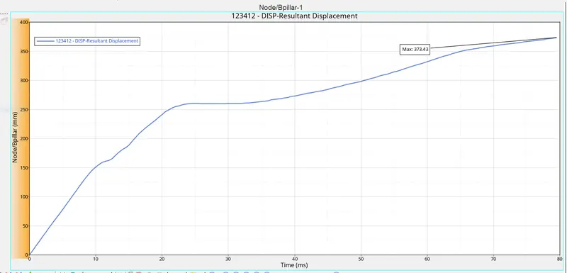
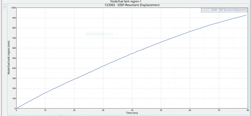
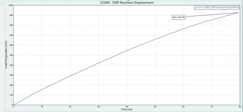
From the above graph, the maximum displacement is at the fuel tank, because B-pillar gets impacts on the pole and deforms near the pole, but the fuel tank region receives force and deforms badly by huge displacement. hinge pillar receives less force and deforms less than B-pillar. we need to add stability to the hinge pillar by changing material properties. because passengers will get hurt when the hinge pillar deforms badly like this in a real scenario.
So as seen from the graph plots the maximum amount of intrusion was found to be in the Fuel tank followed by the B-pillar and the hinge has the minimum amount of intrusion. The door has a minimum due to the structural member attached to it which has deformed less and so the less displacement for the hinge. But for the Fuel tank, the intrusion was more because there was no cross member that can reduce the amount of displacement.
Measure to reduce the fuel tank intrusion :
One simple step that can reduce the intrusion is to change some design aspect for the fuel tank that means a cross member that to some stiffer or with proper material can help in reducing the intrusion for the fuel tank. Material and design has to proper because the intrusion in the B-pillar was quite significant though it had the Cross-member.
Peak displacement of inner node of the door -
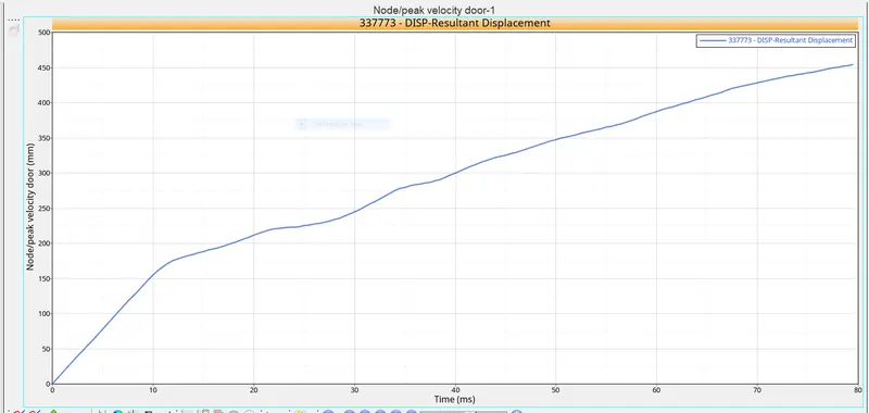
As we all know that whe the car hits the pole,1st impact will be the door and due to the deformation the inner portion of the door might hit the passengers incide the car and lead to the injuries.Hence it is important that the Peak velocity at the door region is to be calculated.
From the above graph, it shows that how much displacement happens on the inner side of the door during impact. The peak displacement measured on the inner side of the door is around 450mm.
Sectional forces in the cross member -
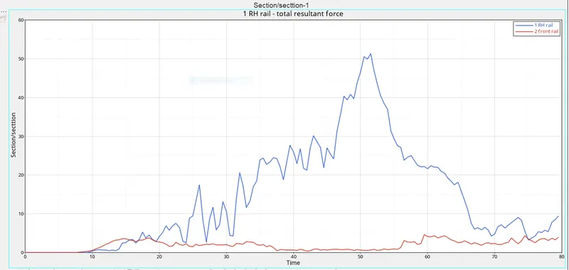
The maximum cross sectional force at Cross Member FR is 51.3 kN/mm at t= 52ms whereas The maximum cross sectional force at Cross Member RR is 4.62kN/mm at t= 59ms.One the Car hits the rigid pole,the deformation starts at the door section and the force is propogating from door to the rest of the car through B Pillar and Cross Beam.From the animation and the graph we can say that the force received at Both the section is not different.There is a variation in the amout of force receiving at the section with respect to time might be because of vibration during the crash.Both the sections are undergoing compression force.Once it reaches the maximume compressive force,the Door will push the cross member and thus cross member tending to start bending.Due to the bending of the cross member ,the force propogation through the section is decreases and the same we can see force is decrease in the section in the above plot.
Conclusion - When the car hits the pole at Bpillar, it begins to deform so some force is experinced due to the resistive force of the pole , thus the forces are ditributed to the hinge pillar, A pillar, fuel tank and cross members and they began to deform and this deformation causes crash enegry absorption and protects the occupants inside the car.
- As per the design the BIW structure works to dissipate the impact energy by crushing as well as it transfers it around the occupant chamber such that least damage si donme to the pasengers .