Assignment 7
Tutorial 9: Fast Running Model
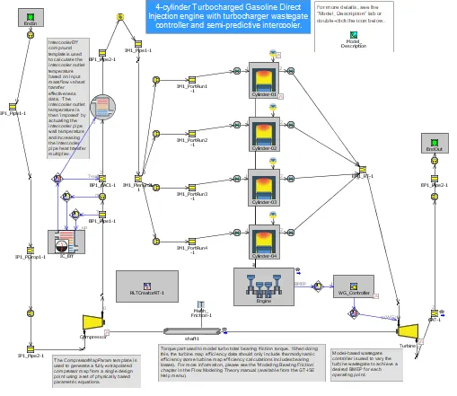
The given model is 4 cyl. gasoline direct injector, with turbochrager engine. For turbocharger friction model is also added, to model bearing friction of shaft.
To convert existing model model to FRM model. Go to Tool> FRM tags. In FRM tags, tags are already made. It is shown in following image:
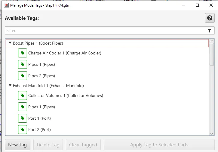
Here it is shown how many of subvolume will be grouped together. In order to do grouping FRM converter is used. Here in this model step wise conversion is done, also with the calibration. First exhaust manifold is grouped, with calibration to turbine outlet mass flow rate.
First exhaust manifold is converted. During the conversion one has to make sure the desired performance parameter are obtained. This is done once we click on Next (Calibration) button.
Once it is done GT ask for volume (By topology consideration) that represents the manifold or the circuit.
Similarly it is done for intake manifold, and other circuit. Final model is shown as follows:
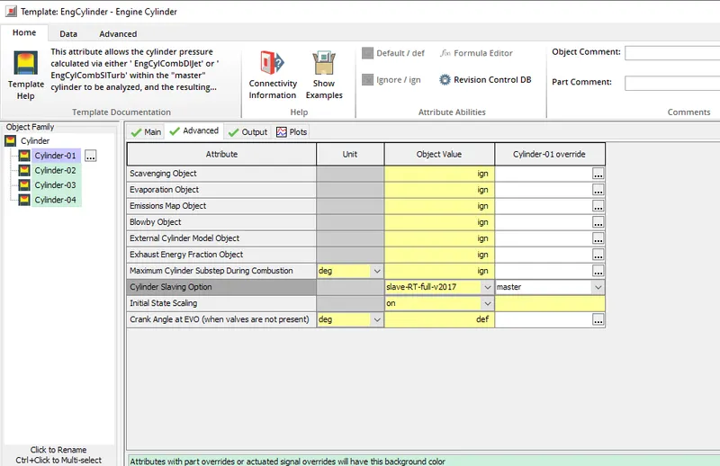
Further simplification is done by using cyliner mater and slave option. By use of cylinder slave option, the heat transfer and burn profile is copied to the slave cylinder, this reduces the computation time. Master cylinder in tutorial is as shown follows:
FRM Builder:
Following is the model created using FRM model builer for the given specification:
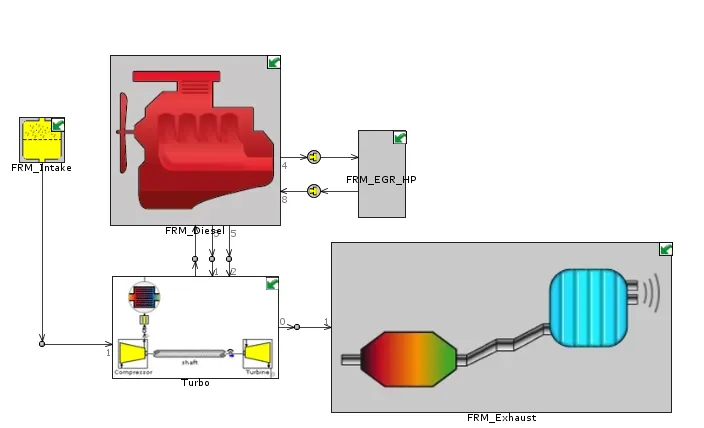
Following is the output:
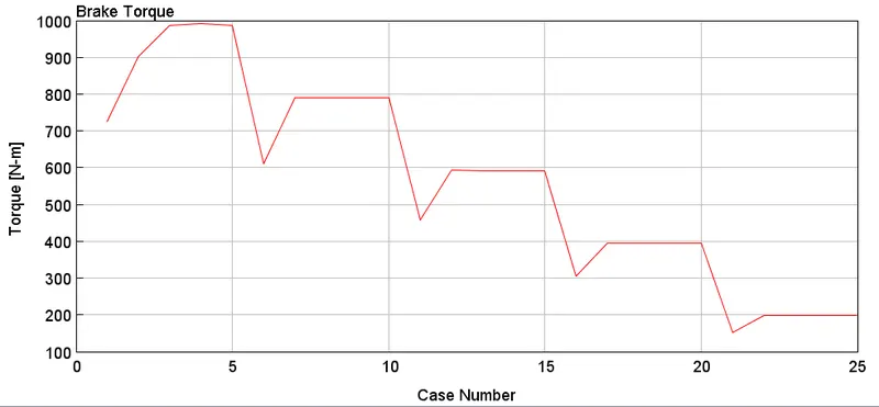
1. Torque curve:
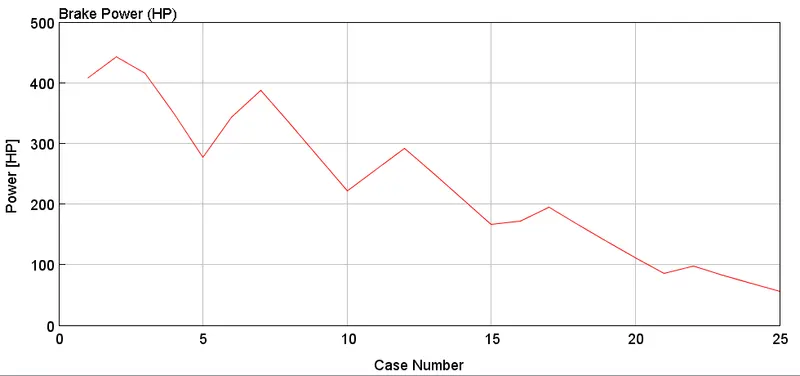
2. Power curve
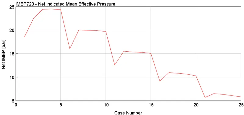
3. IMEP profile
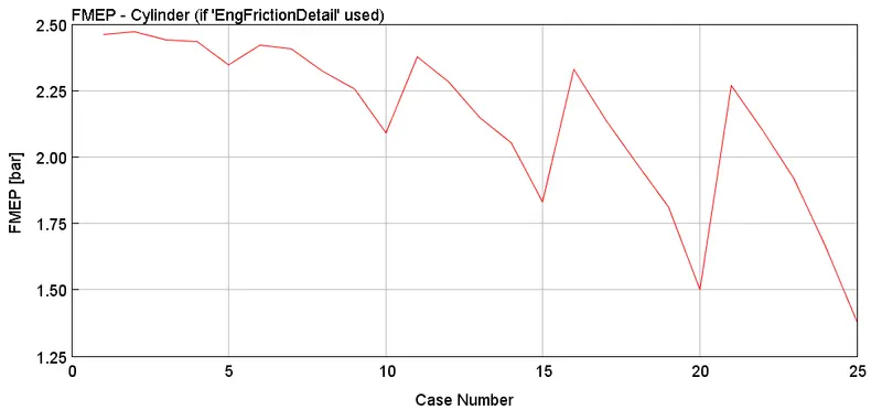
4. FMEP curve