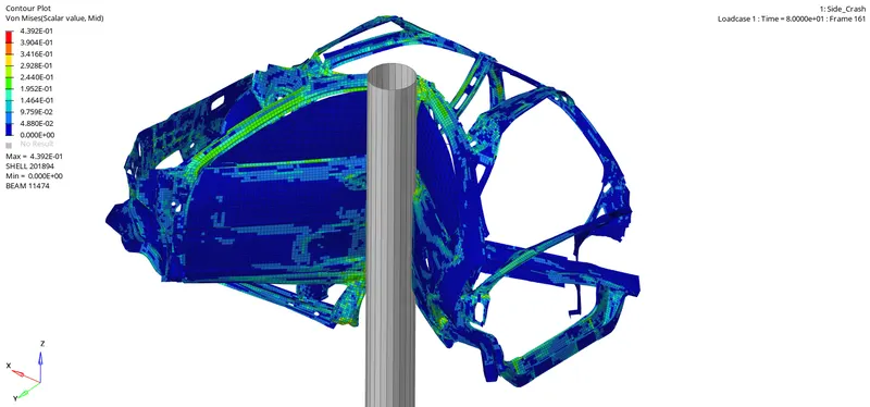
Side Car Crash test
AIM:
To perform the crash analysis for the given model and notify the energy difference.
METHODOLOGY:
- Importing the model.
- Checking the units and changes made if any.
- Create the required parameters and cross sections.
- Plot the graphs with different energies.
INTRODUCTION:
PROCEDURE:
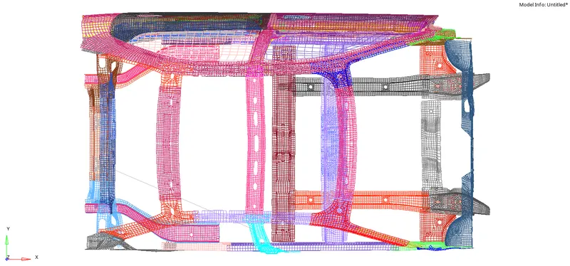
- Import the .hm file.
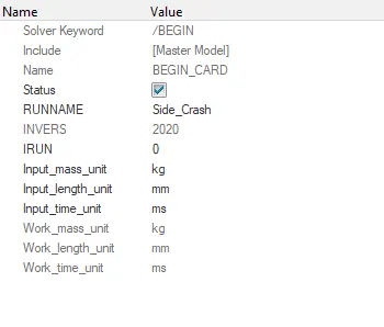
- Check the units in BEGIN _CARD.
- Units to be followed as “Mass(kg), Length (mm), Time (ms)”.
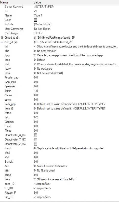
INTERFACE:
- New Interface is created and name it type 7.
- Change the card type to TYPE 7 and modify the necessary parameters.
- Select the Slave entities and Master Elements.
- Give the values of Istf (stiffness definition) as 4, Igap (gap/element option) as 2, Idel (Nodes and segment deletion) as 2, Irem_gap () as 2, Irem_i2 () as 0, stfac () as 2, Fric () as 0.2, Gapmin () as 0.5, Inacti () as 6, Iform () as 2.
RIGID WALL:
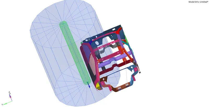
- Create a rigid wall by right click on tab area and RWALL and select ‘Cylinder’.
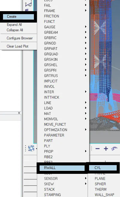
- Select the geometry type as ‘Infinite plane’.
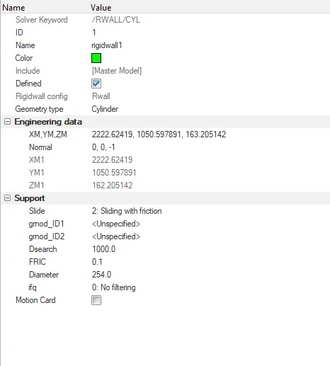
- Set the coordinates with selected base node for creating rigid wall.
- Select the Normal around the axis as per requirement.
- Give the Slide value as 2, Dsearch value as 1000, Fric Value as 0.1.
COG point:
- Check the COG point and modifies accordingly by adding node mass.
- Go to Tools menu, click on Mass Details and select the Mass,inertia and COG.
- A dialogue box pop up and check for the COG coordinates.
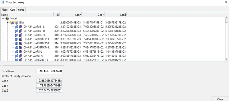
- Copy those coordinates and create a new node with those coordinates.

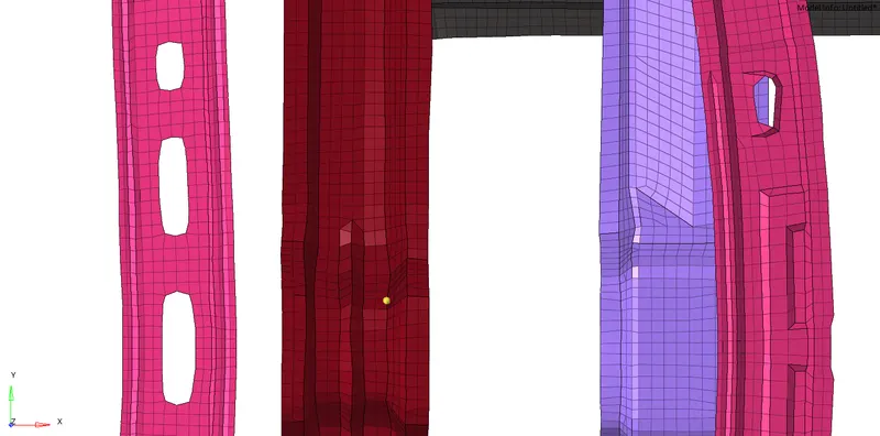
- If COG is not in required position the node mass is to be added.
- Right click on tab area and select ADMAS, a new card is created.
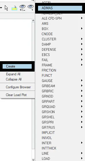
- Right click on gmd_ID and select create.
- Select the nodes for adding the mass with approx mass value.
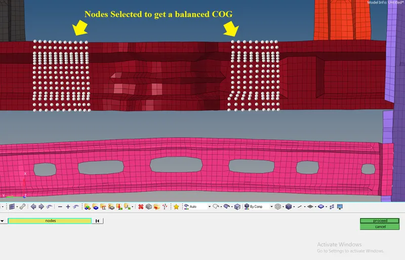
INITIAL VELOCITY:
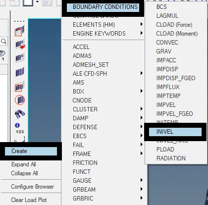
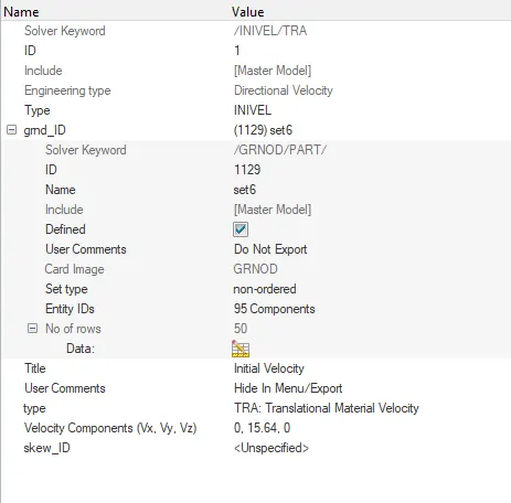
- Right click on tab area, select the BOUNDARY CONDITIONS.
- Select INIVEL, a new card is created.
- Right click on gmd_ID and select create.
- Select the displayed nodes and click proceed.
- Set the velocity value as 15.64 mm/ms (35mph as per question).
- Select the nodes for direction of velocity.
CROSS-SECTIONS:
- Right click on tab area, select SECT in create menu.
- New card is created, select three nodes for N1, N2, N3.
- Right click on gmd_ID and select create.
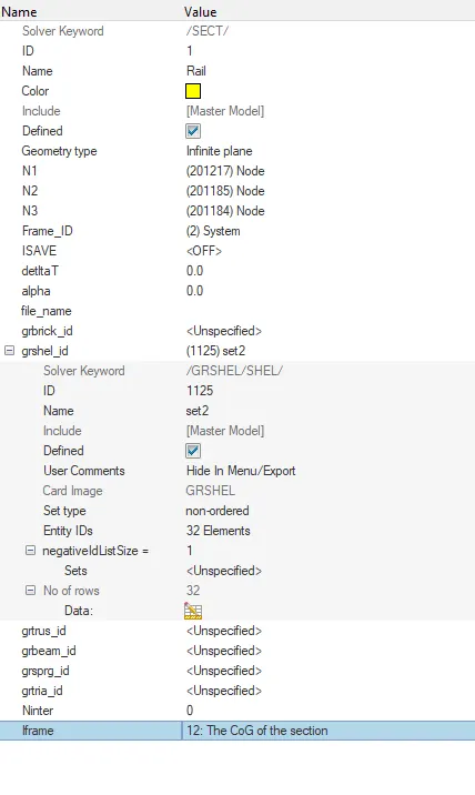
- Click on Entity ID’s, select the nodes for cross sections.
- Give the deltaT value as 0.1 and alpha value as 1.67.
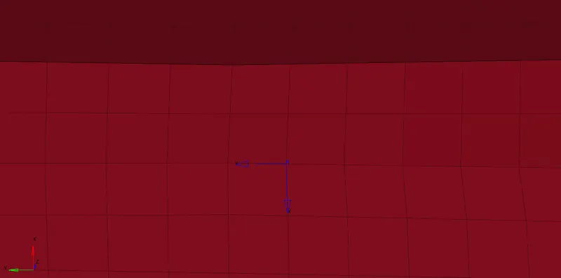
- Create a new Frame card in Solver Browser by right click in tab area.
- Select the three nodes for creating axis.

- Right click on grshel_ID and select elements for cross sections.
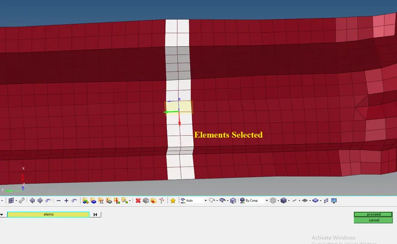
- Give Iframe values as 12.
- Follow the same procedure for cross sections at different locations.
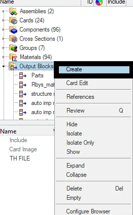
- To call out the cross sections created, click on Output blocks in Model browser.
- Create a new output block and rename it as cross sections.
- Click on Entity_ID and select all cross sections created.

PEAK VELOCITY:
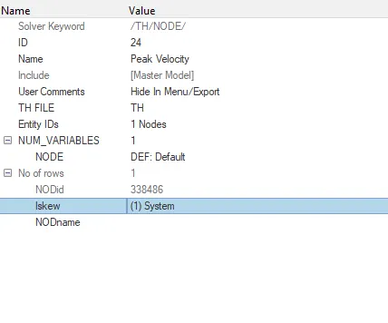
- Right click on tab area in model browser.
- Create a “Moving Skew”, a new card is created.
- Select the nodes for the axis.
- In Model browser, create a new Output block and rename it.
- Select the node on the inner door and also skew system.
- A new Output block card is created.
INTRUSIONS:
- Go to the Tools panel , click on numbers ,Select the nodes ,click on ID, give the node id as specified (given 66695, 66244) ,Click on display.
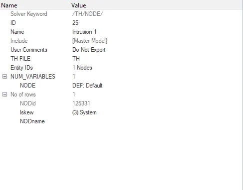
- Right click on tab area, click SKEW option, select MOV option , give a name to it ,select the nodes ( origin, axis, Plane nodes)
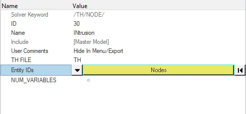
- Create a new Output block and rename it.
- Select the displayed node and skew system.
PENETRATION CHECK:
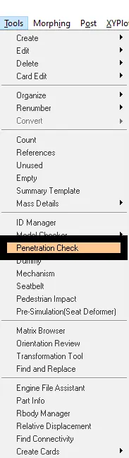
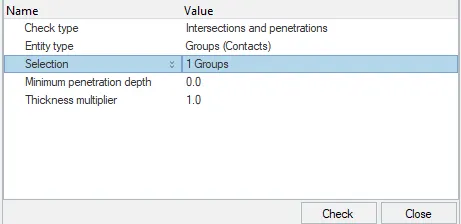
- Go to Tools, select penetration check.
- Select groups and proceed.
ERRORS:
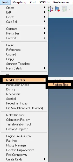
- Go to Tools, select the model checker.
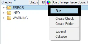
- Go to Solver Browser, right click on Error and select RUN.
- Clear errors if any.
RUNTIME & TIME STEP:
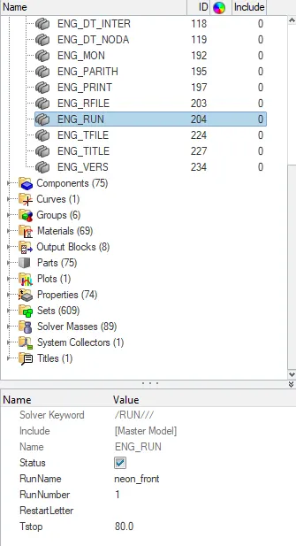
- Click on ENG_RUN in cards in model browser.
- Change the Tstop value as 80.
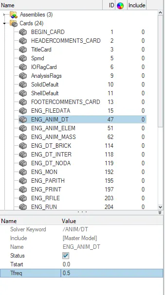
- Click on ENG_ANIM_DT and set Tfreq as 0.1.
OBSERVATIONS:
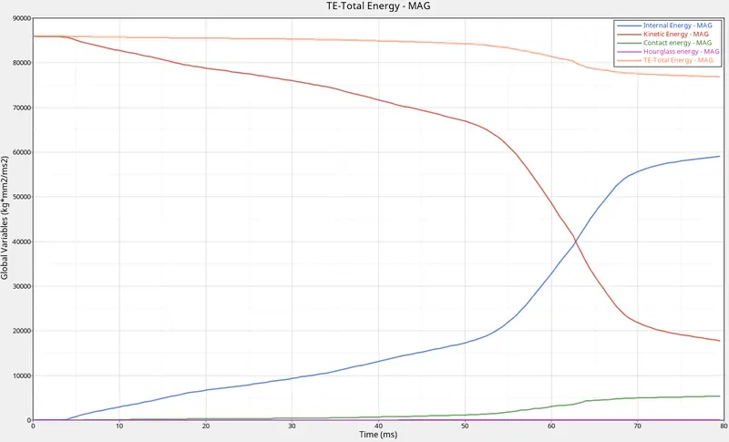
- Hourglass energy is constant as Ishell parameter is set to 24.
- Contact Energy is increasing slowly as the time goes.
- Internal Energy is gradually increasing and kinetic energy decreases gradually.
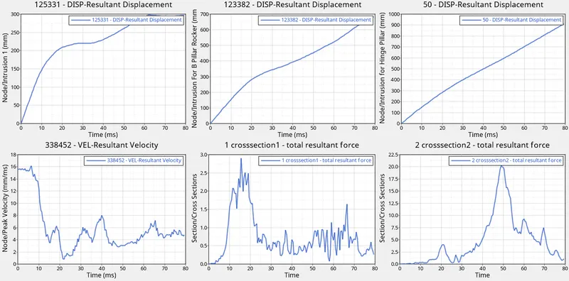
- The Intrutions of hinge pillar, B pillar and fuel tank are increasing gradually.
DEFINITIONS:
Centre of Gravity:
The center of gravity (CG) of an object is the point at which weight is evenly dispersed and all sides are in balance. A human's center of gravity can change as he takes on different positions, but in many other objects, it's a fixed location.
Accelerometer:
An accelerometer is a tool that measures proper acceleration. Proper acceleration is the acceleration of a body in its own instantaneous rest frame; this is different from coordinate acceleration, which is acceleration in a fixed coordinate system.
Peak Velocity:
The peak velocity is the highest velocity attained during the impact of an object at a particular time.
LEARNING OUTCOME:
Learned how to create
- Intrusions
- Interface
- Accelerometer
- Initial Velovity
- Rigid wall
- Cross sections.
- CoG
Learnt how to check errors and rectify it.
RESULTS:
The Simulation is completed successfully.
The Plotting of graphs is achieved successfully.
Energy Plots:
The energy plots are created between hourglass energy, Total Energy, Kinetic Energy, Internal Energy, and Contact energy versus Time.
Section Plots:
The plots for the cross-sections have different displacement values as the different components have different stresses acting upon it while performing a crash analysis.