Assignment 6-Frontal Crash Simulation Challenge
Aim
To perform frontal crash Analysis on BIW as for FMVSS Regulation
Introduction
A crash test is a destructive test usually performed in order to ensure safe design standards in crashworthiness crash compatibility for various modes of transportation.
The crash testing requirements can be divided into two
- Regulatory testing: FMVSS
- Consumers testing: NCAP
The regulatory tests provide answer to the question, wheather the car passes or fails. if the injury recorded in the dummy is less than the standard value then it is said to be passed.
Consumers testing will give a star rating based on the injury results. They also give ratings based on the individual component performance from the car.
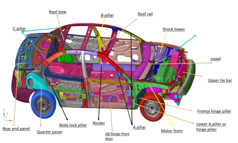
Objective
Frontal crash BIW
Check unit system and either follow [Mg mm s] or [Kg mm ms]
Create appropriate interface, friction 0.2 and recommended parameters
Make sure of no penetrations and intersections
Correct rigid bodies if any issues
Create rigid wall with friction 0.1
compare the model weight with the full scale 300 k nodes model and use added masses to reach target weight of 700kg while getting CG about the required range
Initial velocity 35 mph use model checker to ensure good quality
Time step :0.5 to 0.1 microseconds and run time 80 ms
Use model checker to ensure good quality
Output required
Sectional force in the rail at location of indicated nodel 174247
Axial force received on the rails from bumper
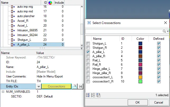
Shotgun cross sectional forces
A piller cross section
Acceleration curve received on the accelerometer at base of B piller(on B piller rocker)
Intrusions on the dash wall 66695, 66244
Procedure
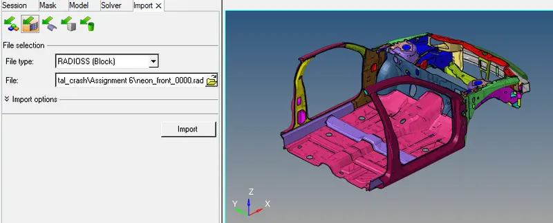
The first step is to open the HyperWork software and in the interface it will ask to select the a solver, here we select Radioss as a solver. Then we need to import the model of _0000.rad file as shown below
- Check unit system and either follow [Mg mm s] or [Kg mm ms]
For checking unit system go to Model->cards-> BEGIN_CARD as shown below
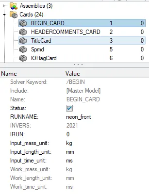
Since the unit followed is [Kg mm ms] we will follow the same unit system throughout the analysis.
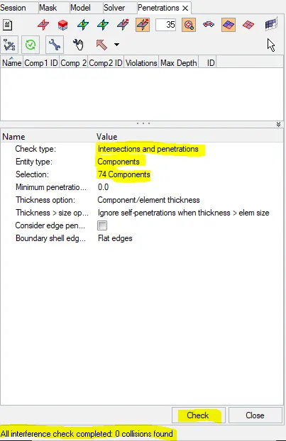
- Make sure of no penetrations and intersections
Go to Tools-> penetration checks-> all the components than click on check we can see below there is no any intersections and penetrations.
- Create appropriate interface, friction 0.2 and recommended parameters
Go to model browser->groups->create-> select type 7 and enter recommended parameters with friction factor of 0.2
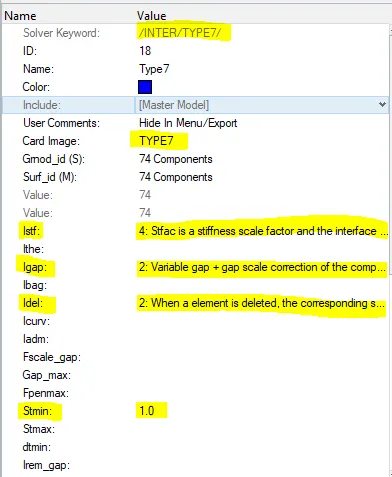
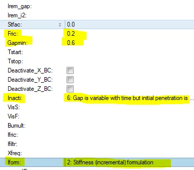
- Create rigid wall with friction 0.1
Go to solver model->create->Rwall and select plane
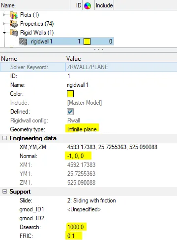
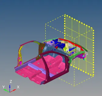
We can see the Rwall collector has formed automatically in the model browser with all assigned parameter.
- Initial velocity 35 mph
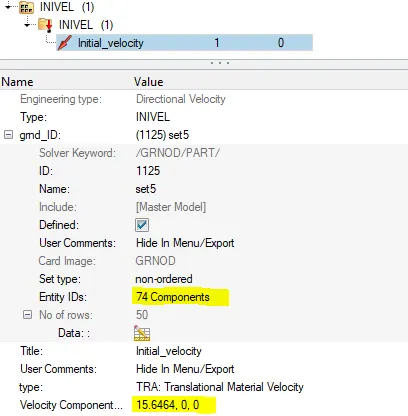
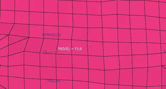
Solver browser-> create-> boundary condition->INIVEL
Enter the value of 15.6464 mm/ms which is equal to 35 mph.
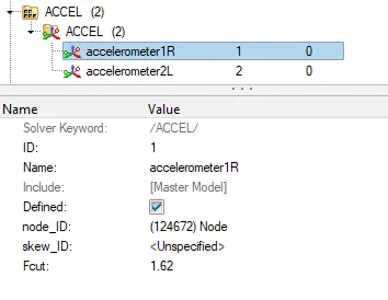
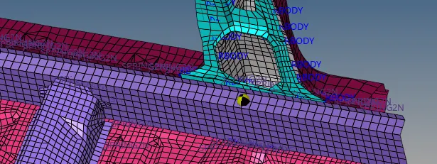
- Accelerometer: Acceleration curve received on the accelerometer at base of B piller(on B piller rocker)
solver-> Create-> ACCEL, select the node where you want to apply
- Sectional force in the rail at location
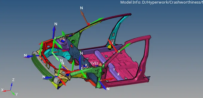
we have to obtain results for the defined cross sections. for that first we have to create frame. Go to Solver -> create->frames->mov->than create the system(by origin, x-axis, XY plane) as shown below
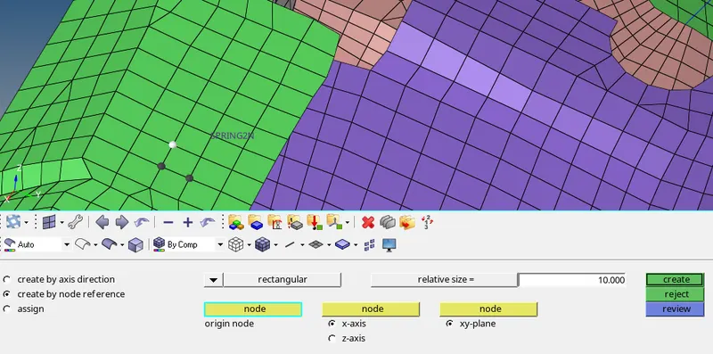
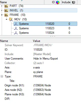
Then go to solver-> create ->SECT->Frame_ID->deltaT and alpha and grshel_id
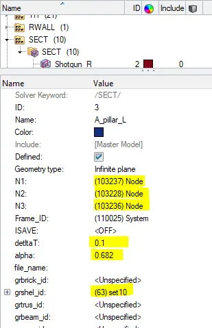
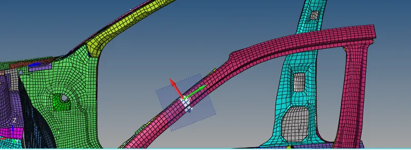
Similarly, we create the moving frames and sections at desired areas on the left and right of the model as shown below.
For output request go to model->output blocks->right click on output blocks and create rename and enter entity IDs as crosssections than select as per required.
- Intrusions on the dash wall 66695, 66244
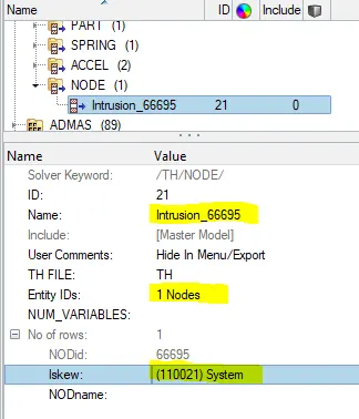
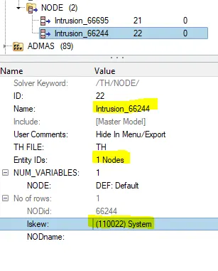
First of all we have to create local coordinatein skew collector of solver browser
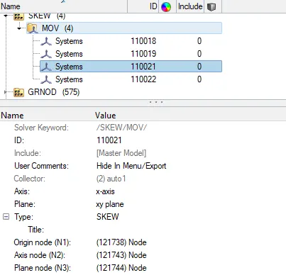
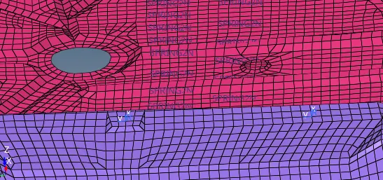
fig:-skew location
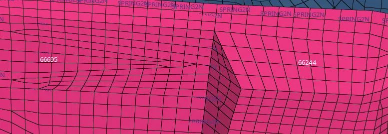
fig:-nodes where we want intrusion
Go to model->output blocks->create-> Rename as intrusion_66695 and select the node where we want to find intrusion in our case at 66695 node id as shown below
- Compare the model weight with the full scale 300 k nodes model and use added masses to reach target weight of 700kg while getting CG about the required range
first of all we will check mass and CG of the vehicle in HyperCrash for better visualization.
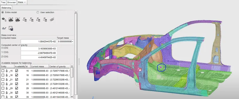
In the above figure, we can see the mass of the vehicle is 188 kg and CG of the vehicle (as shown above). In general, the Cg of the vehicle is somewhere just behind the driver's seat. so in order to get the required CG location , we will be adding mass for getting at required location CG. the total mass of the vehicle is 700kg. In Hypermesh, under solver browser we will right click and navigate to create->ADMAS. In ADMAS panel we will specify the required mass to selected nodes amd mass types as 1 as shown below.
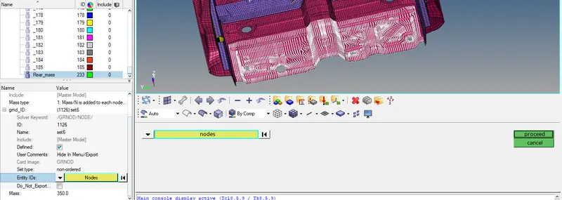
After adding mass at different location of the vehicle. Go to Tool->Mass details-> mass Cog inertia, here we can see total mass of the vehicle and CG of the vehicle.
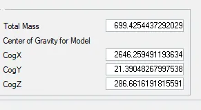
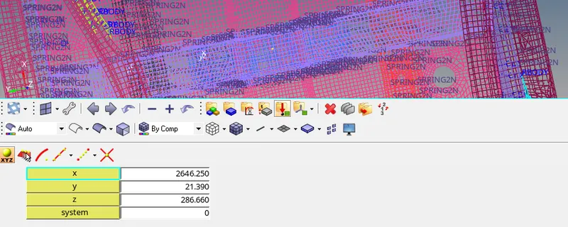
Go to Geometry->node-> create by adding CogX, CogYand CogZ value we can see the CG point of full vehicle as shown below.
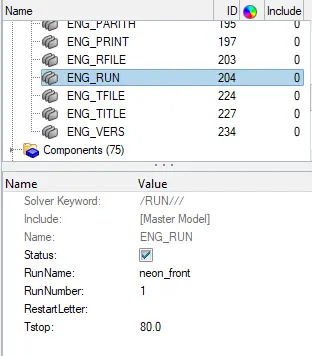
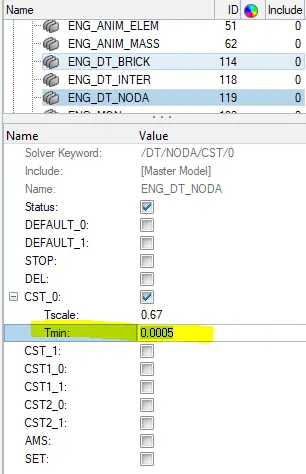
- Time step : 0.5 to 0.1 microseconds and run time 80 ms
To check these paramter in Hypermesh, we will navigate to Cards under Model browser to check the run time. and enter the value of run time and Tmin as shown below.
- Use model checker to ensure good quality
To check the qaulity of the model in Hypermesh, In main menu bar we will navigate to Tools->Modelchecker->RadiossBlock, this will open a new model checker browser.
In the browser, we will run the checks command which is top right side. after running the checks, there is no error in the model and only warning are present, warning can be ignored.
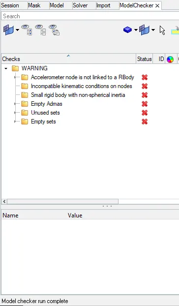
now we can proceed to run the simulation.
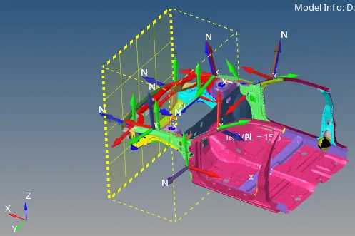
Final set up model
Simulation
To run the simulation, Go to Analysis->Radioss. In option type -nt 4 which means assigning the task to 4 cores in the system, to perform the simulation faster. Its depends upon the process of our computer(it has a quad- core processor, than it will take as 4. if the system has an octa- core processor than it is taken as 8). nt means number of threads, finally click on Radioss in order to run the simulation.

After clicking Radioss we get the solver window as shown below, after few minutes Radioss does the job and click on Result
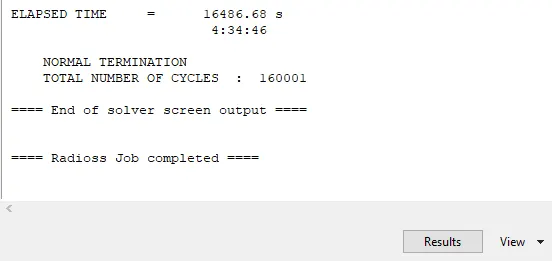
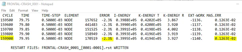
Now its time to energy error and mass error check and this is done by analyzing the radioss engine output file. it can be accessed from the same directory as the starter and engine file and it ifile extension by _0001.out open this file in notepad as shown below.
After Clicking on result it will switch to Hyperview window.
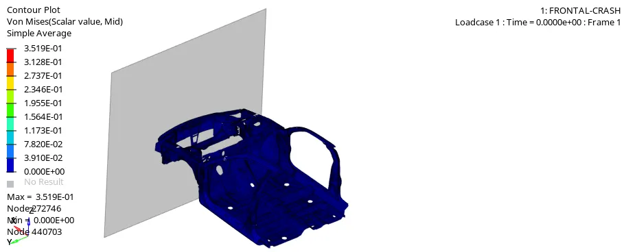
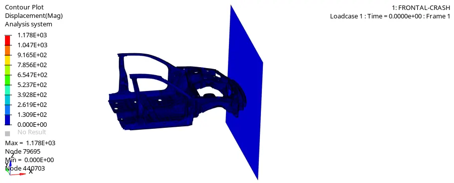
Now to simulate the animation click on contour option in the toolbar. change the result types to von mises stress and change average method to simple click on apply. Animation will start as shown below
HyperGraph 2D
Energy
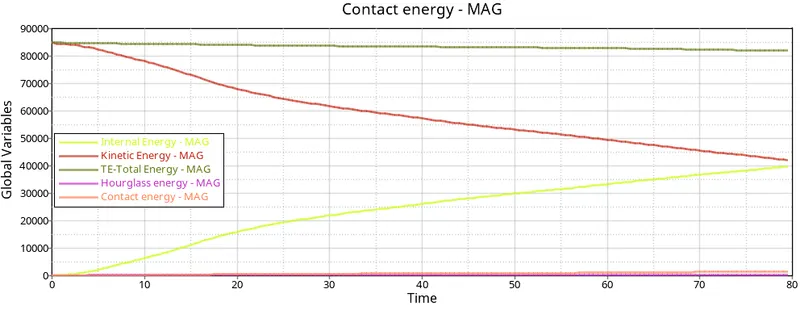
From graph, the Kinetic energy decreasing gradually so that while impact take place, than it start to deform so that the strain or internal energy increasing hence total energy of the system is balanced but there are some crests because of the contact energy.
In this hourglass energy is constant due to QEPH element formulation and recommended parameter.
Section force
Section force tell us how much forces is passong through a particular section(cross section).
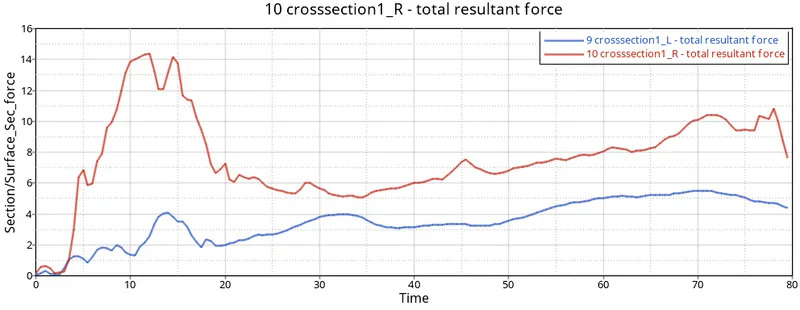
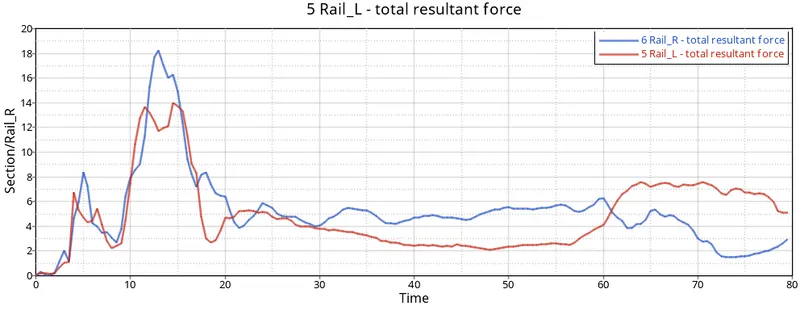
Axial force received on the rails from bumper
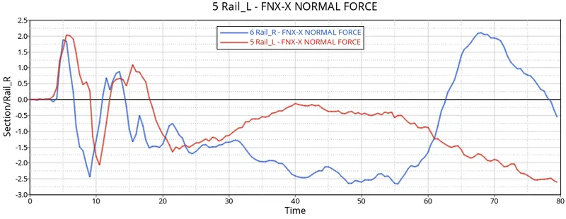
Axial force occur at the bumper as we can see after 5ms there is a sudden rise in the force of the whole bumper.
Shotgun cross sectional forces
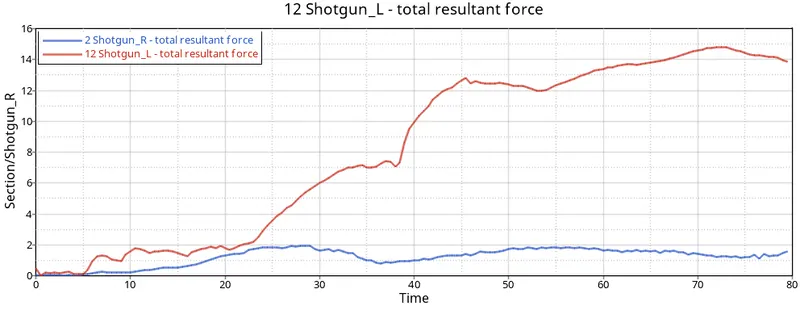
from the above graph we can see that initially the resultant forces experiences on the Left side is more than Right side of the shotgun in vehicle and increases continousely.
A piller cross section
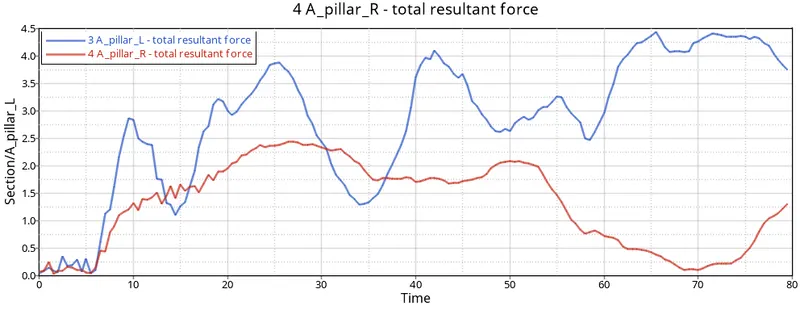
From the graph we can see that the resultant forces experenced on the Right side is less than Left side of the A pillar.
Acceleration curve received on the accelerometer at base of B piller(on B piller rocker)
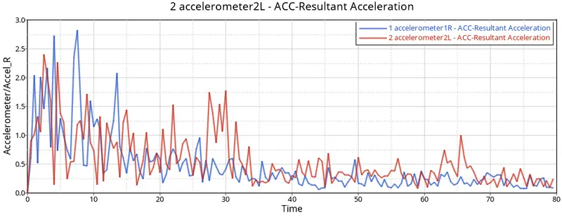
We know that accleration is propertional to velocity. change in velocity leads to change in accleration, once bumper and frontal portion deforms crash crash increases so accleration increases. maximum accleration observed on left and right side is 2.4 m/s^2 and 2.8 m/s^2.
Intrusions on the dash wall 66695, 66244
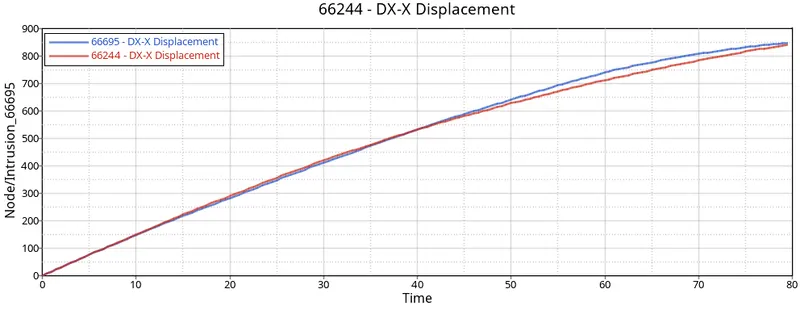
The intrusion force increase with respect to time as it is deforming progress.
Therefore the force is directly distributing to the driver legs that means it is not safe for the driver at the brake padel Hence AirBags must be used in vehicle.
The maximum displacement of the vehicle is 950 mm.
Rigid wall force
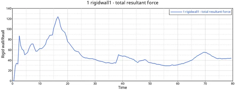
from the graph, we can see after some span of millisecond the car bumper hits to the rigid wall and impact begins
Around 17ms the maximum force is 122 KN on walls.
Learning outcomes
Able to understand
- Element properties formulation
- Material properties and Laws
- Interface modelling
- Kinematic condition and Boundary condition
- Load defination
- output request
- Method to increase simulation speed
Conclusion
The neon car model is impacted on a rigid wall to study the frontal crash scenario of the vehicle. The location of the Cog is as per the real life scenario which play an important role in frontal crash analysis. The energy and mass error are -2.3% and 0.1263% which is acceptable.