Assignment 6-Frontal Crash Simulation Challenge
Aim
To do the model check and simulate Frontal Crash of BIW of a car, And extract, Plot Forces, Stresses and Energies behavior on the BIW Structure and plot the Acceleration with the Accelerometers and Intrusions on the BIW
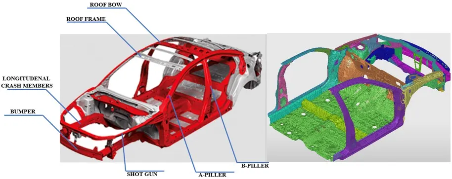
Crashworthiness Analysis
Crashworthiness Analysis is a multidisciplinary field focused on evaluating and improving a vehicle's ability to protect occupants during a crash. it involves understanding the mechanics of colliding structures, human body dynamics, and the effectiveness of restraint systems like seatbelts and Air bags. The goal is to minimize Injuries and fatalities by optimizing Vehicle Design.
Objectives of the project
- Check unit system of the model.
- Create appropriate interface with friction 0.2 and recommended parameters for the interface.
- Make sure of no penetrations and intersections.
- Correct Rigid Bodies if any issues.
- Create Rigid wall with Friction 0.1.
- Compare the model Weight with the full scale 300K nodes model and use added masses to reach target Weight 700kg while getting CG about the required range.
- Initial Velocity 35 mph.
- Time step 0.5 to 0.1 microseconds.
Output Requests
- Sectional force in the rails at location of indicated node 174247.
- Axial Force received on the rails from bumper.
- Shotgun Cross sectional forces.
- A pillar cross sectional forces.
- Acceleration curve received on the accelerometer at base of B pillar.
- Intrusions on the dash wall 6695 66244.
STEP1
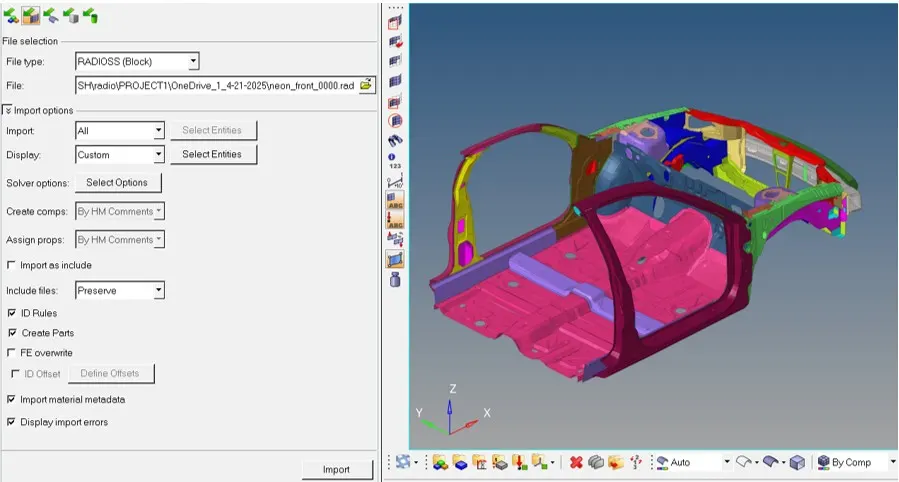
Import
Import the Finite element model in to Hypermesh and Hypercraash in to RADIOSS profile by using Import option as shown below
STEP2
Units System
check the unit system used in the model from the begin card in solver or by opening the starter file in Notepad

Kg, mm, milli seconds units are used through out the model and in the output results.
STEP3
Check for free parts
After checking the unit system check for the flying and unconnected parts in the model assembly
Hypermesh --> Tools --> Find connectivity --> select components(All) --> Check-->Isolate parts
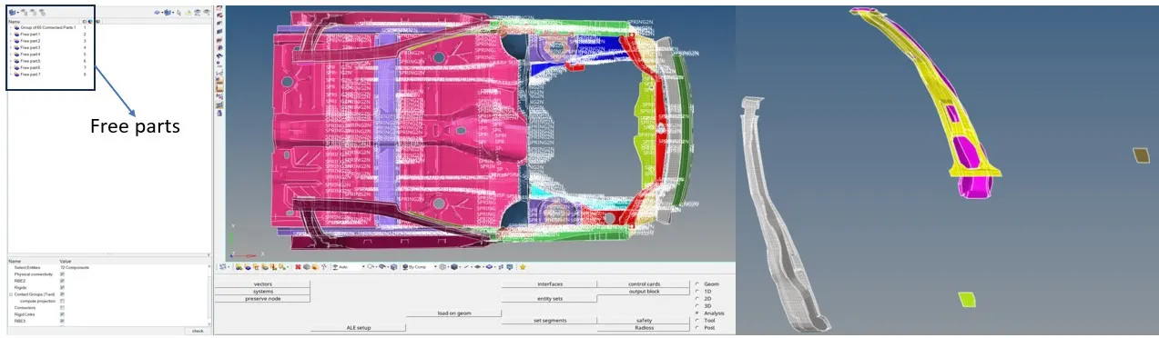
Found 8 flying parts in the assembly which are missing connections and these parts are need to be connected by spot welds or spring or rigid elements.
I am using spring elements to connect the parts in Hypermesh
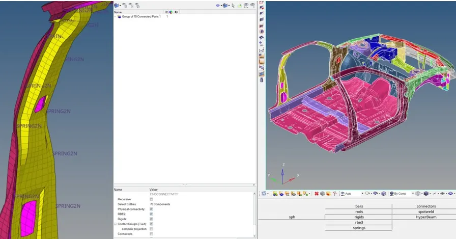
All the flying parts in the assembly are connected no free parts found in the connectivity check.
STEP4
Create Interface between the parts with recommended interface contact properties to the parts which may come in contact each other or self intersection.
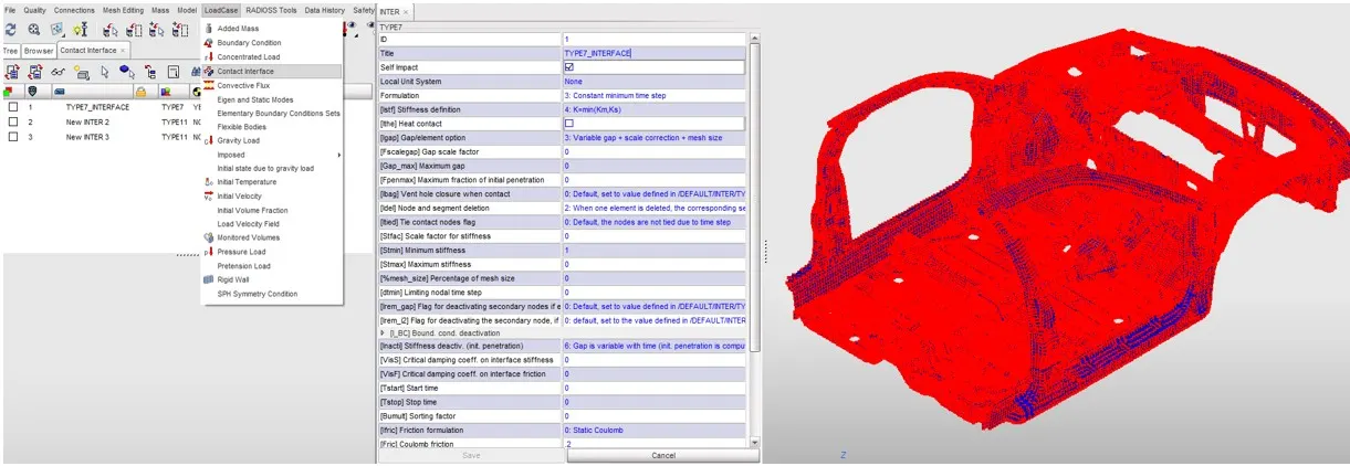
Type7: Surface to Surface contact
Type7 interface is created for whole model as Type7 interface has the ability to interpolate self intersection and recommended properties for type7 contact is
Igap: 2or3 set variable gap to take into account the true distance between parts.
Inacti: 6 Remove initial penetration where possible elsewhere reduce to less than 30% of the defined gap value and adjust the gap with inacti.
Istf: 4 Set Stiffness of interface based on softer of master and slave.
Idel: 2 Remove slave nodes in the contact because of element deletion.
Iform: 2 Sliding forces are computed using stiffness parameter of the interface.
Gapmin:0.5 specify minimum thickness of the model to avoid numerical issues typically half the the thickness of part.
Stmin: 1Kn/mm specify minimum stiffness in the contact to avoid too soft contact.
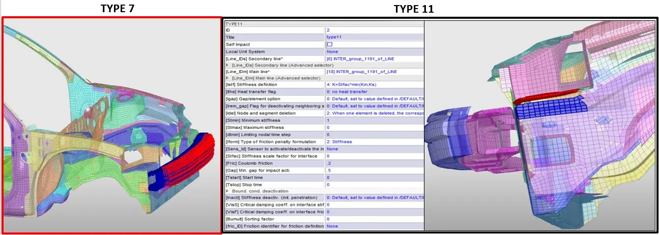
Type 11: Edge to edge contact
The properties of Type11 contact is same as type7 only the difference is this contact is used to create edge to edge interface
STEP5
Penetration and Intersection check
Hypercrash -->Quality-->Check all solver interfaces-->check
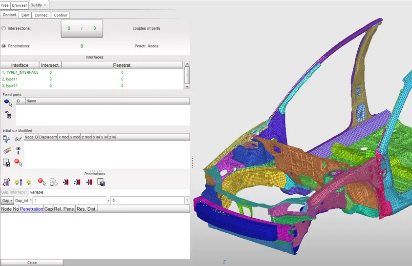
Found no intersections and penetration of the elements in the interface.
STEP6
Mass Addition & COG correction for Stability
Compare the model Weight with the full scale 300K nodes model and use added masses to reach target Weight 700kg while getting CG about the required range.
Mass is Added on the frame so as to match near to 700 kg is the location as in the below picture
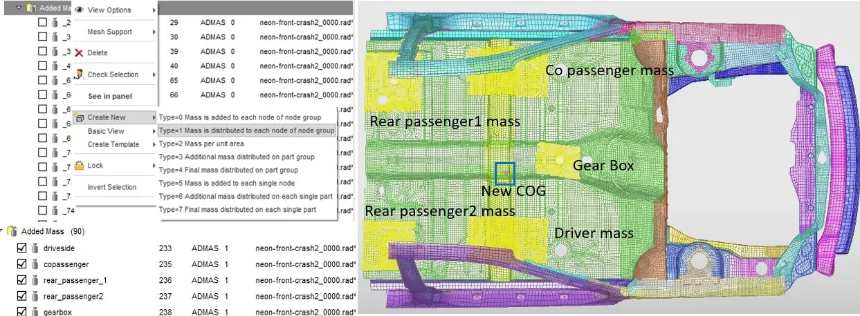
And Weight is added in such a way that to move the Center of Gravity(COG) to the required location and COG is moved to required location for the stability the body as shown below and meeting weight in the objective
STEP7
Rigid Wall Creation
Hypercrash-->Load case--> Rigid wall-->plane-->select node
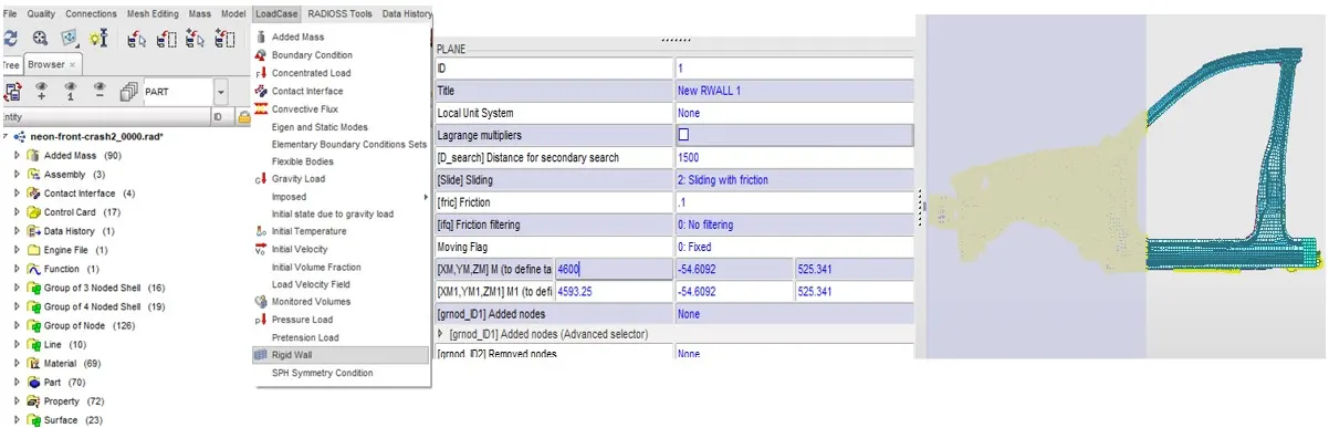
Rigid Plane Wall is created with friction of 0.1 as suggested in the objective with slave search distance of 1500mm
STEP8
Apply velocity to BIW, Create Sections and Accelerometers and intrusions
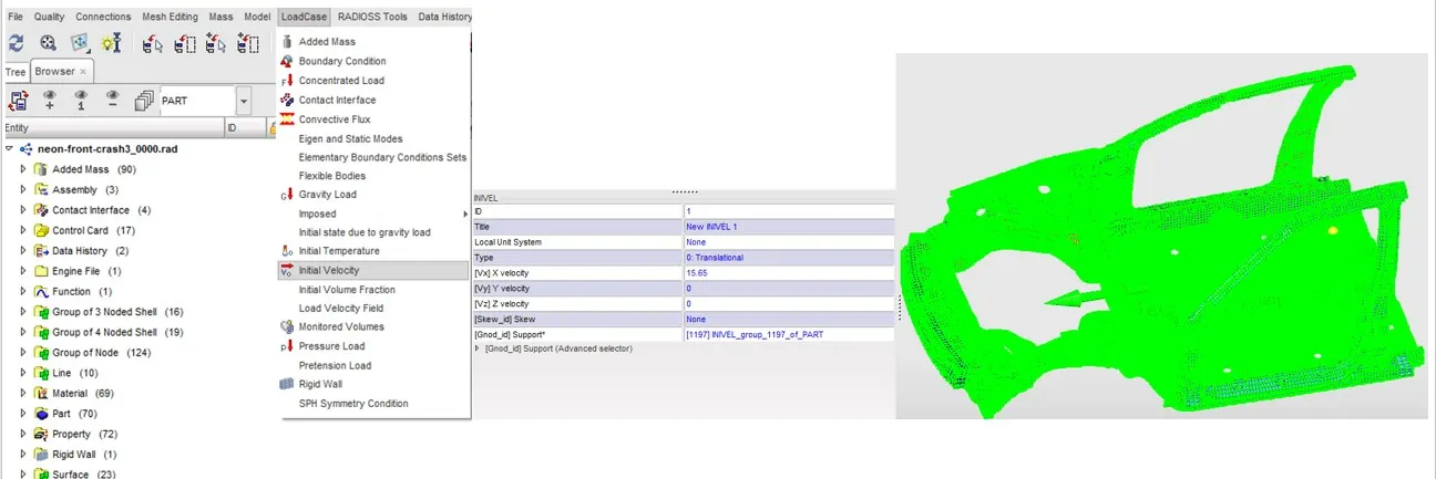
Hypercrash-->Load case--> Initial velocity-->Translational-->select direction
Apply the Initial velocity of 35 mph(15.65 Kmph) to the BIW for frontal crash in to the plane Rigid wall
SECTION CREATION
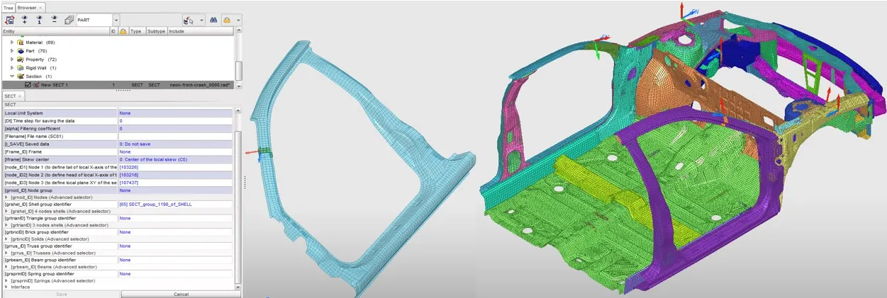
Sections are created on the parts i.e. A-Pillar, Fenders, Crash Rails for the study of forces acting on the parts in the Time history plots this is done to check for energy transfer
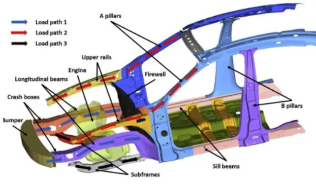
As in above picture the load will be transferred in these parts to further study the forces and energies passing through them section are created as below
Hypercrash-->Create New-->Section-->Select Nodes to create movable Skew Frame-->select Elements of study
Accelerometer
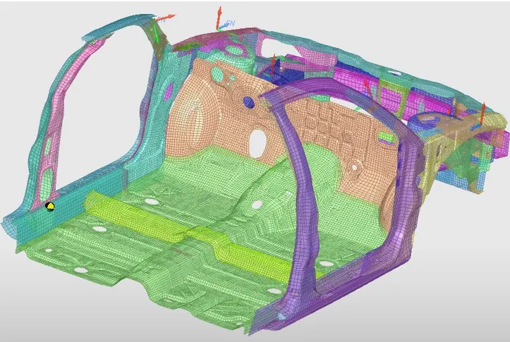
Accelerometers are the devises that measure the vibration, or acceleration of motion of a structure, they have a transducer that converts mechanical force caused by vibration or a change in motion into an electric current using piezoelectric effect. In this model, I have created two Accelerometers on the Rockers just beneath the B-Pillar of either side
Intrusion
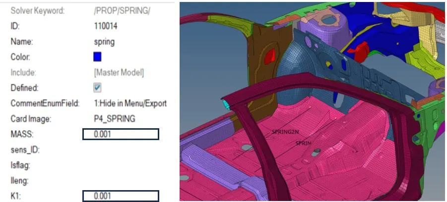
Springs are generated to study the intrusion (forces inside cabin causing deformation)
Mass of the spring and Stiffness of the spring are very negligible so as the spring mass and Stiffness will not cause any effect on the deformation
mass of the spring(m) is 0.001 kg Stiffness(K) 0.001 KN/mm
STEP9
Apply the Time Step and the minimum time to Run the simulation for the crash.
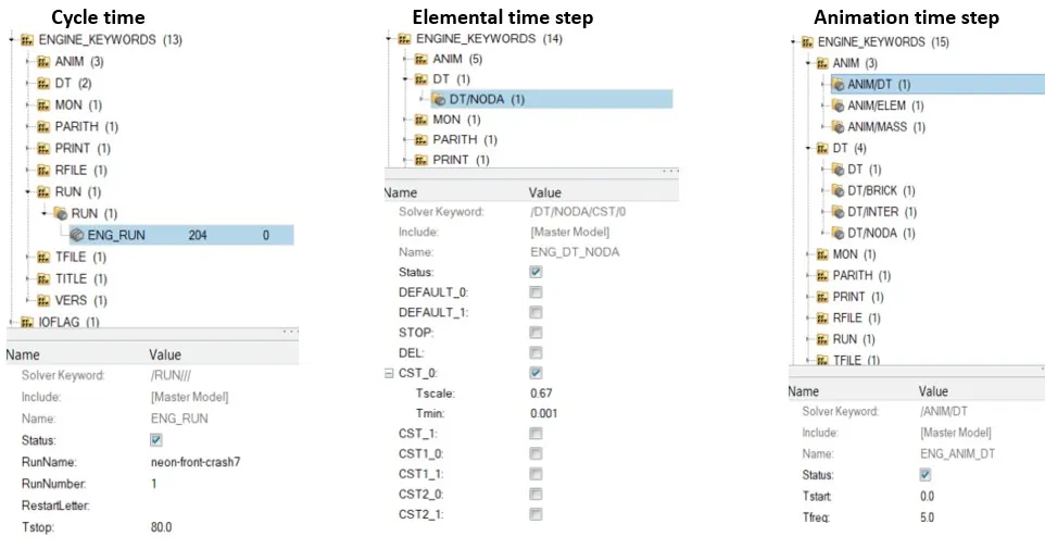
Cycle Run Time: cycle time is the time which the simulation need to run for this frontal crash simulation 80ms is the cycle time.
Elemental Time step: The time increment to advance the solution for this simulation elemental time step is 0.1ms.
Animation Time Step: Animation Time step is the Time for which the animations of the simulation need to be extracted for the frontal crash analysis the Animation Time step is 5ms
STEP10
Output Requests
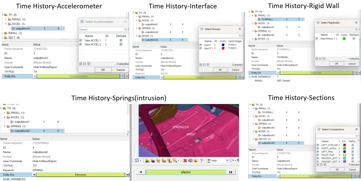
To attain simulation and trends of Energies and forces acting on the BIW body in the Crash, need to request the solver for some outputs these are Time History(TH) outputs.
Global variables: Internal Energy, Kinetic Energy, Total Energy, Rotational Total Energy, Total Translational Energy, Contact Energy, Hourglass Energy, Global External Work, moment in X,Y,Z directions
"All the Energies plotted will help to calculate the Energy error"
Other Time History plots
Velocity, Energy, EPSP(plastic strain), Vonmises, DMASS, DT, Global Spring energy & Sectional forces.
STEP11
Model check Run
Run the model checker to check for Errors and correct them for smooth run of the simulation
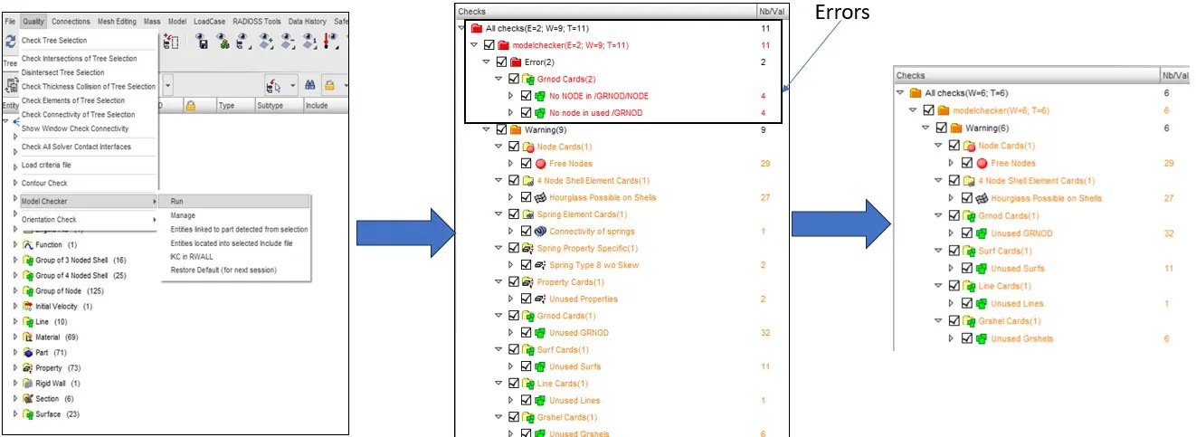
Found Unused sets and properties in the model we can delete unwanted Things deleted all unwanted properties elements and sets the model check show no errors
STEP12
Dry Run
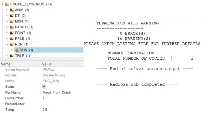
Perform a Dry run so that we can find any missing errors that was not found in model checker by putting the run time 0.
STEP13
Full Run and Result Debugging

Ran the Simulation for different Time steps
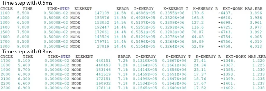
From the above results with the Time step 0.5ms there is Energy generation of 14.5% and mass addition of 4% to maintain constant time step with scale factor of 0.67 which implies bad results for the simulation
Similarly for 0.3ms time step the Energy error percentage is 7.1% i.e. energy is created in the simulation and mass addition at the nodes is 1.23% so as to maintain constant Time step. And the energy created and nodal mass addition is above the acceptable limit. This time step results are not acceptable.
More the energy created more the work done which leads to unreliable deformation and results.
By Further reducing the time step to 0.1ms the Results are as shown below.

From the above results with the Time step 0.1ms there is Energy loss of 2.4% and mass addition of 0.02% to maintain constant time step with scale factor of 0.67 which implies Good results for the simulation as the results are with in the acceptable limits.
In explicit analysis a larger time step increases numerical integration errors especially for high strain rate events, contact impacts, Nonlinear material behavior
Smaller Time increases cost but captures stress wave propagation, smoother contact interface and element distortion.
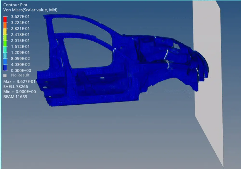
The Maximum Von Mises stress is observed 3.627e-01 GPa and observed Stress flows from bumper to whole BIW body.
The different Energies acting due to the impact are studied from plotting the graphs (time history plots) which were requested in the output requests which was done by the radioss and all these plots are written in T01 file
We need to open the T01 file in Hypergraph2D as shown below

Global Variable Time history Plots
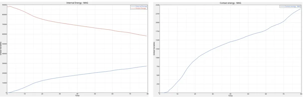
Kinetic & Internal Energy
As The body initially moves with a velocity it contains Kinetic energy in the car body, when the car body comes in to impact with the rigid wall the kinetic energy will converted to other forms of energy and major energy is converted Internal Energy
As shown in the above plot as the kinetic energy decreases the internal energy increases.
Contact Energy
contact Energy is the energy formed when one element tries to intersect into other element, from the penalty method the intersection is avoided by generating Stiffness and this will create contact energy
From the contact energy plot the contact energy keeps on increasing as the velocity is imposed on the body it tries to crush the body in to rigid body which leads to more contact energy.
Hourglass Energy
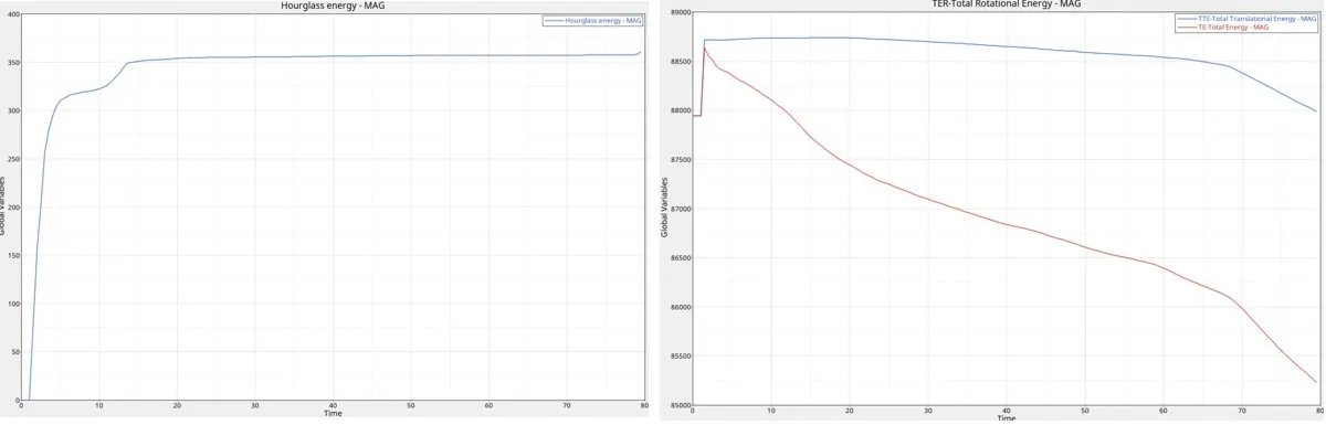
Hourglass energy refers to non-physical, zero energy deformation mode that occur in under integrated shell elements and 1st order hexahedral and quadrilateral elements.
for the modeling of bumper type14 quadrilateral elements are used which are under integrated elements with 1 gaussian integration point these elements can have hourglass.
from the graph there is rapid increase in the hourglass energy as the body comes to impact with the Rigid wall for up to 10ms and later that the hourglass energy is constant which is good sign for simulation this is because of QEPH element formulation used for the shell elements. maximum hourglass energy observed is 300 joules
Translational Energy
Total translational energy decreases as the translational energy is a component of kinetic energy as the kinetic energy decreases the translational energy will decrease.
Total Energy
Total Energy is the sum of all the energies i.e. kinetic, Hourglass, internal, Contact, and artificial energy
From the plot in red the total energy is decreasing rapidly. which means there is loss of energy from energy loss percentage the energy loss is 2.4% which is acceptable limit.
Rigid Wall Forces
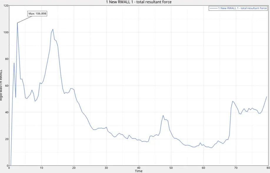
At the start of impact when the bumper comes in to contact with the Rigid wall the forces acting rapidly increased and comes down and when the Rails comes into contact with the rigid body again the forces increased later on rapidly comes down as the translational forces comes down.
Max Force on the Car BIW from the crash impact is 106.89 KN
FORCE DISTRIBUTION
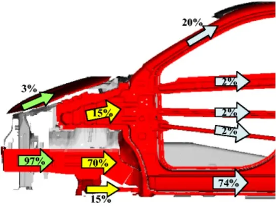 Reference of Energy Transfer
After the Impact the max force will be distributed close to above values through the Rails, Shotgun and A-pillar
These forces are captured by creating sections at different locations on a component as above i had created sections on rails, Shotgun and A-Pillar.
SECTIONAL FORCES
Sectional Forces in Longitudinal Rails
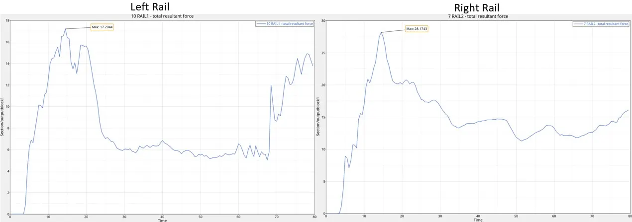
Maximum force transferred from the impact to the Left Rail is 17.2044 KN
Maximum force transferred from the impact to the Right Rail is 28.1743 KN
The total force transferred in the rails after the impact is the sum of forces transferred in Left and Right Rails is 45.3787 KN
From the calculation it is observed 43% of force is distributed through Left and Right Rails
Sectional Forces in Shotgun
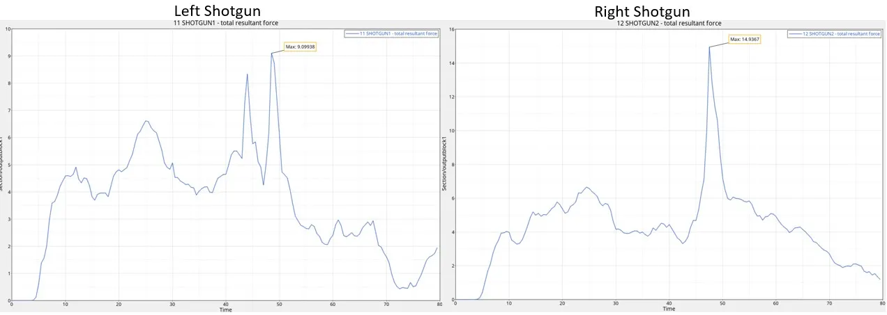
Maximum force transferred from the impact to the Left Shotgun 9.099 KN
Maximum force transferred from the impact to the Right Shotgun is 14.9367 KN
The total force transferred in the Shotgun after the impact is the sum of forces transferred in Left and Right Shotguns is 45.3787 KN
From the calculation it is observed 23% of force is distributed through Left and Right Shotguns
Sectional Forces in A-Pillar
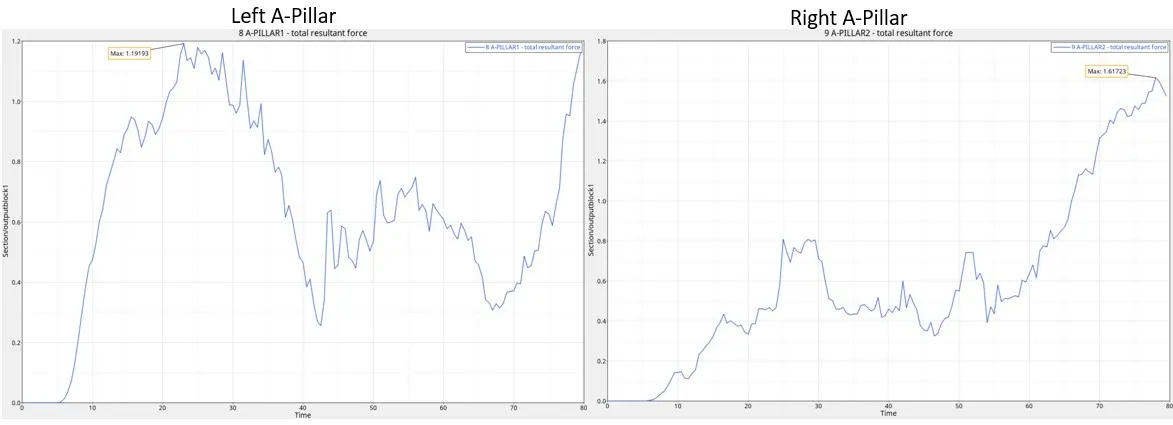
Maximum force transferred from the impact to the Left A-Pillar is 1.1919 KN
Maximum force transferred from the impact to the Right A-Pillar is 1.617 KN
The total force transferred in the Shotgun after the impact is the sum of forces transferred in Left and Right A-Pillar 2.82 KN
From the calculation it is observed 3% of force is distributed through Left and Right A-Pillar.
Similarly the forces will transfer from other BIW parts to the Rare of the Vehicle as we observe most of the energy will be transferred through lower part of the body which will less transfer of energy and forces on the upper side of the car body to reduce the effect on the occupant. BIW plays a pivot role in occupant safety.
Accelerometers
Accelerometers are installed on side rails to capture the rate of Acceleration and Deceleration of the vehicle when the impact happened. This helps to understand how quickly the vehicle slows down which will help the crash impact on the vehicle.
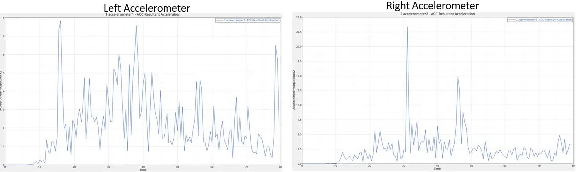
Once the Car hits the Rigid the acceleration plot shows that there is no sudden drop in the acceleration which is good result if the acceleration drops suddenly meaning all the forces are absorbed suddenly by occupant or very few components.
Intrusion
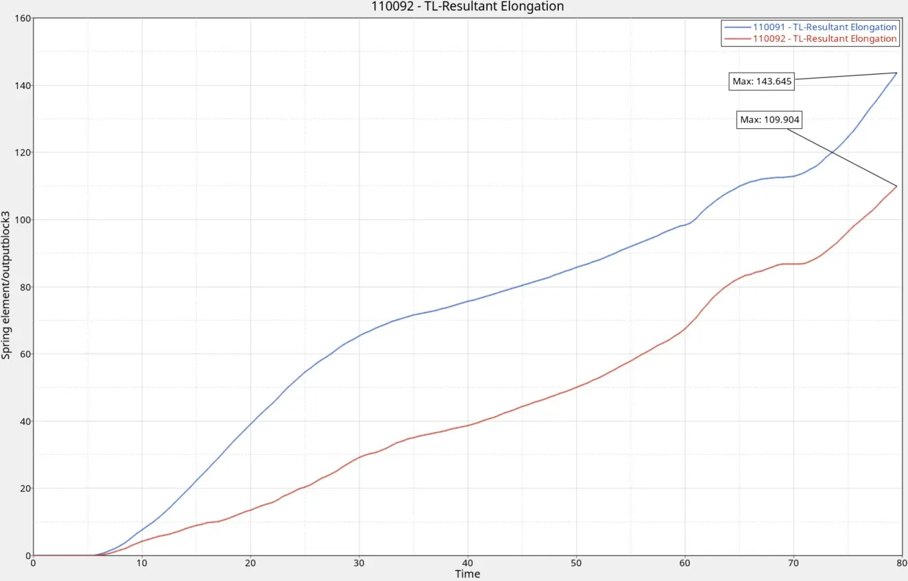
Max elongation is observed is 143.64 mm for the node 66695.
Displacement
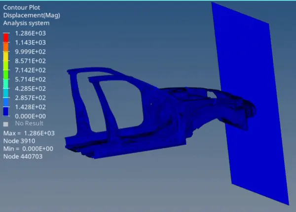
maximum displacement observed is 1.286e+3 mm
Conclusion
The given model is simulated for frontal crash using RADIOSS and results obtained are validated from the study.
Learning Outcomes
Learnt about Physics behind Crash Simulation and method to setup Frontal Crash simulation and in the setup many steps involved in which we need to create interfaces, Boundary conditions, Loading Conditions. And learn about how to request for outputs.
Learnt to Debug the results from the simulation and postprocessing of result.