Assignment 6-Frontal Crash Simulation Challenge
Project 1 - Frontal Crash Simulation Challenge
Objective:
Frontal crash-BIW
- Check unit system and either follow [Mg mm s] or [Kg mm ms].
- Create an appropriate interface, friction 0.2, and recommended parameters.
- Make sure of no penetrations and intersections.
- Correct rigid bodies if any issues.
- Create a rigid wall with friction 0.1.
- Compare the model weight with the full-scale 300k nodes model and use added masses to reach the target weight of 700kg while getting CG about the required range.
- Initial velocity 35 mph.
- Use a model checker to ensure good quality.
- Time-step :0.5 to 0.1 microseconds.
- Run 80 ms.
Output requests:
- Sectional force in the rails at the location of indicated node 174247.
- The axial force received on the rails from the bumper.
- Shotgun cross-sectional forces.
- A pillar cross-section.
- Acceleration curve received on the accelerometer at base of B pillar (on B pillar rocker).
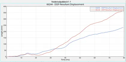
- Intrusions on the dash wall 66695,66244.
Note:
- Submit your simulation files including time and h3d files.
- Plot energies and notice any difference.
- Explain your errors and how to rectify them?
Procedure:
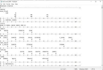
- Check the unit system of the given starter file (neon_front_0000.rad) by opening it in Notepad/Notepad ++.
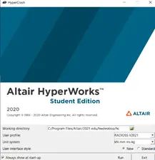
Open Hypercrash, (from applications tab of Hypermesh) and set the unit system: kN mm ms kg.
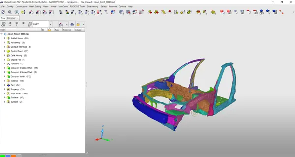
Now drag and drop the starter file (neon_front_0000.rad) in the Hypercrash.
- To check penetrations and Intersections, Quality -> Check All Solver Contact Interfaces -> Select all parts -> Check penetration.

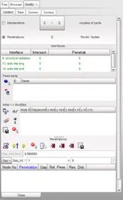
There are no penetrations or intersections in the model.
3. Compare the model weight with the full-scale 300k nodes model and use added masses to reach the target weight of 700kg while getting CG about the required range.
We have to add mass to the current model which will be equal to 700 kg and CG in the required range.
To Check the mass and CG of the current model,
Mass -> Balancing
The pink mark shows the current CG of the model (click specs like icon)
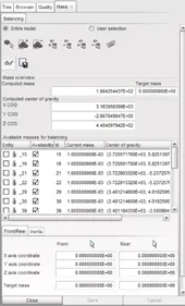
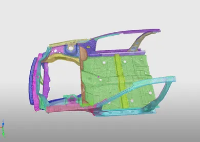
The total mass to be added to get 700 kg is 511.575 kg

Mass can be added for both front seats (Driver & Passenger) of 85 kg each and 341.5 kg for the Rear Seats and Fuel tank.
To Add required mass, Load case -> Added Mass
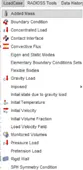
Create New -> Type 1 (Mass distributed to each node of node group) -> Added mass (85kg each and 341.5kg) & select the required nodes where the mass to be added (Passenger-Driver seats & rear seats-fuel tank).
We have added 3 new masses of a total of 511.5 kg to the current model.
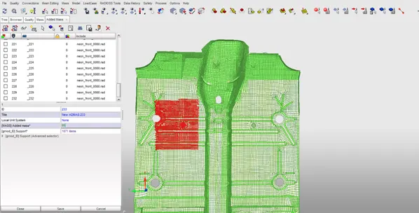
Now we have gained the CG in the required range and mass of 700 kg
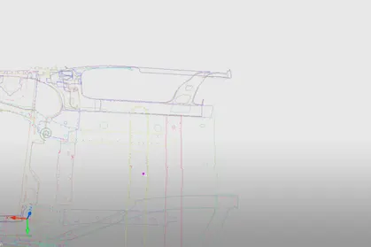
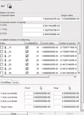
Export the model in rad file File-> Export -> RADIOSS & Import it in Hypermesh.

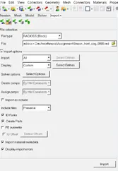
- Create an appropriate interface, friction 0.2, and recommended parameters.
Delete all the groups to create the contact interface (Groups in model browser) for the current model.
Create a new interface namely for Self-Contact & Bumper headlights with recommended properties.
In Model Browser,
Create -> Contact
Type 7
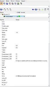
Istf = 4, Igap = 2, Idel = 2, Stmin = 1, Gapmin >= 0.5, Inacti = 6, Iform = 2.
For Self-Contact – select all components for Master & Slave selection
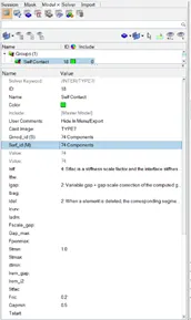
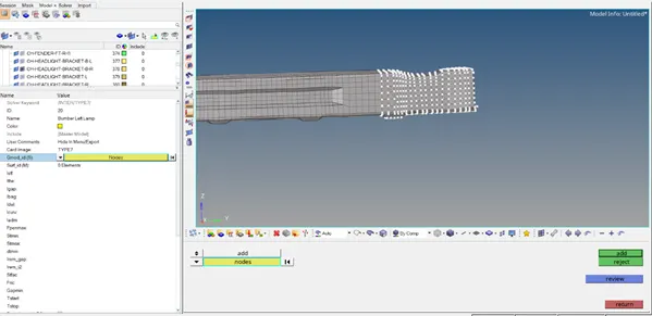
For Bumper-Head light contact Interface – Nodes from the bumper component as Slave & Head Light component as Master
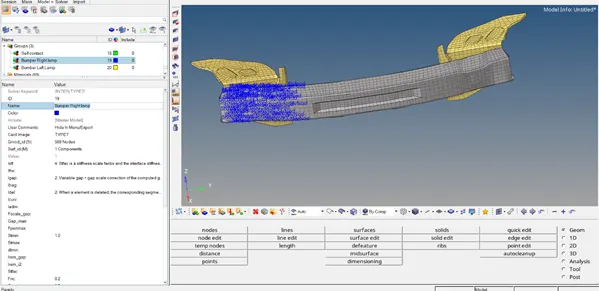
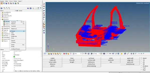
After creating the contact interface, review to check whether the Master and Salves are selected properly.
Red – Slave, Blue – Master
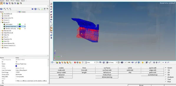
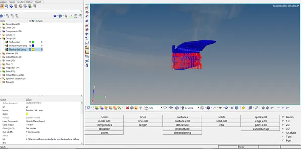
- Create a rigid wall with friction 0.1
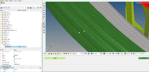
In Solver browser, Create -> RWALL -> PLANE
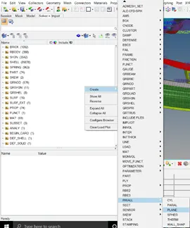
For creating a rigid wall, we need a reference node – for that temp node is selected on the model, and using translate duplicating the temp node we can get the reference node.
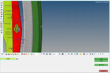
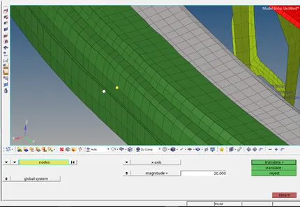
Now select that reference node for XM, YM, ZM as values for the rigid wall
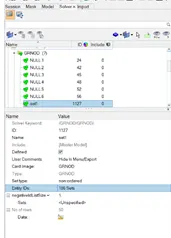
For grnod_ID1 – Create a set for selecting all the nodes of the model
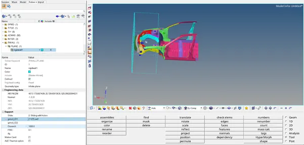
Normal = -1,0,0 as the normal of the rigid plane is to be in the negative x-axis for the model.
Slide = 2, Dsearch = 1000 & Fric = 0.1 (given)
- Initial velocity 35 mph.
Create -> Boundary Conditions -> INIVEL
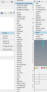
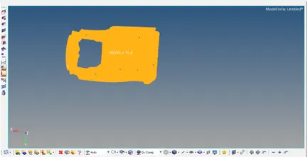
Give Velocity component: 15.6464 kmph and select all the sets in the grnd_ID.
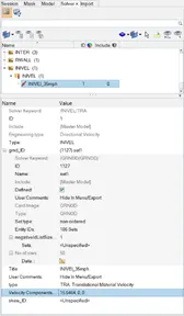
Using Review check whether all the sets are assigned with the given Initial Velocity.
For Output Requests
- Sectional force in the rails at the location of indicated node 174247.
The axial force received on the rails from the bumper.
Shotgun cross-sectional forces.
A pillar cross-section.
We have to create Sectional Forces on the Rails, Finder, and Bumper.
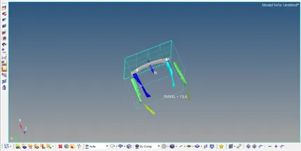
Before creating Sectional Forces, we have to create moving frames on the components.
Create -> Frame -> MOV -> create by node reference -> z axis -> yz plane,
This system will be selected in the frame_ID while creating sections.
Create -> SECT -> SECT
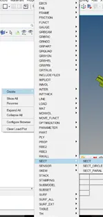
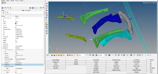
Select the frame nodes on the component for the N1, N2, N3 then deltaT = 0.1, alpha = 0.67 & Ifame = 12.
For grshell_id, Create a set and select the elements around the frame created of the component.
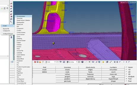
- Acceleration curve received on the accelerometer at base of B pillar (on B pillar rocker).
Create -> Accelerometer (Model Browser)
Select the node on which accelerometer to be created – both sides
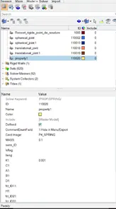
- Intrusions on the dash wall 66695,66244.
Create Spring from the given node to the opposite component Crossbeam.
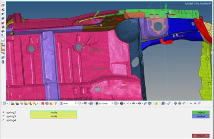
Assign spring properties, select card image = P4_spring with mass = 0.1 and stiffness k = 0.001
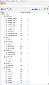
- Creating TH for all the output requests.
In Solver browser,
TH – SECT – Self Impact, Bumper Right & Left Light
RWALL – Rigid Wall
Section – Rail, Fender, Bumper
Spring & Node – Intrusion for nodes
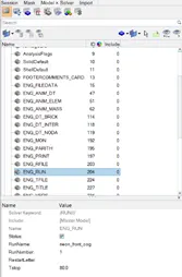
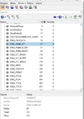
- In ENG_RUN set Tstop = 80 & ENG_ANIM_DT set Tfreq = 5.0
Check for the model error in both Hypermesh & Hypercrash
If there is any error, try to sort it out by auto-resolve
Hypermesh -> Tools -> Model Checker -> Radioss
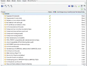
Hypercrash -> Quality -> Model Checker -> Run
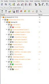
In the Analysis panel, select Radioss and save the input file as neon_front_cog_run_0000.rad in a separate folder (to save the animation files), mentioning the option = “-nt 4”.
Then run the input file, by selecting Radioss to perform the simulation.
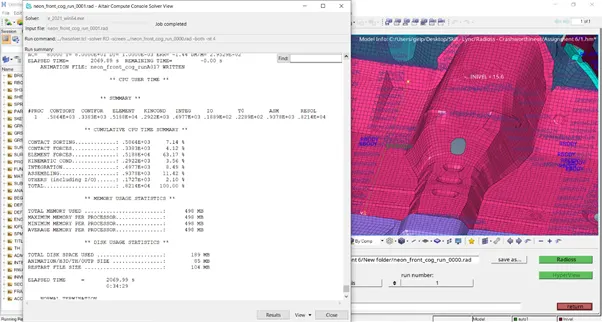
ELAPSED TIME = 2069.99 s
0:34:29
Energy Error = -1.4%
Mass Error = 0.2953E-01
Select Results, to view the simulation – Select the Contour for displacement, von mises, contact forces and save the files.
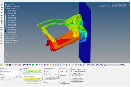
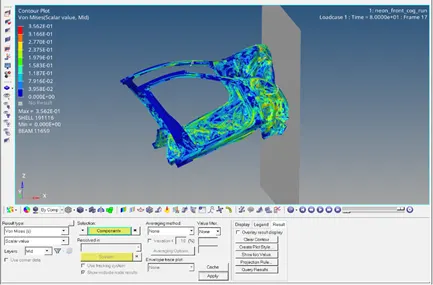
Go to Hypergraph, 2D to plot the desired graph for comparison.
Energy Curves:
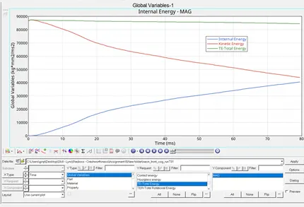
Max Energy
- Internal Energy (79.5,40492)
- Kinetic Energy (0.5,87311)
- Total Energy (1.0,87371)
Contact Energy:
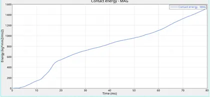
After the car hits the rigid wall, contact energy increases and reaches the maximum.
Rigid Wall
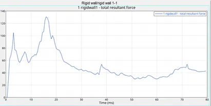
The rigid wall has a max of 130.6 kN at 16 ms, Also the first peak is due to the first contact of the car on the rigid wall which can be confirmed from the contact energy graph.
Output Requests
Sectional Forces
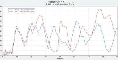
Max cross sectional force - Left 4.7 kN/mm at 67.5 ms
- Right 3.46 kN/mm at 51.5 ms
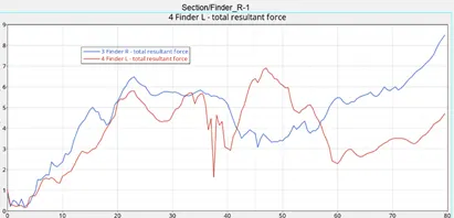
Max cross sectional force - Left 6.9 kN/mm at 47 ms
- Right 8.5 kN/mm at 79.5 ms
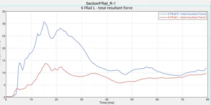
Max cross sectional force - Left 13.7 kN/mm at 16 ms
- Right 30.75 kN/mm at 15 ms
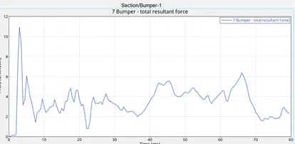
Max cross-sectional force for the bumper is 10.9 kN/mm at 3 ms, which would be the same time at which contact energy starts increasing and the rigid wall force reaches its first peak.
Accelerometer
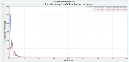
Max Acceleration at Left rocker is 502.57 mm/ms2 at 0.5ms
at Right rocker is 194.4 mm/ms2 at 1.5ms
Interface:
Self–Impact:
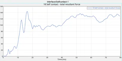
Self-impact forces reach 144 kN at 16.5 ms.
Bumper – Head Light Impact interface
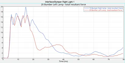
Left reaches max 16.72 kN at 16 ms
Right reaches max 19.8 kN at 15 ms
After a certain time since there is no impact as per the animation forces decrease.
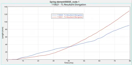
Intrusion – Spring Displacement at 66695,66244 nodes
Results:
Thus, the given front half model was made to do the crash simulation with the required given input set up along with the output parameters calculated.
Learning Outcome:
Setting up for car frontal crash
Adding masses to alter CG at the required place
Adding Boundary Conditions
Setting up the interface with recommended properties
Setting up Sectional forces for the calculation
Debugging errors
Providing results with output blocks
Google Drive Link for T01 file