Assignment 6-Frontal Crash Simulation Challenge
Objective:
To perform crash analysis on Front end of the car and report obervations based on the output received.
Case setup:
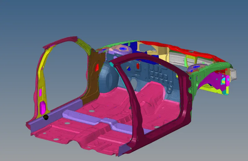
A vehicle structure with 10k elements is given for doing front crash analysis with given parameters. The vehicle structure have all the parts essential for front crash such as cross member, shot gun, rail, A pillar etc. other parts are deleted so as to run the simulation in Hypermesh student edition. In this model recommended boundary conditions are applied and simulation must be run to get the requested output. The comments must be made on the obtained observations.
Unit system check:
The unit system used is Kg mm ms

Inteface creation.
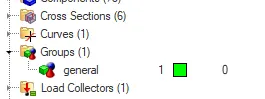
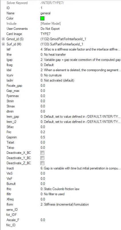
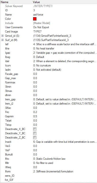
The unnecessary interface is removed and a single interface (TYPE 7) is created with necessary parameters.
Rigid Wall
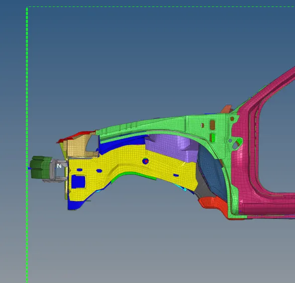
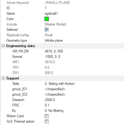
A rigid wall is created with friction 0.1 in front of the cross member.
Mass correction and CG
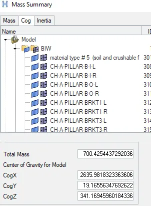
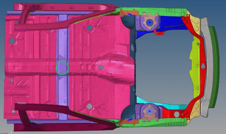
The mass of the vehicle is increased to reach 700kg and Centre of gravity is ensured to be near driver.
Initial velocity
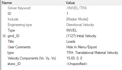
Initial velocity of 35 mph or 15.6mm/ms is applied to all the nodes.
Time step and Engine card
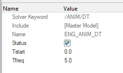
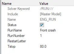
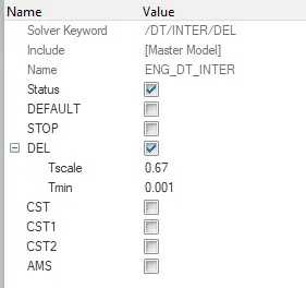
Time-step is kept for 1 microsecond.Simulation is run for 80 ms.Animation frame frequency is set to 5ms.
Output requests
Section
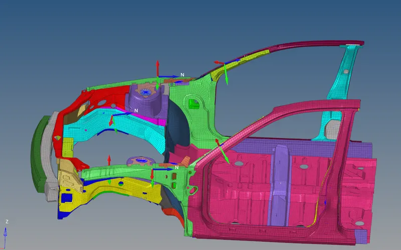
Section is created at rails, shotgun and A pillar to measure the force as shown below with recommended parameters.
Axial load
Interface is created between crossmember and rails with recommended parameters.This can be used to measure to measure the axial load transfered.
Accelerometre
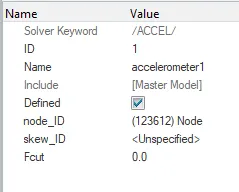
Accelerometre is created below the B pillar to measure the decelaration magnitude.
Penetration.
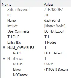
Penetration is measured at dash panel with respect to a mobile frame (system) created on floor to measure penetration of impact in driver compartment.
Check points
The model is checked for penetrations by selecting Tools --> penetration. No penetrations are found
Then also model is checked for errors and warnings by selecting
Quality--> Model checker --> Run in Hypercrash.
There where no errors and warnings where acceptable.
Output graph and Observation.
The model is run by Analysis--> Radioss. Then the output generated is analysed.
Output check
The output file have energy error less than 15%. So, the output is acceptable.

Sections at Rail, Apillar and shotgun
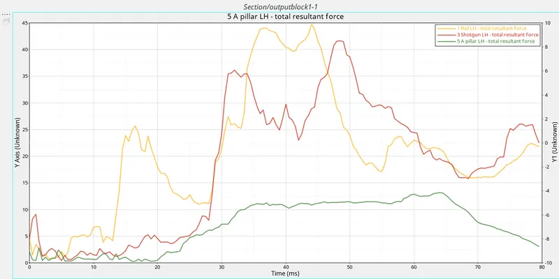
The output graph for force received on each part against time is plotted below.
Observation:
From the graph above it can be seen that the maximum force of 45kg/mm2 is received at Rail at approximately 40ms. Shotgun also receives similar force. Apillar receives very less force (15kg/mm2) comparitively since the force is distributed to other parts in the lower region of the vehicle.
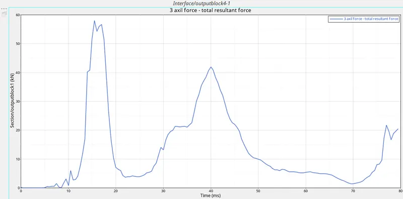
Axial load through crossbeam.
The total force passing through crossmember-rail interface is plotted below against time.
Accelerometre near B pillar.
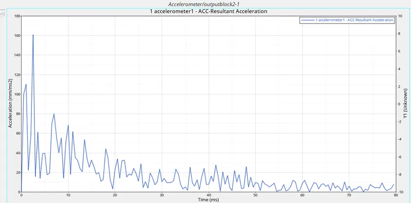
The decelaration of the vehicle is measured at node near B pillar and plotted below.
Observation:
From the graph it can be seen that the decelaration is at max peak (160mm/ms2) at around 3ms which is when the crossmember comes in contact with rigid wall. The occupant may be injured at this point. This can be avoided by further improving the design of crossmember to absorber energy more efficiently.
Penetration
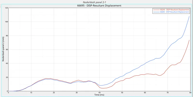
The penetration of dash wall in the driver compartment is measured and plotted below.
Observation:
At intial stage of the impact there is no intrusion in the driver compartment but at 80ms the dash wall is deformed towards driver compartment for 100mm.
Total Energy:
Internal energy, Kinetic energy, total energy, hourglass energy and contact energy is plotted against time as shown below.
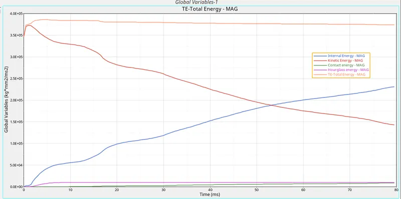
The contact energy and hourglass energy is very less which is consistent with the minimum energy error of simulation. Th kinetic energy is max at 0ms and is reduced during crash. Internal is min at 0ms and is increased during crash which simulates the energy being desipated by cross member.
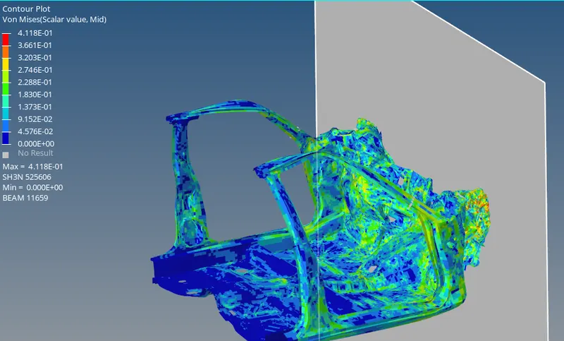
Von Mises stress:
From the below image we can see that the max Von mises stress is 0.4Kg/mm2.
Conclusion:
- The reaction force from the rigid wall during collision is absorbed by deformation of vehicle structure.
- The max deceleration of the vehicle is peak at he intial few ms and is decrease gradually towards end, this can be further made uniform by improving the vehicle structure design or simulation improvement by running full model.
- The force distribution through different structure of vehicle is observed. most of the force pass though shot-gun and rail.
- Hence, the simulation of Vehicle Front crash is studied and observations are reported.