Assignment 6-Frontal Crash Simulation Challenge
Aim: To simulate Frontal crash analysis of the Neon Deoge Model Car, for the Front end cut-section and perform to be Hit on the Rigid Walls.
Objective:
- Check the unit system and follow[Mg mm s] or [Kg mm ms].
- Create an appropriate interface, friction 0.2, and recommended parameters.
- Make sure of no penetrations and intersections.
- Correct rigid bodies if there are any issues.
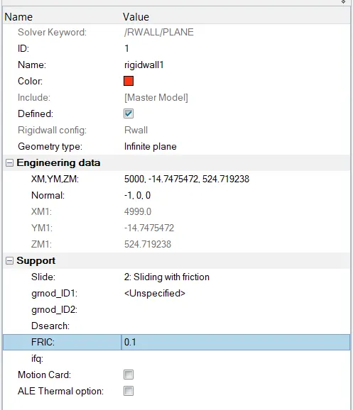
- Create a rigid wall with a friction of 0.1.
- Compare the model weight with the full-scale 300k nodes model and use added masses to reach a target weight of 700kg while getting CG about the required range.
- Initial velocity 35 mph.
- Use a model checker to ensure good quality.
- Time-step:0.5 to 0.1 microseconds.
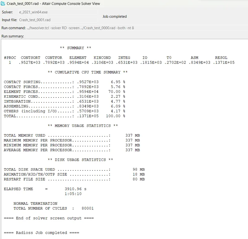
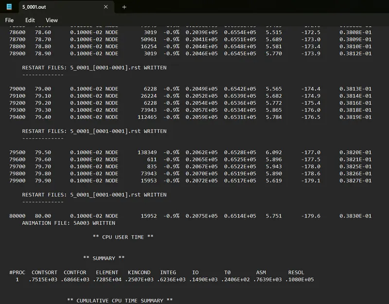
- Run 80 ms.
Outcomes:
Results:
- Sectional force in the rails at the location of indicated node 174247.
- The axial force received on the rails from the bumper.
- Shotgun cross-sectional forces.
- A pillar cross-section.
- Acceleration curve received on the accelerometer at base of B pillar (on B pillar rocker).
- Intrusions on the dash wall 66695,66244.
Procedure:
We will be using Hypercrash and Hypermesh to set up the model. Some checks will be done in Hypercrash and some in Hypermesh. First, we will import the model into Hypercrash and check for Penetration and make sure the units are in Kg mm ms.
Starter File:
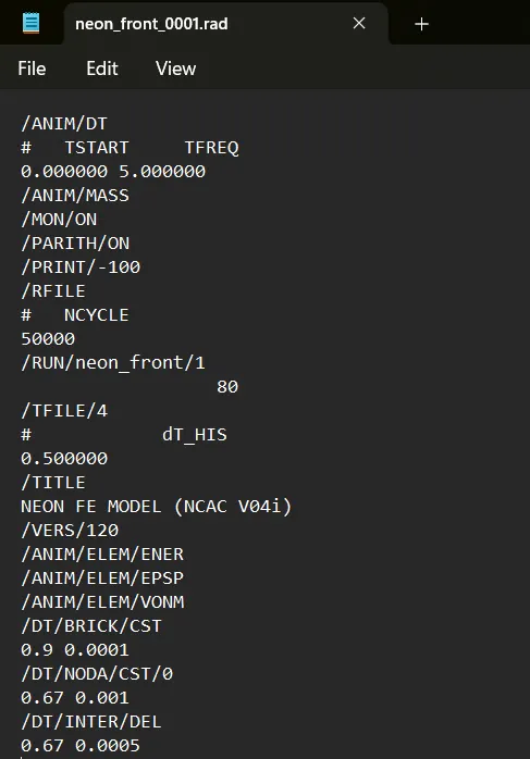
Time-step is set to 0.5ms, NODA is used when an element fails for the required timestep then DT/NODA will act as add-on mass for those nodes.
Checking for the units used for this model:
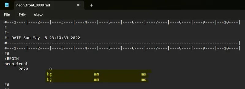
The unit check can be done without opening the model. We can just open the Neon_front_0000.rad in a notepad where we will be able to check the units.
Version Information:
The next step is to set the Unit conversion in the Hypermesh:
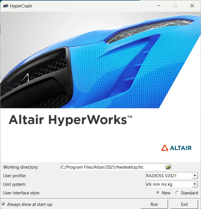
"Select Application -> Choose Hypercrash (Radioss User Interface) -> Unit System -> KN,mm,ms,Kg -> Run"
Now we have run the Hypercrash for Checking Penetration and Intersection checks in the model.
Important of penetration and Intersection:
Penetration is defined as the overlap of the material thickness of shell elements.
The intersection is defined as elements that pass completely through one another.
All models and especially impact models should be checked for penetrations and intersections to make sure there is no penetration and intersection. If either one case possibly occurs we could face a worse case of the results, due to the penetration of interfaces that we create.
To check the Penetration,
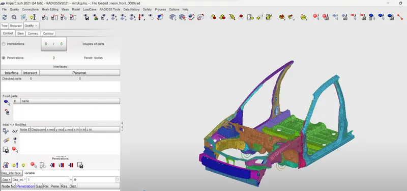
Go to Hypercrash -> Click Quality -> Check Intersection on tree -> Select parts -> Click on Check penetration
Below it shows, there are no intersections and Penetrations.
COG and Additional Of Mass Element:
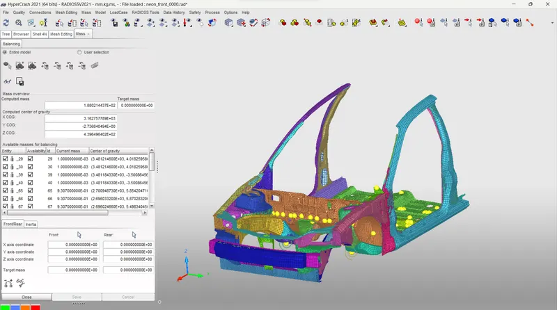
As per the requirement, we need to have 700Kg or 0.7Ton weight should be there in the car.
The below picture shows the default mass of the structure which of 1.88kg, here we going to add mass at the Bottom frame of the car structure.
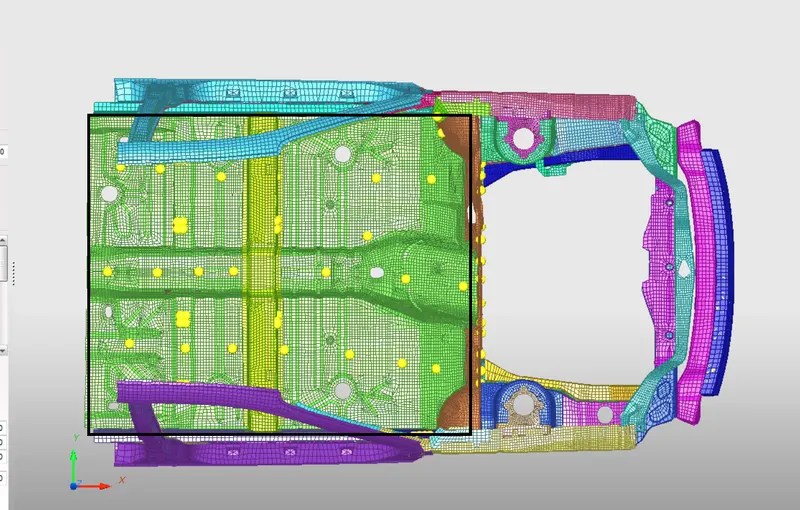
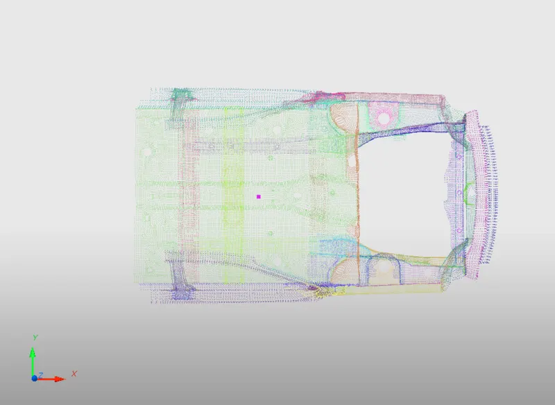
Top View:
From this view, we can able to see the bottom part of the car, in the highlighted part
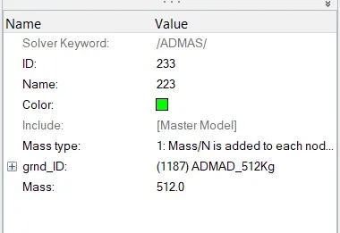
After the addition of Mass:
Now the mass is changed into 700 kg or 0.7 Tons.
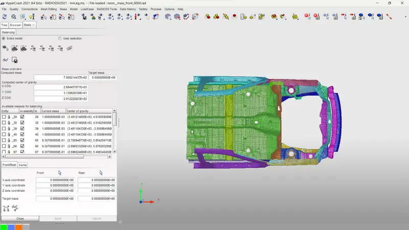
CG is been shifted to center of the structure as highlighted.
Applying initial velocity:
solver > create > boundary conditions >INIVEL
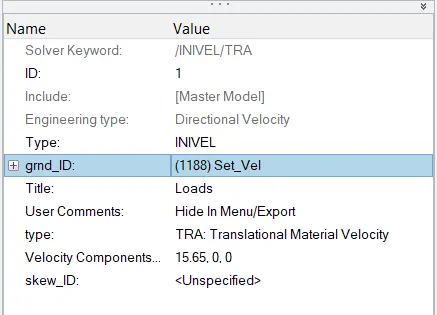
the velocity need to be applied is 35Mph,
since the units are kg mm ms, therefore the value to input is 15.65mm/ms
Then we have to create a Type 7 contact interface between the All components which is presented here as 72Components.

Friction is set to 0.2 for all the components.
Next, we have to create Rigid walls for impacting the car body for crash analysis.
Rigid Walls:
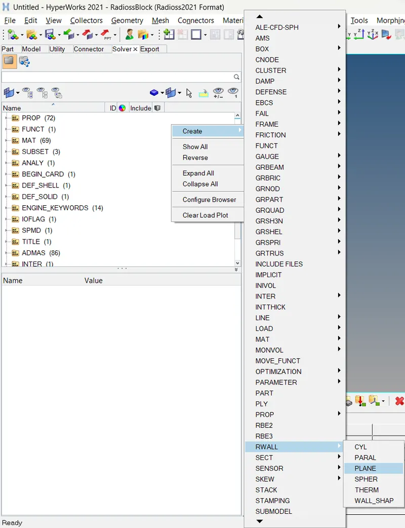
Rigid walls are been created at the 5000 coordinates of the RWall plane.
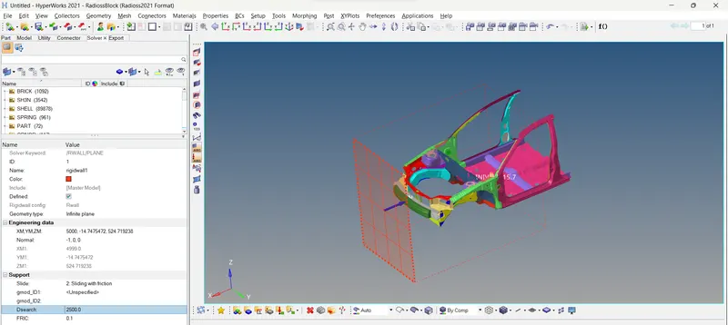
Inputs are shown below:
CREATING SECTIONS:
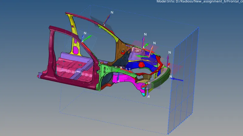
We will be Creating Sections at A-Pillar, Shot Gun, rails, and Bumper in order to Study the sectional forces. We have to know how the forces are transmitted from the Bumper to the Dashboard and the rate of deformation. It is done in order to ensure the safety of the passenger.
Certain components have to deform more than the others so that the forces are distributed correctly leaving very little force left to transmit inside the cabin.
To go to this option Solver -> Create -> Frame -> MOV -> Select the nodes as shown below
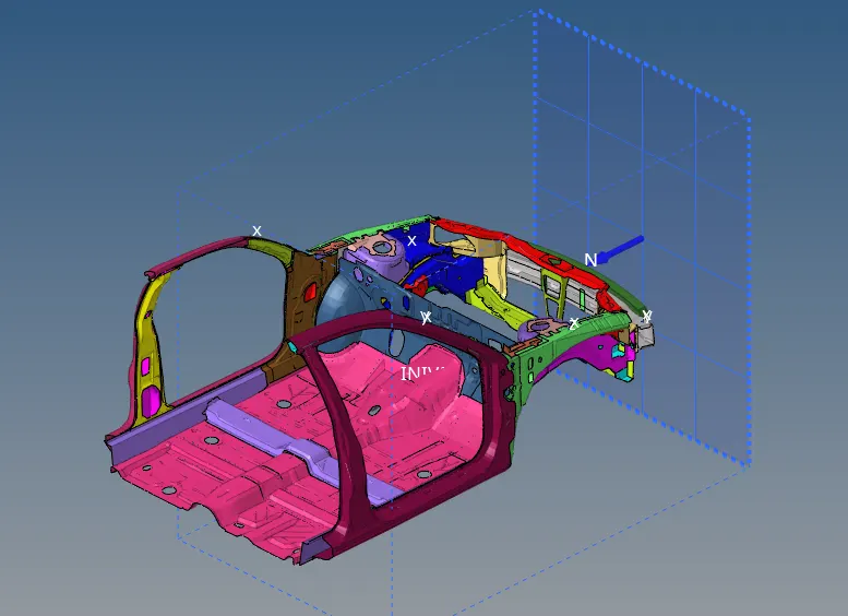
After Creating the Section:
Define the Nodes with reference to the Axis of the Frame.
• Enter the values of Delta T as 0.1
• Define the cutting plane by a group of elements and its orientation by a group of nodes (grshell_ID)
• Hence, the sections will be created.
CREATE ACCELERATION NODES:
Creating Accelerometer at both sides of the B pillar.
An accelerometer is a basic technology that converts mechanical motion into an electrical signal. It is an electromechanical device that measures acceleration forces, whether caused by gravity or motion.
To create accelerometer
Go to Model browser >> Create >> Accelerometer >> Select Node_ID >> Select node >> Proceed
This is done to get the Acceleration output of the Crash i.e., the rate of deformation.
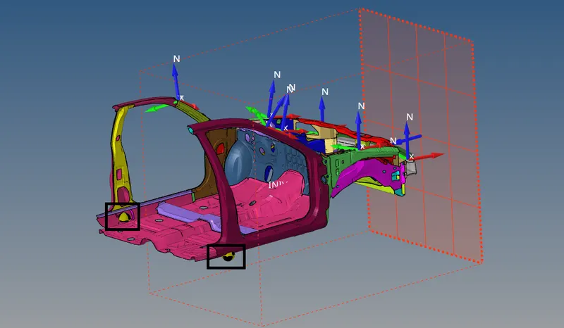
Highlighted are for Acceleration nodes.
CREATING SPRINGS:
We are planting spring elements to study the intrusions (forces inside the cabin causing deformation/rupture). Create 2 parallel spring elements from the indicated nodes (66339, 66220) to the Crossbeam.
Springs can be created from the 1D Panel > Springs
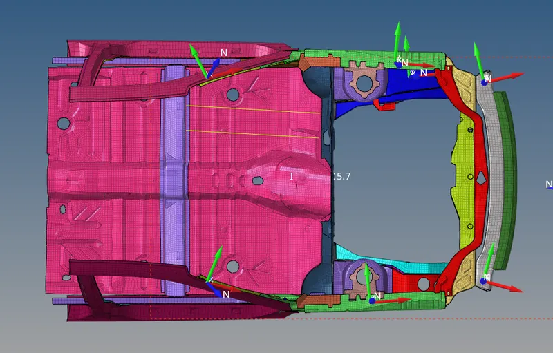
We have to provide the springs with their respective properties.
Go to model Browser >> Create >> Property >> Rename as Springs
After creating a property, a new tab will open there we have to select CARD image as P4 SPRING and Mass as 0.001, and Stiffness as 0.001 and assign all these properties to the spring.
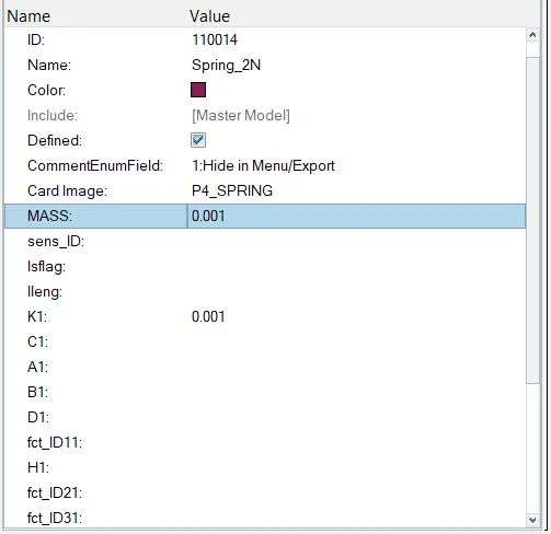
Make sure to create a Time History file for these Springs Individually so that we can view the intrusions.
CHECKS:
These checks can be done via both Hypermesh and Hypercrash but it is recommended to check via the Hypercrash module. Before exporting the model we will be checking for Unused and Empty. Also, make sure all the parts are connected, or once the simulation is done the results will be wrong with parts flying.
Tools>>Unused and Tools>>Empty and delete the unwanted data in the model and export them.
The Model checker will give us any warnings and Errors regarding the model definition and, the boundary and Kinematic conditions, etc.
For example:
- Boundary Condition is not defined properly
- Incompatible Kinematic Condition
- The Part Property or material is not defined properly, etc.
- We can avoid the Warnings as the solver will take care of them.
But we must fix every Error in order to get a successful simulation free of problems
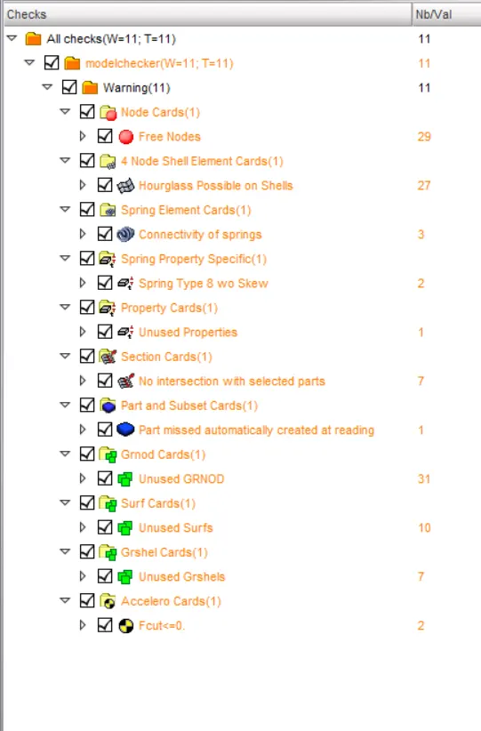
Results:
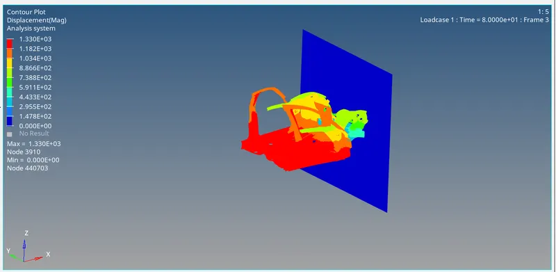
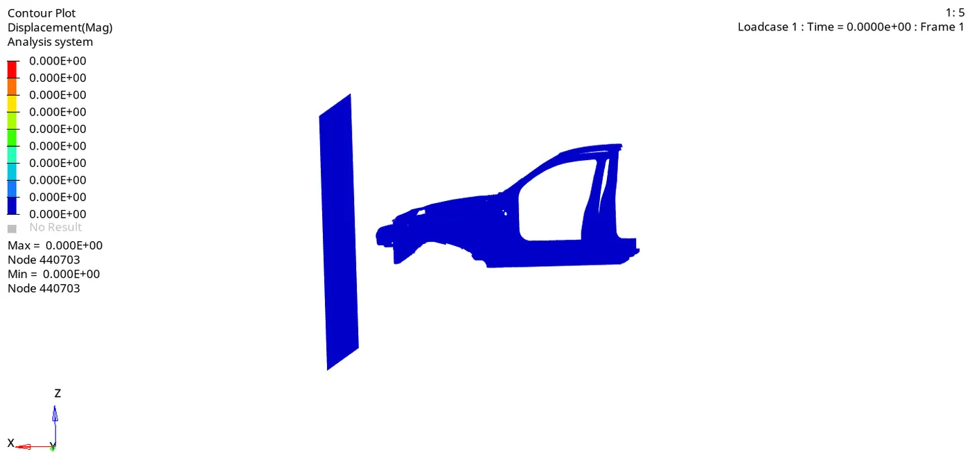
Displacement:
Max displacement of 1.33e+3 Mpa and Min Displacement of 0 Mpa
Von-Mises Stress:
Max stress of 2.76e-1 N/mm^2 and Min of 0 N/mm^2
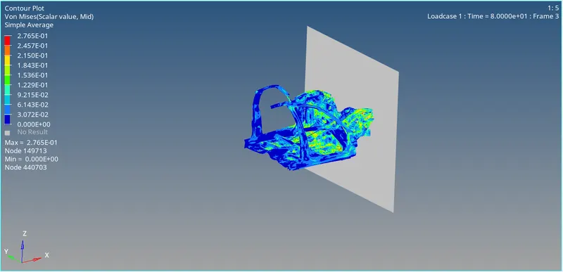
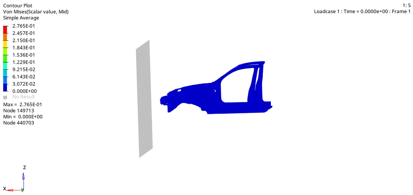
Rigid Walls:
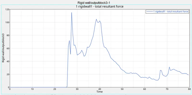
Acceleration curve received on the accelerometer at the base of B pillar:
Right acceleration plot from the rear view of the car:
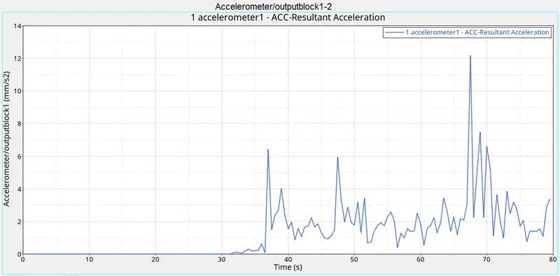
On the right base of the B pillar, the maximum resultant acceleration experienced is 12.12mm/s2.
Left acceleration plot from the rear view of the car:
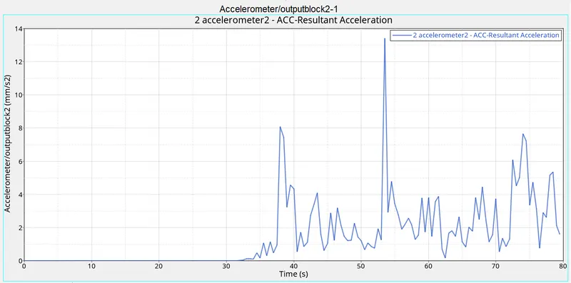
On the right base of the B pillar, the maximum resultant acceleration experienced is 13.87 mm/s^2
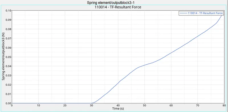
Intrusions on the dash wall 66695,66244:
The total intrusion at node 66695:
The total intrusion at node 66695 is 129.2mm [all units are in sec been converted to ms].
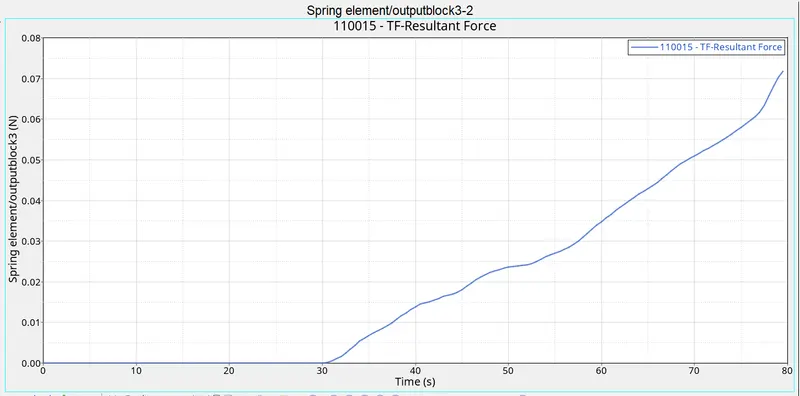
The total intrusion at node 66244:
The total intrusion at node 66244 is 86.33mm. [all units are in sec been converted to ms].
Conclusion:
The given model was simulated for the frontal crash using Radios and the results obtained were validated. The hourglass energy is less than the internal energy. The graphical results were plotted for all the test cases. From the simulation, it can be observed that there was minimum deformation in the cabin, and also minimum intrusion was found in the driver's seat area.