Assignment 6-Frontal Crash Simulation Challenge
Aim: To perform a frontal crash of a car at 35mph in radioss. using the following boundary conditions:
Objective:
Boundary Conditions:
- Check unit system and either follow [Mg mm s] or [Kg mm ms].
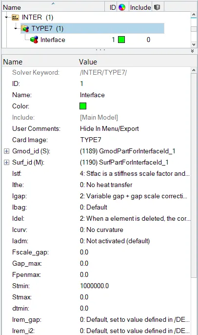
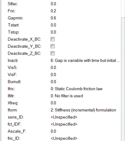
- Create appropriate interface, friction 0.2 and recommended parameters.
- Make sure of no penetrations and intersection.
- Correct rigid bodies if any issues.
- Create rigid wall with friction 0.1.
- Compare the model weight with the full scale 300k nodes model and use added masses to reach target weight 700kg while getting CG about the required range.
- Initial velocity 35 mph.
- Use model checker to ensure good quality.
- Time-step :0.5 to 0.1 microseconds.
- Run for 80 ms.
To plot
- Sectional forces in the rails at location of indicated node 174247.
- Axial forces received on the rails from bumper.
- Shotgun cross sectional forces.
- A pillar cross section.
- Acceleration curve received on the accelerometer at base of B pillar (on B pillar rocker).
- Intrusions on the dash wall 66695,66244.
Introduction:
A frontal impact car collision, also known as a head-on collision, is one of the deadliest types of car accidents. A frontal crash is the most common crash resulting in a fatality. The severity of the injuries depends on the speed of the vehicle(s) and safety features of your car. These types of crashes often cause the following injuries. The vehicles are head-on into a solid barrier and the test conducts a frontal-offset crash into a deformable barrier that mimics another vehicle.
Procedure:
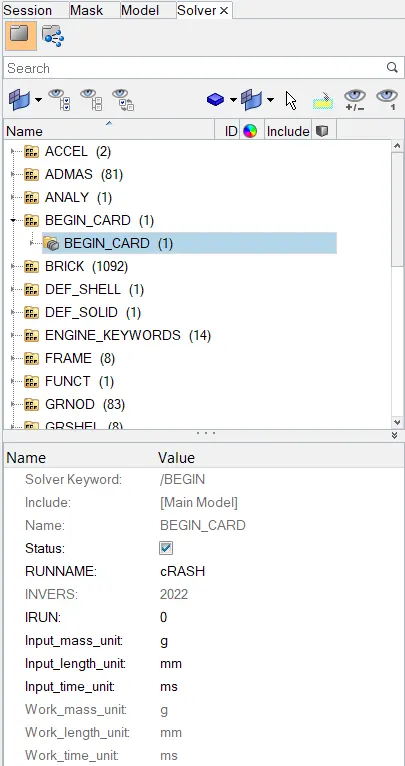
- Import the given .rad file into hypermesh and check for the begin card for the units in the solver browser.
- Create a type 7 interface with friction as 0.2 using the following conditions:
- To make sure there are no penetrations and intersection in the component by Tools > Penetration Check
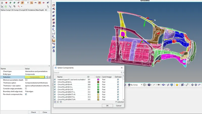

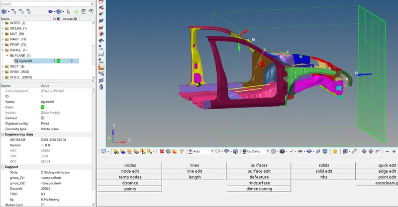
- To create a rigid wall with a friction of 0.1 by Create > Rwall > Plane > Following Conditions. Select a node at the front bumper and set the at xm, ym, zm by selecing a node and add a normal reaction to the wall as -1 for the reaction.
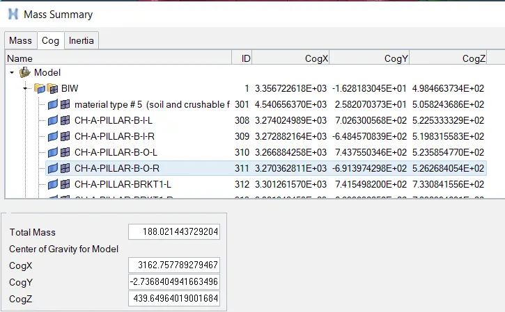
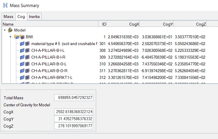
- To compare the model weight with the full scale 300k nodes model and use added masses to reach target weight 700kg while getting CG about the required range. The given model was less in mass with 188 kg. We check by using Tools > Mass Details > Mass, cog and inertia and check the mass.
We create a node using the above x, y and z coordinates and then create a admas(512kg) > using settings with the following set of nodes and let the cog point be at the center near the purple member/component where the springs are attached.
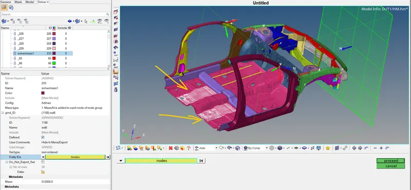
At last we get:
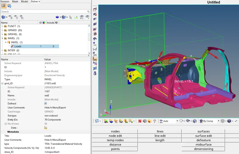
- To create a initial velocity of 35 mph for all the components. (35mph = 16.65mm/ms)
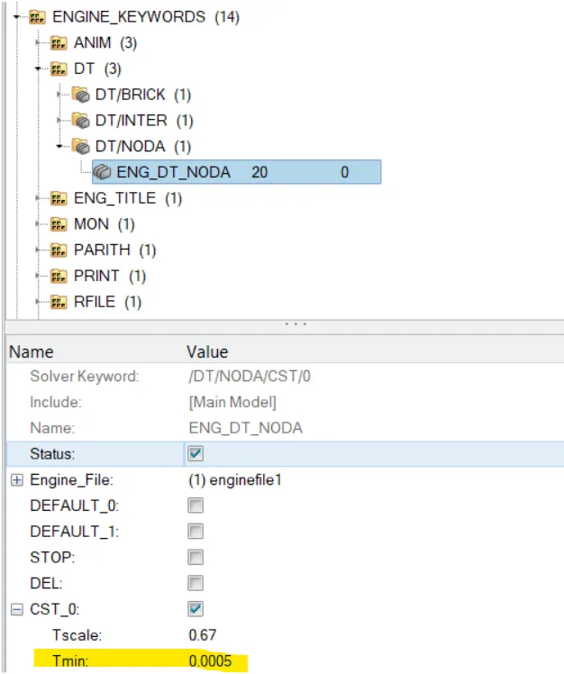
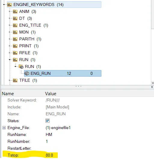
- We set a time step for 0.5 microsecond (0.0005ms) and run for 80 ms.
- Now lets create moving frames for recording forces in the section (Frames/Mov - Describes moving frames. Relative motion with respect to a reference frame).
We first hide all the components and work on the rail by pressing D > selecting frame > reverse. For sectional forces in the rails at location of indicated node 174247 we create a node at the given location and select 3 nodes by using the right hand thumb rule where the thumb points the direction in which the sectional force is to be calculated.

Following mov frame is created:
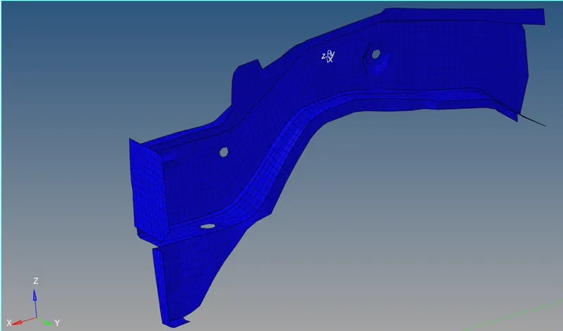
Similarily we create the mov frames at: opposite location of indicated node 174247; the rails from bumper; Shotgun cross sectional; A pillar cross section.
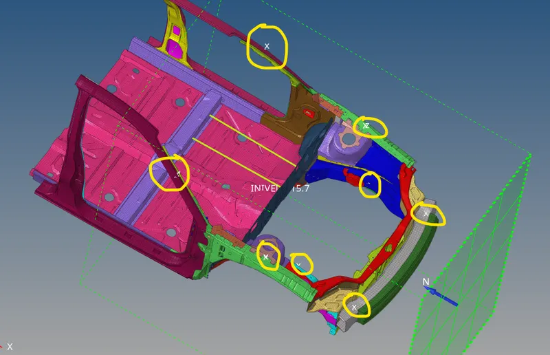
- For an acceleration curve received on the accelerometer at base of B pillar (on B pillar rocker); create an accelerometer at the given location by selecting the node with a cut off frequency of 0.66. Similarily we do it on the opposite side:
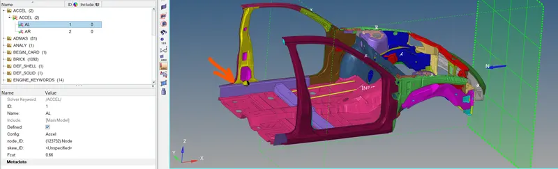
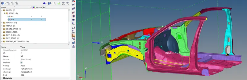
- For intrusions on the dash wall for the nodes 66695, 66244; we create 2d springs for the deflection.
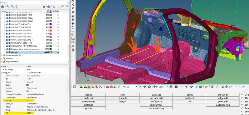
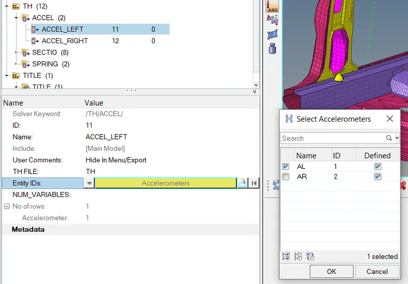
- Now, after creating all the bcs for required forces, we now create time history file for recording the forces by create > TH > accel and select the accelerometer created.
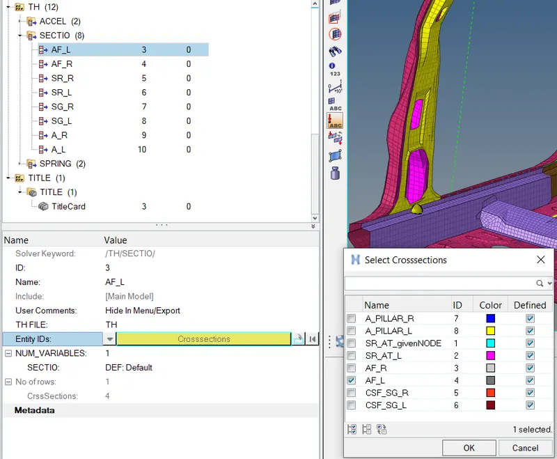
Similarily for sectional forces, we create TH > Sectio > select CrossSections created:
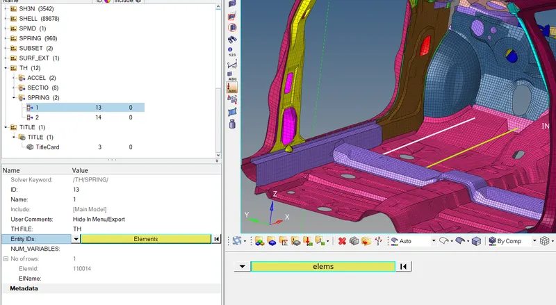
- Similarily for both springs by creating TH > Springs > SelectSpringElement.
- After creating all the TH files for all the outputs requested following is obtained:
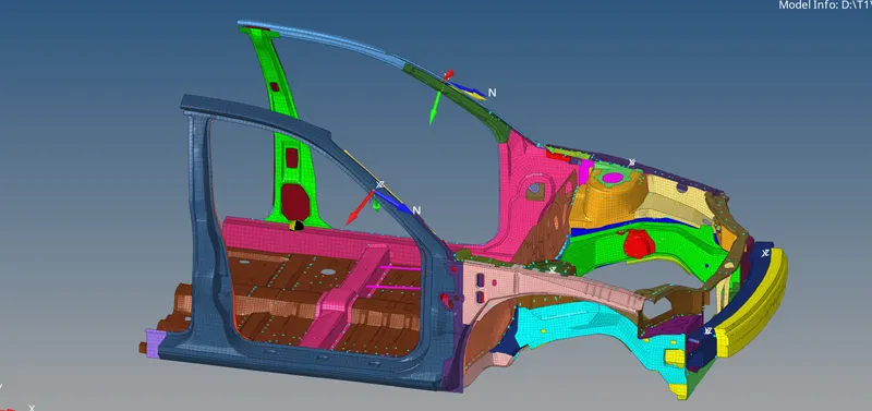
- At last we check for any errors by Tools > Model Checker > Radioss Block > Run and then run the simulation by analysis > radioss > radioss and obtain the following Results.
Results:
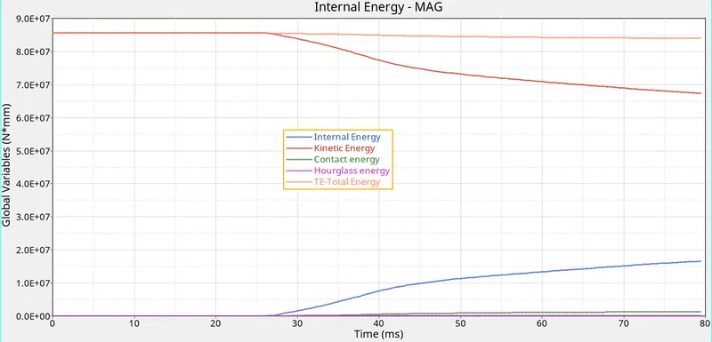
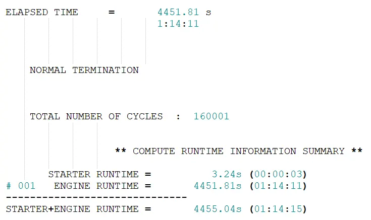
Elapsed time is 1hr 14mins with energy error as -1.7%, 0.1667e8 as internal energy, 0.6730e8 as total kinetic energy and 0.197e-3 as mass error.

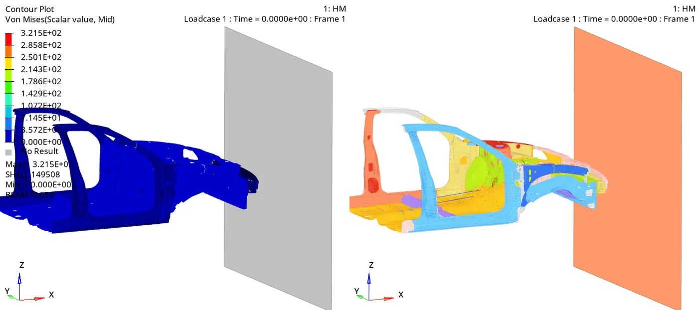
Max stress of 321Mpa is observed.
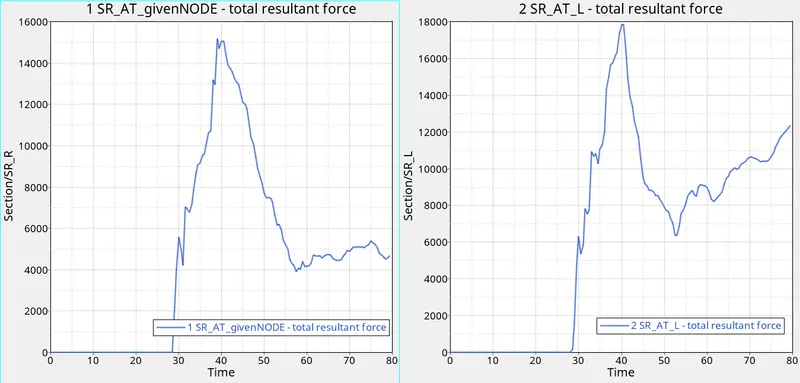
At 40ms, most of the cross sectional forces are observed to be higher.
Sectional forces in the rails at location of indicated node 174247 and at opposite side. Around 15200 N on the given node and 17900 N on the opposite side on the rail.
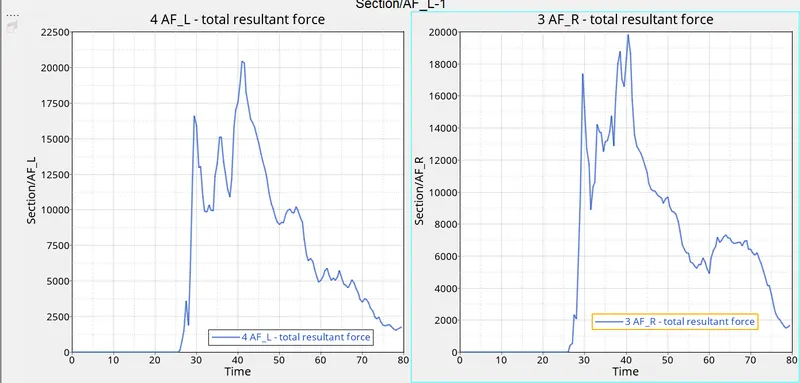
Axial forces received on the rails from bumper (AF_L - Axial Force Left Rail & AF_R - Axial Force Right Rail). Around 20625 N on AF_L and 20000 N on AF_R was observed.
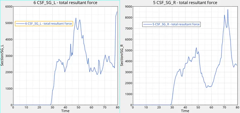
Shotgun cross sectional forces. ( CSF_SG_L - cross sectional force of shotgun at left and CSF_SG_R - cross sectional force of shotgun at right) Around 5700N at left and around 8750N at right shotgun are observed.
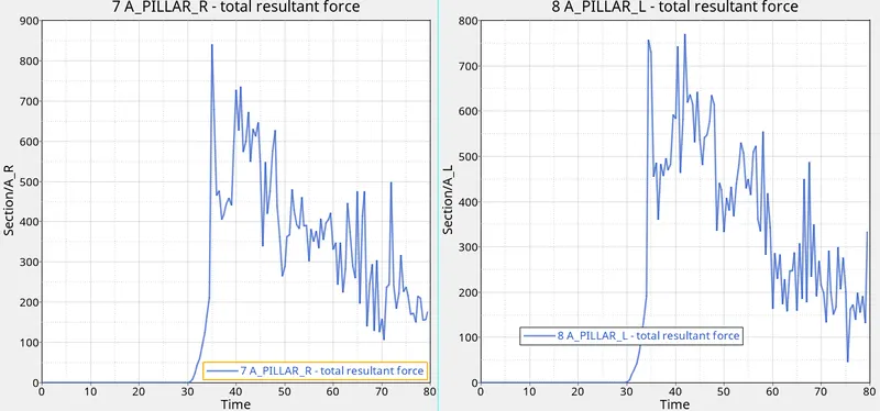
A pillar cross section forces. Max of 845N on left A pillar and 770N at right A pillar are observed.
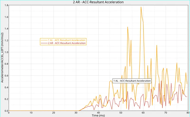
Acceleration curve received on the accelerometer at base of B pillar (on B pillar rocker) (AL - Accelerometer left; AR - Accelerometer right). Around 1.79 mm/ms2 is obtained for left accelerometer and 0.51 mm/ms2 is obtained for right accelerometer.
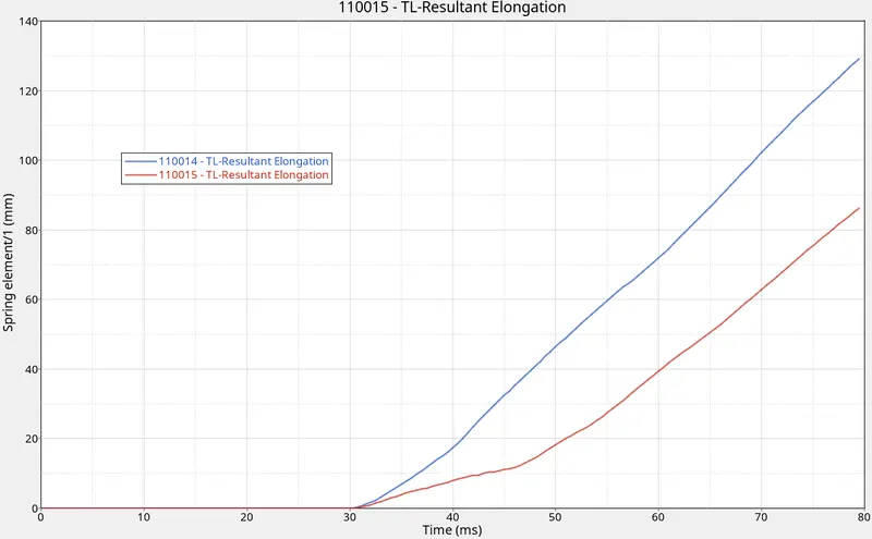
Intrusions on the dash wall 66695,66244. Total elongation obtained for 1st spring i.e. at node 66695 is 129 mm and for 2nd spring i.e. at node 66244 is 86 mm.
Conclusion: The simulation of a frontal car crash has been successfully done with the given boundary conditions and following energy plot for internal energy, kinetic energy, contact energy, hourglass and total energy. The hourglass energy is less than the internal energy which is great. When the crash simulation starts the internal energy and kinetic energy are constant and after 27 secs i.e. when the car crashes the rigid wall the kinetic energy reduces because the kinetic energy depends on the square of the car velocity. The internal energy is also seen to be increasing because during crash a lot of energy is generated when the elements are crushed. Due to this total energy seems to be constant. Very slight increase in the contact energy is also observed.
Also, in the graphs we can see that there is rise in sectional forces when the components crash the rigid wall at less ms when compared with each other i.e The first force will be acting at the bumper rails coming from the bumper at 26ms and then at the shotgun and the rails at 28 or 29ms and then at the pillars after 30ms.