Assignment 6-Frontal Crash Simulation Challenge
OBJECTIVE OF CHALLENGE: Establish a given model for frontal crash analysis by optimizing with given requirements and request required outputs and plots after running simulation.
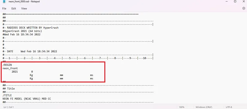
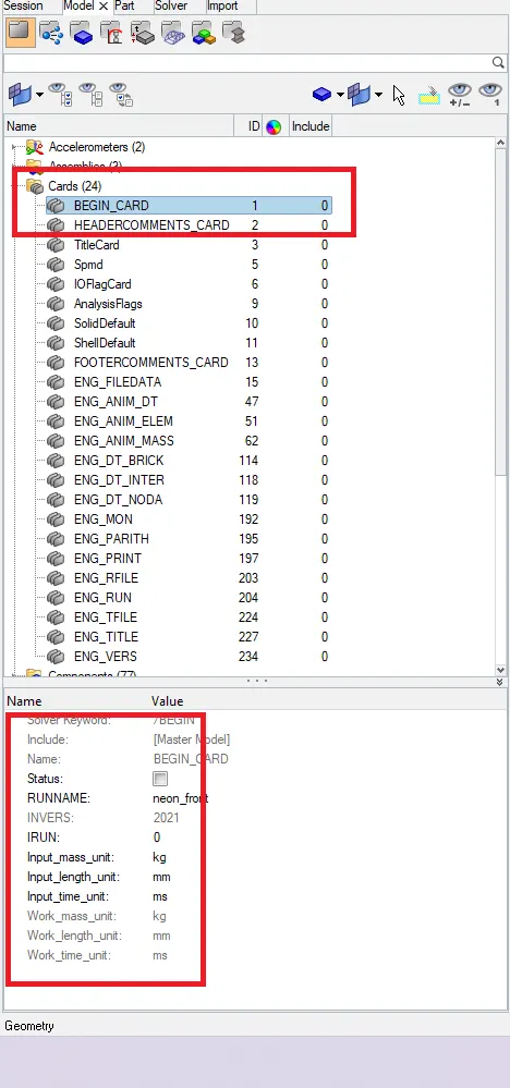
- Opened that given file (NNN_0000.rad file) in notepad observed units written below /BEGIN and kept as [Kg mm ms] for unit consistency. Or the other way goes to solver browser---->control cards--->open Begin card. we can see units there too
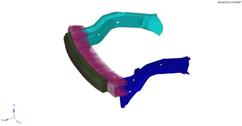
- Contact interfaces are defined in groups for body and found that in contact interface named 'structure radiateur' which is defined is an extra type7 contact to the body. The same part has already had a contact named as auto 'auto imp avg', 'auto imp avd' of type7. So, therefore, deleting 'structure radiateur' in the contact interface. And giving friction value for all contact interface as 0.2. And to know axial forces a type7 interface has been created with OB-BUMPER_FT_FOAM SHELL and CH-BUMPER-FT as shown in the figure below.
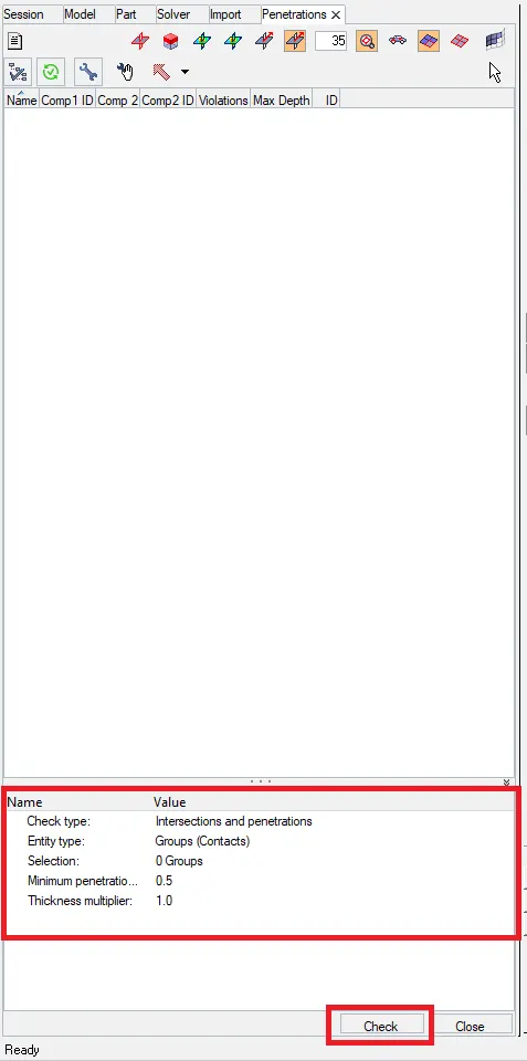
- To check penetrations and intersections Tools---> penetration check----> In model browser bottom selecting check type to intersections and penetrations---->Entity type to components---> next on clicking selection----->select from the list clicking on it selecting all components to run a check. keeping minimum penetration to 0.5 and leaving the remaining to default. On running check a message pops up as 'All interference check completed:0 collisions found' if none found as in this case. Changed entity type to elements--->selected elements from panel----->select all elements of the model and run check with keeping penetration .5. And later changed entity type to groups and selected from a list selected all that appeared in the list and with minimum penetration 0.5.by running check for both entity types message pops up as 'All interference check completed:0 collisions found' at the bottom. Hence we can conclude that there are no penetrations in this given model. (note: checked with penetration value 0.1, still, no collisions found).
- Here there are two spherical joints with Id 110013 and 110002, which are defined in the complete body for brake pedal moment it is unnecessary in here so it is deleted.
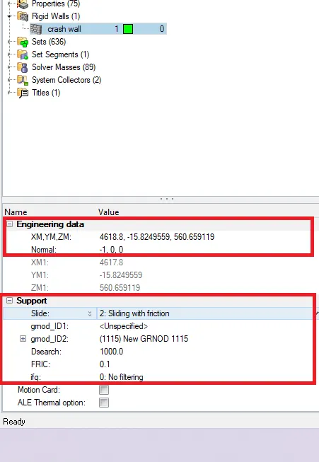
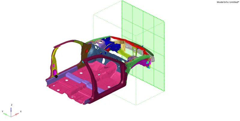
- To create a rigid wall two ways are possible, a)clicking: View---->Browsers--->Hypermesh---->solver and keeping the cursor in model browser left-click----->create--->RWALL--->plan. Orb)clicking on BCs--->create---->rigid walls after creating name it as 'crash wall' and in engineering data giving co-ordinates where the wall can be placed just before bumper of car body here co-ordinates are taken as 4618.8,-15.82,560.65 (XM, YM, ZM) and in support changing slide(sliding flag) to 2(sliding with friction) and giving friction value as FRIC=0.1. A rigid wall is created as shown below.
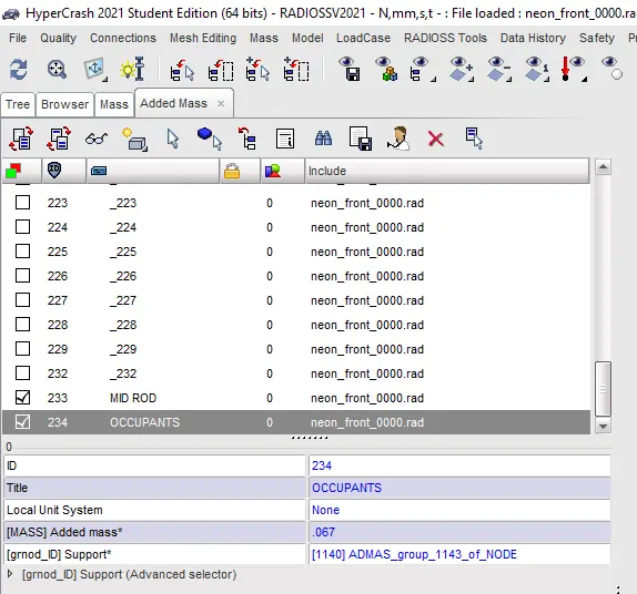
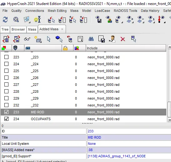
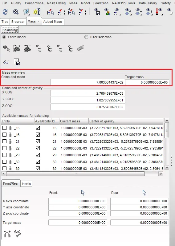
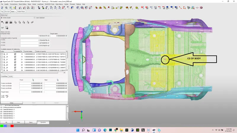
- Here the weight of the body is 188 kg so the CG of the body is at the gearbox area whereas the complete 300k nodes model is approx.1200kg so the mass is added to the body to place the CG as of original.
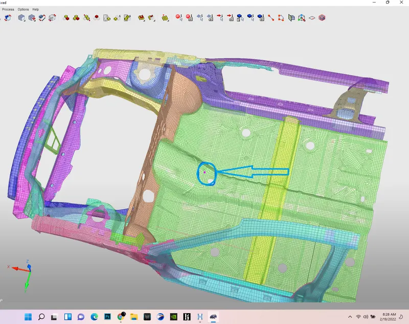
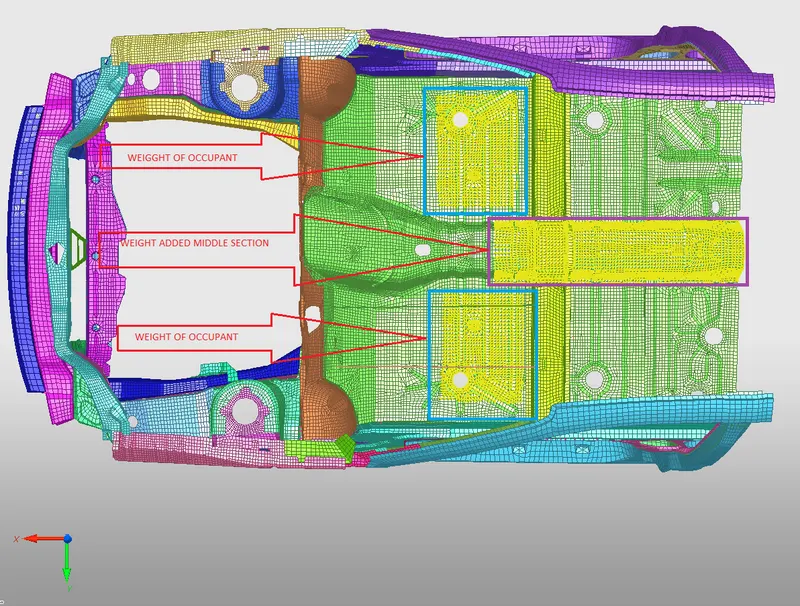
FIGURE: CG of the car before admass FIGURE: SHOWING PLACES WHERE MASS IS ADDED
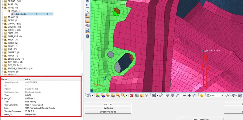
- To apply velocity clicking:View---->Browsers--->Hypermesh---->solver and keeping cursor in model browser left click--->create--->Boundary conditions----->INVEL--->move cursor to grnd_ID right click and click on create---->now click on Entity IDs----->click on nodes--->select nodes of displayed---->click proceed.Then a value of 15.64 millimeter per millisecond is given in velocity component as per unit converstion(35 mph = 15.6 mm/ms).
- To check model On top we can see tools option---->Model checker---->Radioss Block. On hitting Radioss block Errors, Warnings and info pop up in the model browser. In my case(given model) there are 0-errors,5-Warnings and 9-info. The parameters that are in warnings and errors if it is valid in status green tick shows up if it is not included a dash and if it disturbing model a red x symbol which we have to rectify for making model good quality.
| Warning in this model operation | Operation to fix this warningsIdel |
| Idel is not equal to 1 or 2 for interface type7 |
So, as per recommendations, Idel value changed to 2. |
| Free 1d elements. | Deleted unused |
| Unused sets. | Ignored |
| Rigid bodies have free ends | rigid body at shown in below figure has deleted |
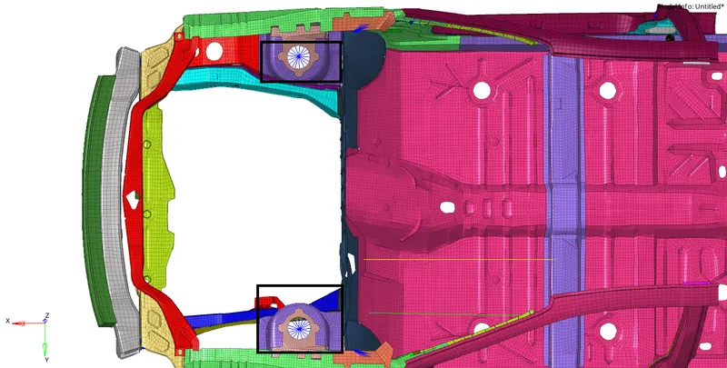
After solving these when rechecked a message pops up as No failed entities found in the section.
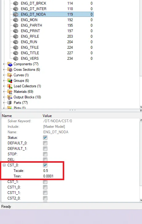
- To enter time click on control cards in the model browser search for a card named ENG_DT_NODA. Click on it, expand CST_0 in there give Tscale as 0.5.
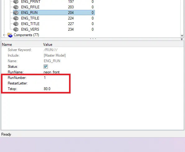
- To enter termination time of simulation model browser--->control cards in the model browser search for a card named ENG_RUN and give Tstop as 80 seconds.
OUTPUT REQUEST:
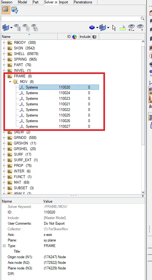
- To see a cross-section of parts a reference of move frame has to be created so when creating cross-section a reference frame is created hereby solver browser--->create---->Frame---->MOV and node are selected as per cross-section plane. The cross-section will use this reference frame to calculate data. Create sections In the left and right rail as shown below and select two rows of elements and also crate reference frame with node data. For Axial force define a type7 interface and add in TH file in INTER section.l
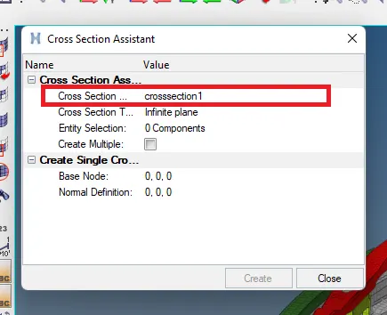
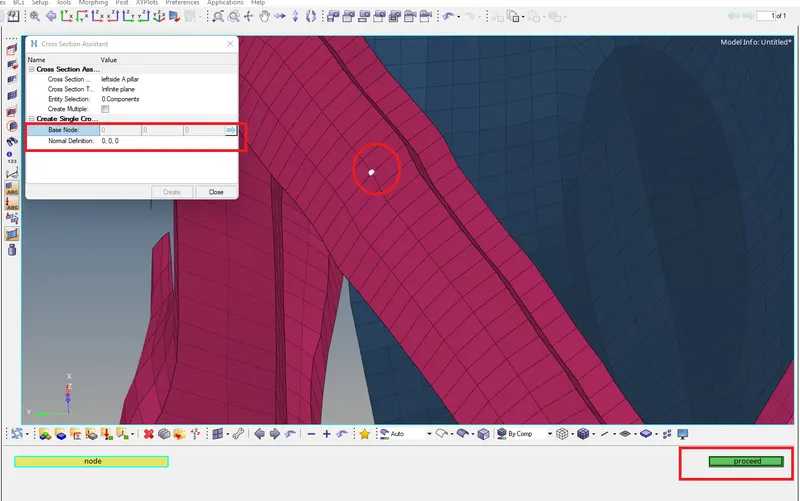
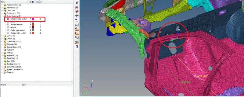
- create a section for a pillar by left click in model browser create--->cross section enter. Then a dialogue box appears asking for node data and Normal data this we are creating at A-pillar cross-section so changed the name from crosssection1 to 'left side A pillar'.Chose a node on the pillar by clicking the arrow button at the end and enter proceed and next choose a normal direction on A-pillar and enter proceed.
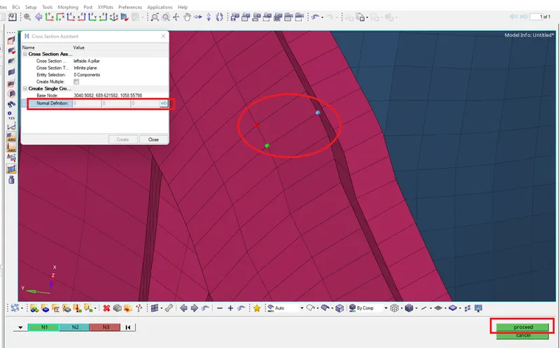
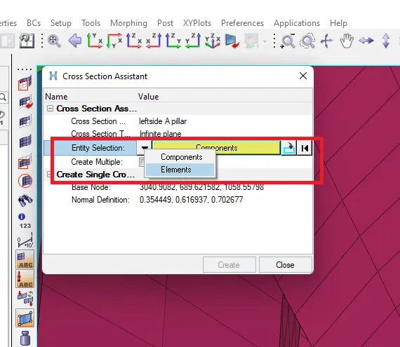
- Now we select entities in Entity selection place the cursor on Entity selection left-click--->change components to elements after selecting click on elements to select from the panel and select element of 2 or 3 rows as shown in below figure.
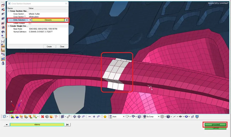
- After hitting proceed a cross-section is created pillar shown below. We will create a crosssection at A-pillar right side and on shotgun(left and right), Rail(left and right) and include them in TH under SECTIO.
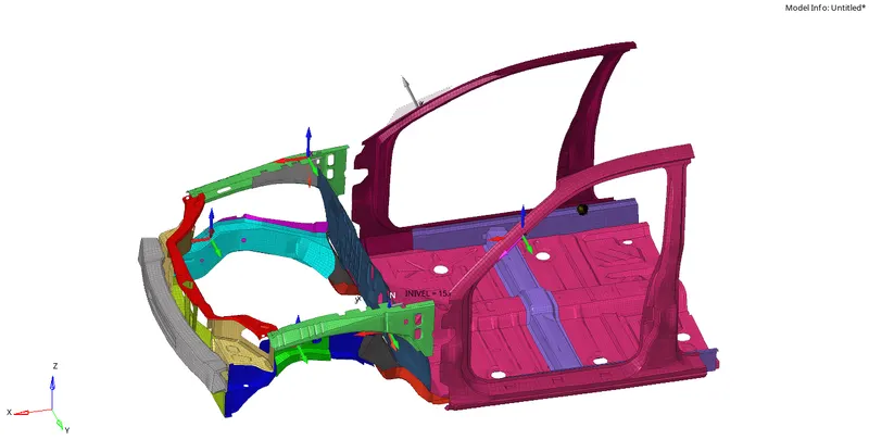
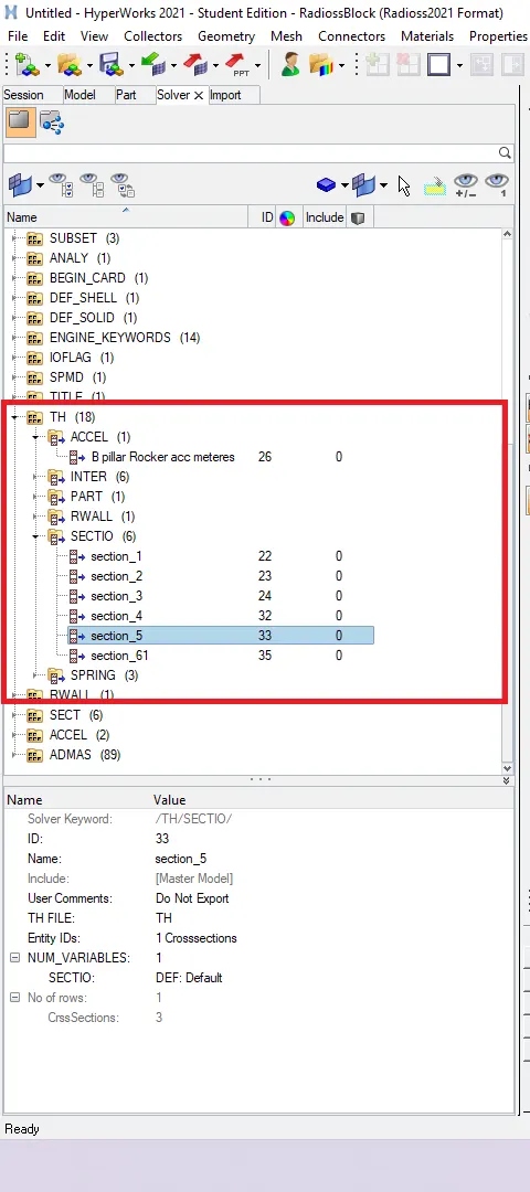
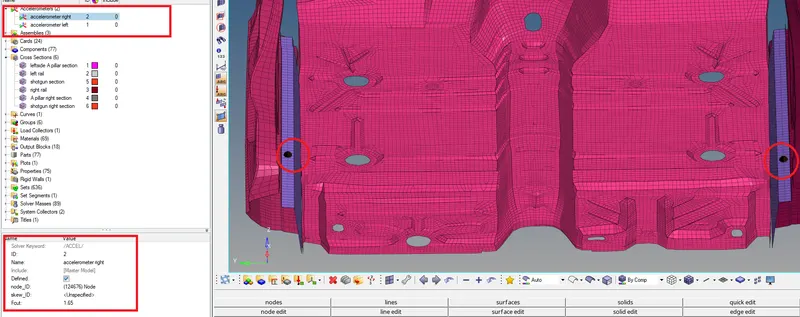
Create accelerometer Model browser--->right click--->create--->Accelerometer---> click on a node Id and select any two nodes one on Right and one on left of B pillar rocker arm. And add in TH file of keyword ACCEL and include entities.
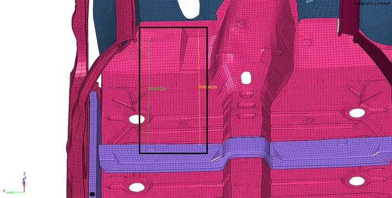
For Intrustions 1D panel springs pick node 66695 and the second node perpendicular to it which is near the B pillar rocker. Repeat the same step with 66244.
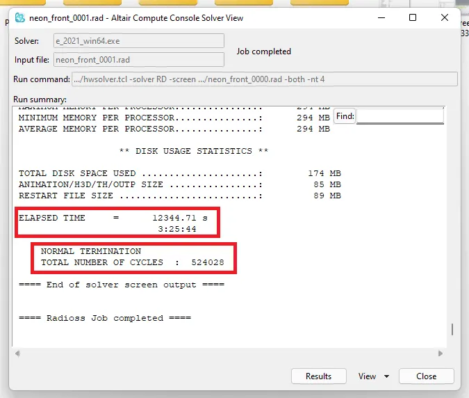
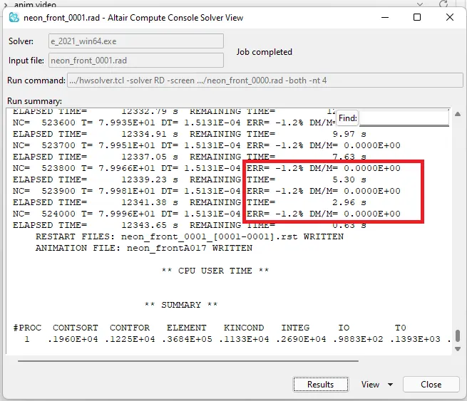
CONCLUSION AND RESULT: The model is analyzed as per the given requirements the deformation occurred at the front section as shown in the figure below and the displacement increased over time and internal energy and external energy coincided as time passed. The internal energy loss is max,min (0%,-1.2%) and mass error is (0.000E+00) or 0%(on multiplying 100).
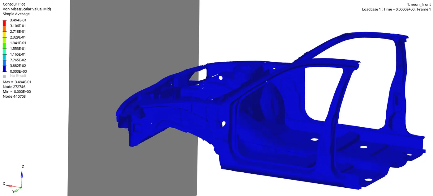
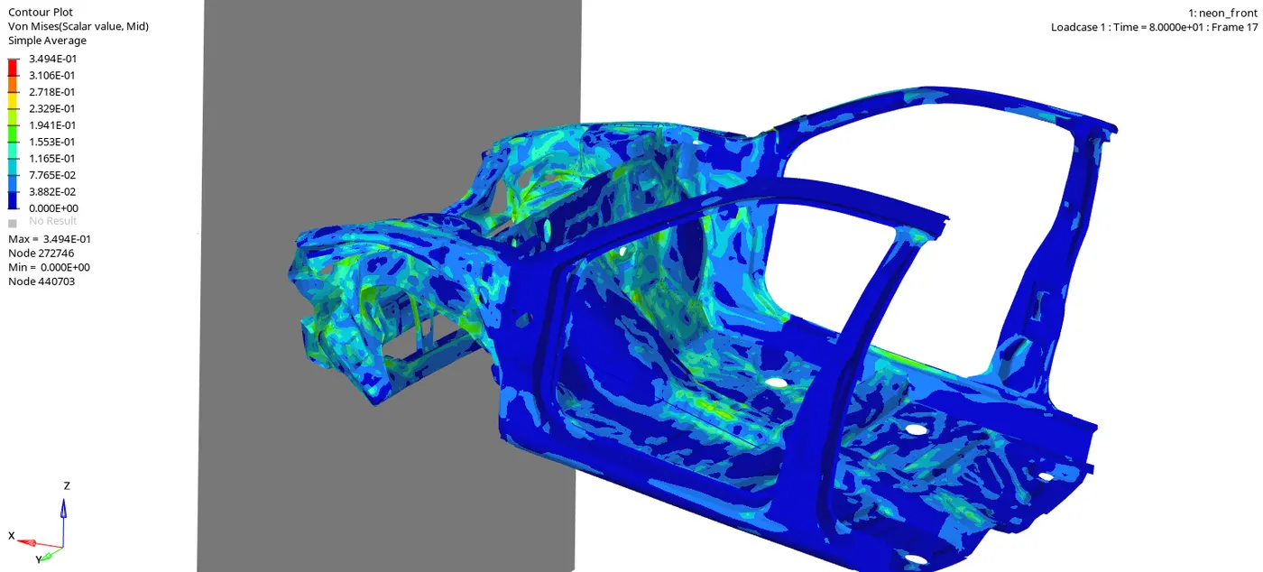
Here the crash is a bit different as the mass added to the middle section of the floor body(CH-CBN-FLOORBRD-FT) when the body has to roll over a little bit the mass that is added is counteracting and the front section undergoes crushing. But in a real case scenario, the mass is added backside where occupants are situated.