Assignment 6
Objective:
To understand the basics of a turbocharger and simulate a 6-cylinder turbocharged DI engine and a 4-cylinder VGT engine and list down their working paramters.
Basics of a turbocharger:
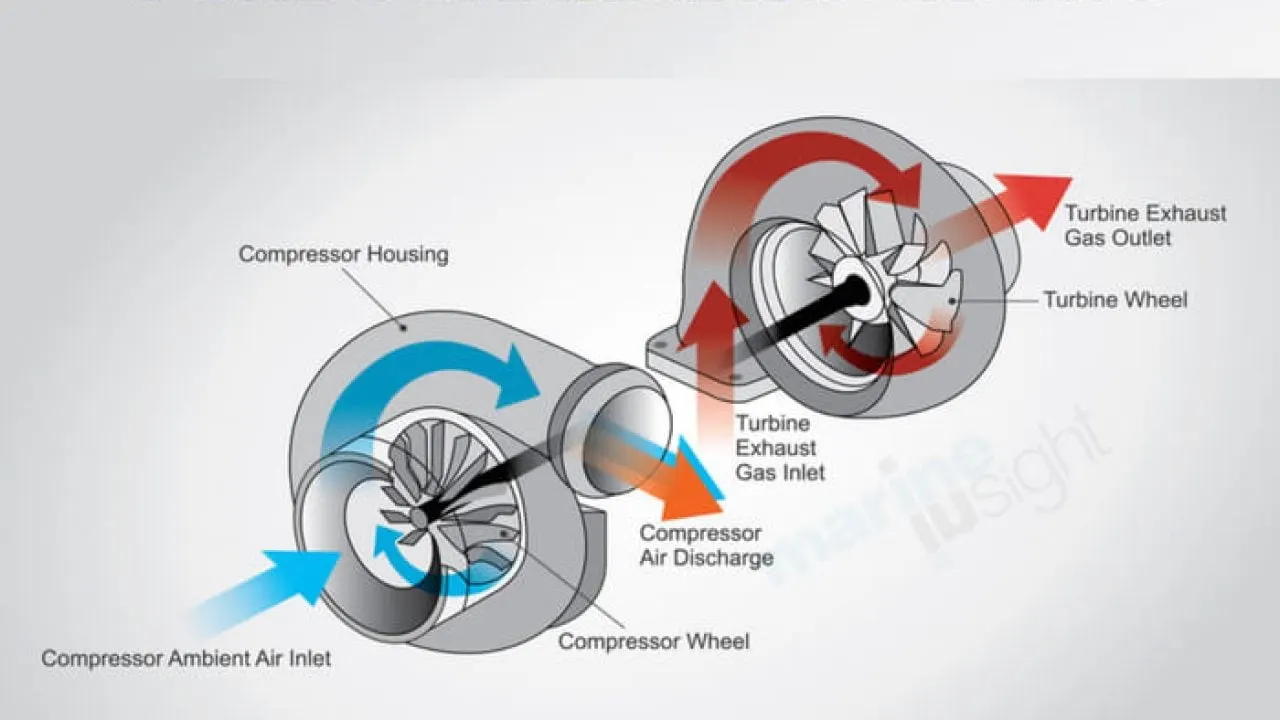
A turbocharger uses engine exhaust energy to breathe more air into the combustion chamber for a more efficient engine operation. Different types of turbochargers are:
1. Fixed geometry turbocharger:
The simplest turbocharger design from a control perspective is one whose turbine and compressor geometry are fixed and that uses no means to control boost pressure. The boost pressure provided by this type of turbocharger is entirely determined by the engine exhaust flow and the characteristics of the turbocharger. The turbocharger is optimized for a particular operating condition. Turbocharger turbine size and air ratio tend to be relatively large for a given application because of the need to size the turbocharger so that at the highest flow conditions, the turbocharger does not overspeed or provide excessive boost pressure. While boost pressure near rated conditions can be selected via turbocharger sizing, transient response and boost pressure at lower engine speeds can suffer. Also, at high altitudes, turbocharger speeds would tend to increase which could lead to problems with surge and/or turbocharger overspeeding unless accounted for by oversizing the turbocharger. However, for some engine applications operating primarily at a limited number of steady-state conditions, an uncontrolled turbocharger with a fixed geometry turbine can prove entirely satisfactory.
For applications that experience a wide range of operating conditions and that must provide good dynamic response, for example in passenger car applications, a fixed geometry turbocharger with no control of boost pressure is unsuitable. Method used to control boost pressure for turbochargers with fixed geometry turbines in these applications are:
- Exhaust side bypass, also known as a wastegate, to bypass some of the flow from the turbine inlet.
2. Wastgate turbocharger:
The wastegate valve prevents the turbocharger from over-running. Particularly, it also avoids the engine from over-boost and prevents any mechanical failure. This feature in the turbocharger consists of a bypass valve. It circumvents some part of the exhaust gas going to the turbine and releases them into the outlet. Furthermore, the waste-gate turbocharger has a bypass valve built into the turbine housing. It diverts some of the exhaust gases away from the turbine wheel through this valve. The exhaust system automatically routes the bypassed exhaust gases to the catalytic converter and tailpipes. In this system, the speed of the turbine wheel determines the diversion of the exhaust gases. Besides, the wastegate unit reduces the high boost pressure developed by the compressor to the desired level. Thus, it delivers optimum engine performance with controlled peak cylinder pressure.
3. Variable geometry turbocharger:
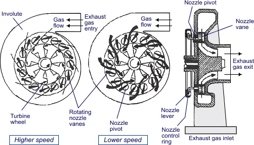
Perhaps one of the most exceptional forms of turbocharging, VGTs are limited in production (though fairly common in diesel engines) as a result of cost and exotic material requirements. Internal vanes within the turbocharger alter the area-to-radius (A/R) ratio to match the RPM. At low RPM, a low A/R ratio is used to increase exhaust gas velocity and quickly spool up the turbocharger. As the revs climb, the A/R ratio increases to allow for increased airflow. The result is low turbo lag, a low boost threshold, and a wide and smooth torque band. The peak efficiency of a variable geometry turbine occurs at about 60% nozzle opening. It is usually comparable to or a few percent lower than that for a fixed geometry turbine. However, efficiency drops off rather quickly as nozzle opening is reduced or increased from a mid-vane opening position.
4. Electric turbocharger:
An electric turbo is designed to blend the performance and efficiency of a turbocharged engine with the responsiveness of a supercharged engine. They are built to eliminate turbo lag, which turbochargers can suffer from but superchargers do not.
To achieve this, an electric turbocharger features a small electric air compressor run by a powerful motor. When the driver presses on the gas pedal, the air compressor will instantly force cold air into the engine, and this action should ensure power is delivered smoothly even before the exhaust gas-reliant turbo has gotten up to speed.
When the main turbo is up to speed and able to provide its power boost, the electric system running the air compressor will shut off in order to save energy.
6-cylinder DI engine:
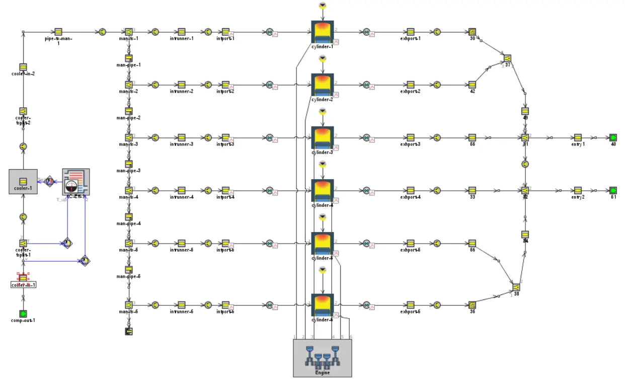
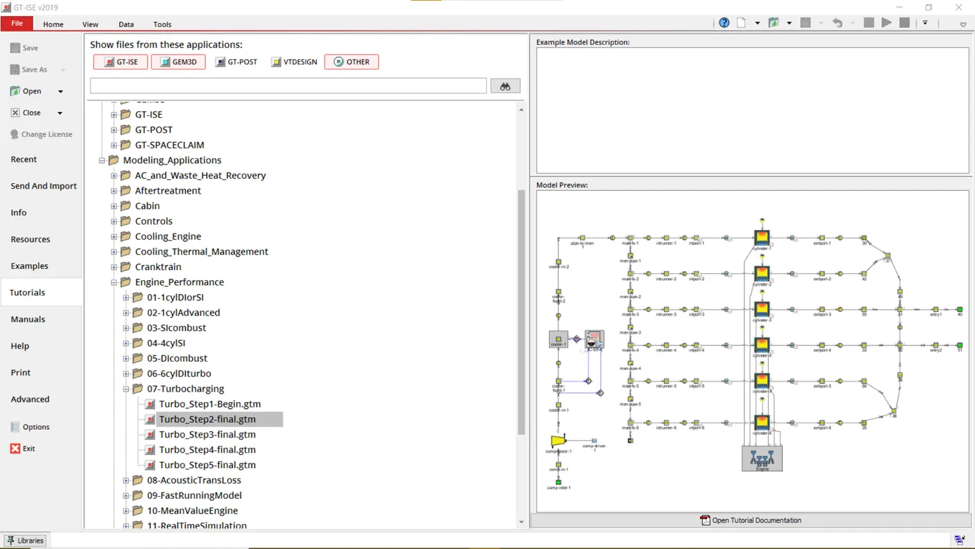
In the above 6-cylinder Di engine model, the exhaust gases were guided towards the turbine inlet but the turbocharger had not been modelled here. As seen from the model, there is no physical compressor or turbine present in the whole model.
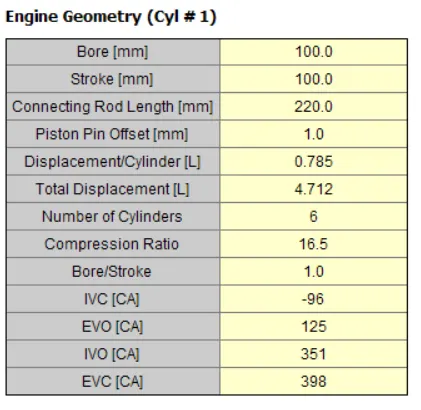
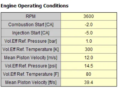
Hence, this is a 6-cylinder DI engine without turbocharger. This model is simulated at 3600 RPM.
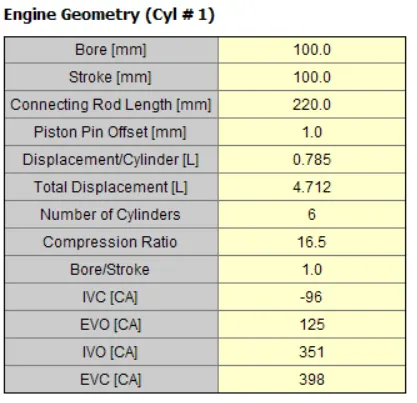
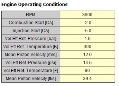
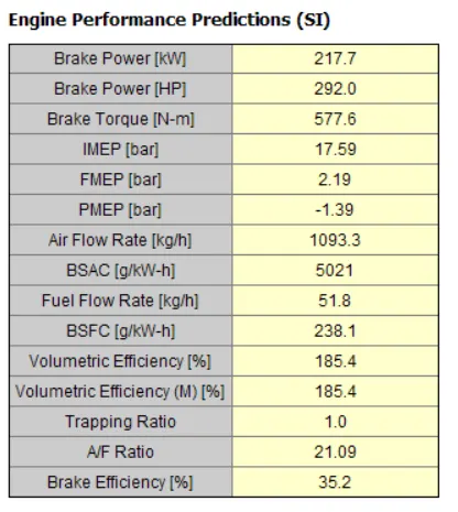
6-cylinder Turbocharged DI engine:
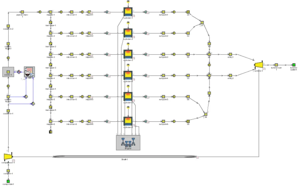
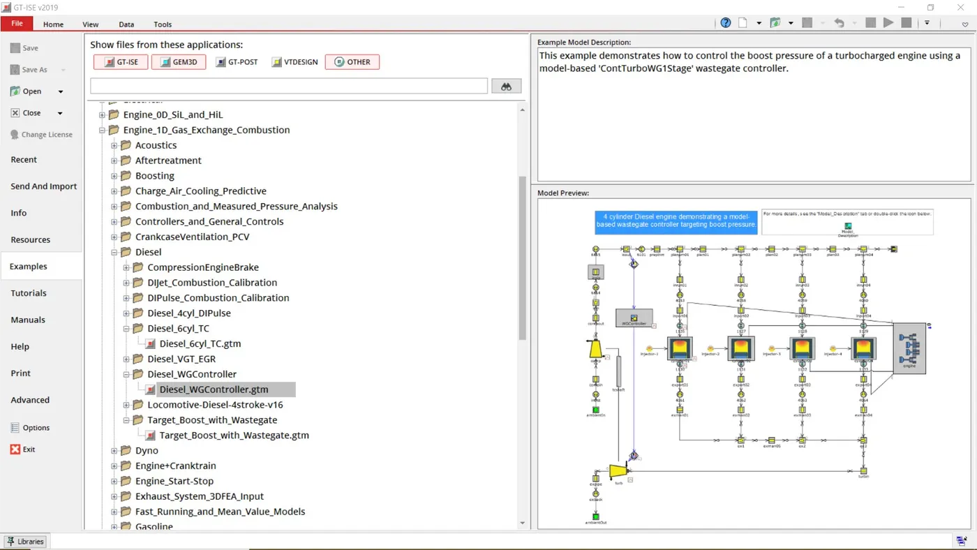
In this model, a wastgate turbocharger has been modelled with all the necessary inputs required in a turbocharger.
This model will be simulated at 3600 RPM.
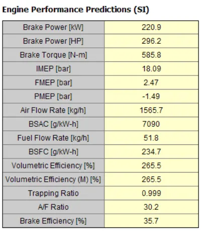
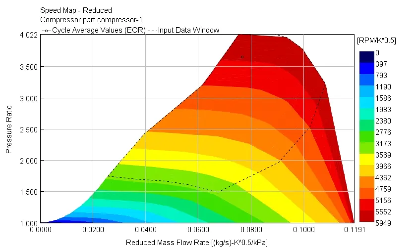
Working pressure ratio of the compressor was 3.6544566 bar.
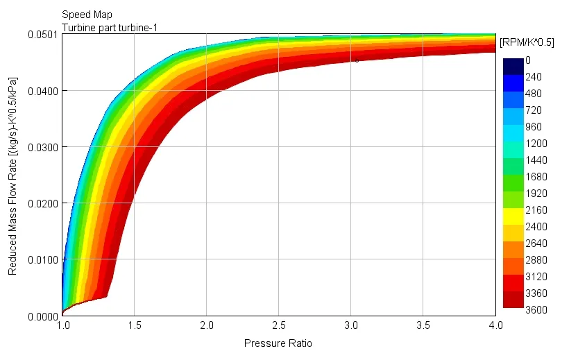
Wprking pressure ratio of the turbine was 3.043763 bar.
Hence, the increase in the output pressure from the turbocharger was 0.6106936 bar.
4-cylinder DI engine with VGT:
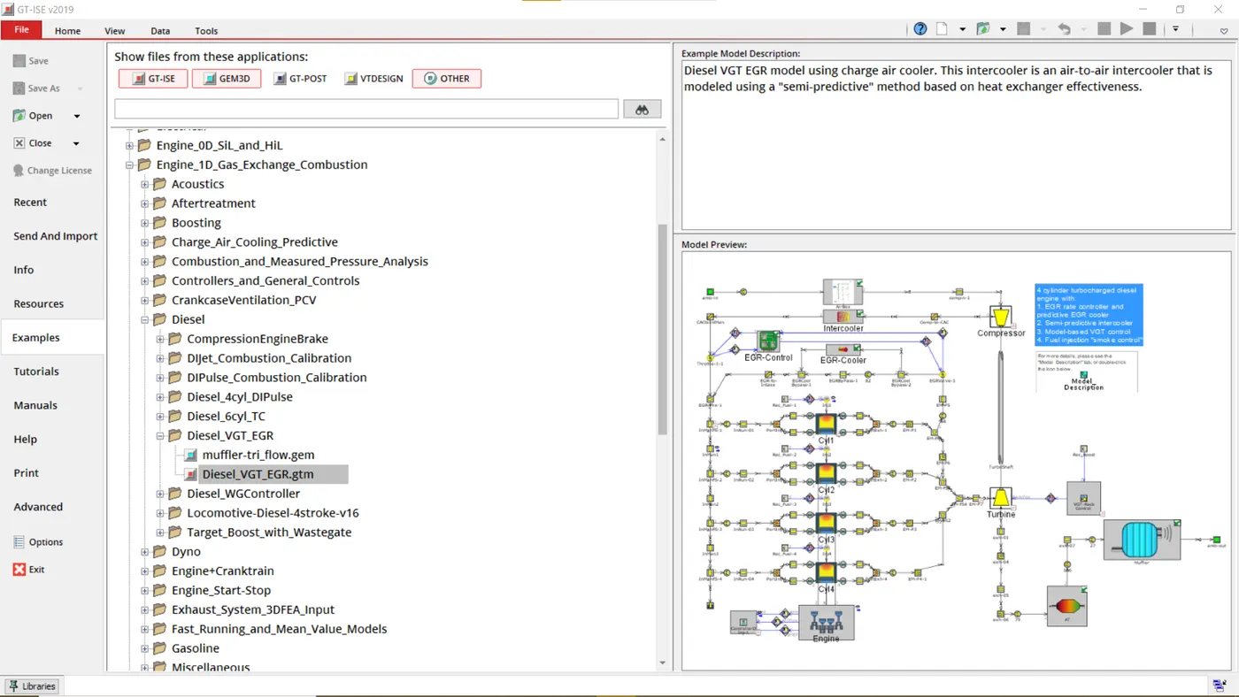
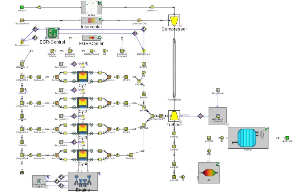
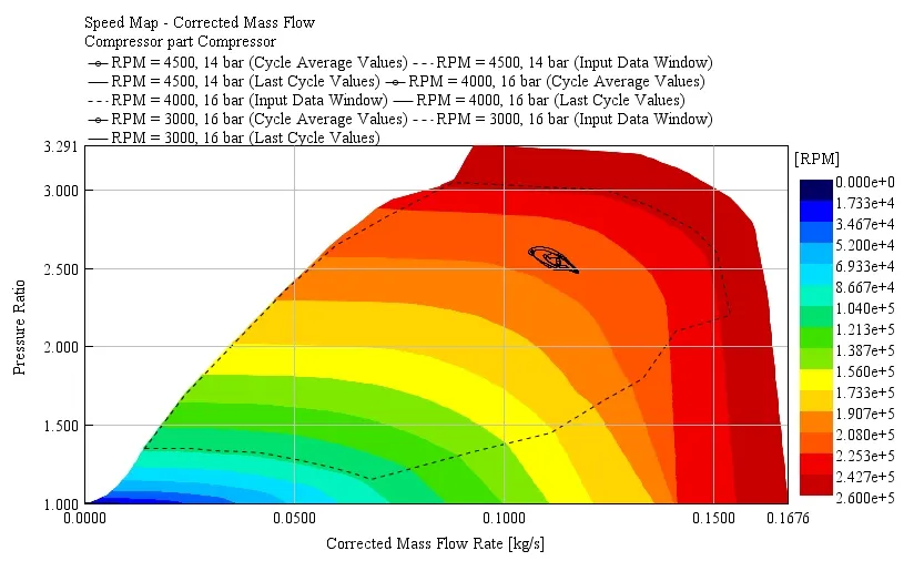
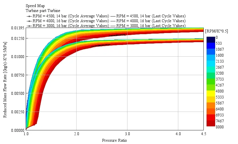
The example 'Diesel_VGT_EGR' demonstrates several modeling concepts important for automotive diesel engines, including variable geometry turbine, boost control, intercooler, EGR circuit with cooler and EGR rate control, injection limiting for smoke control, and exhaust after treatment device modeling.
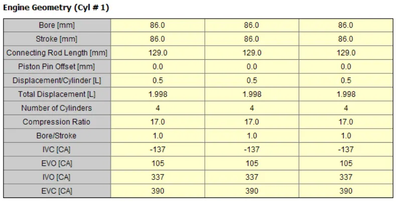
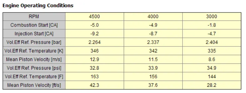
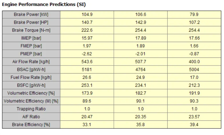
The engine is a 4-cylinder, four-stroke, direct injection, 2L diesel engine. the engine speed is entered by the user and the engine torque is calculated. Combustion is modeled by the DIPulse method, a predictive combustion model using the detailed injection profiles. In-cylinder heat transfer is modeled using the Woschni model. A FE model is used to predict the cylinder, head and piston temperatures. This simulation will run until it reaches steady-state convergence for six different engine speeds at full load, three part load operating points, and an additional idle point (total of 10 cases).
The intake system consists of the air piping upstream of the compressor inlet, and contains a simple model of an air box. The air box is modeled as a group of interconnected flowsplits that represent the total volume of the air box. At the inlet and outlet of the air box, "bellmouth" orifice connections are used to model smooth transitions.
The intercooler is found downstream of the compressor outlet. This intercooler is an air-to-air intercooler that is modeled using a "semi-predictive" method based on heat exchanger effectiveness.
Conclusion:
Variable geometry turbochargers are used to improve acceleration, reduce turbo lag and improve power output especially at higher altitudes and humid conditions. Being really expensive, VGTs are used only in high-end luxury vehicles. Hence, a wastegate turbocharger is much more viable option to use in DI engine to improve its performance.