Frontal Crash simulation of Dummy car model using Radioss
OBJECTIVE
Perform a frontal crash simulation of a given BIW of a car against a rigid wall using the following sets of instruction
- Use a consistent unit system of kg-mm-ms
- Assign proper interface with a friction coefficient of 0.2 and recommended parameters
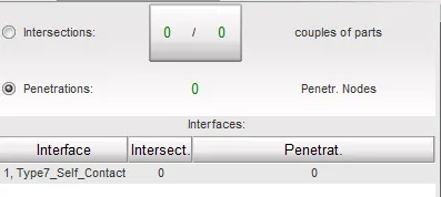
- Ensure no penetration and intersection
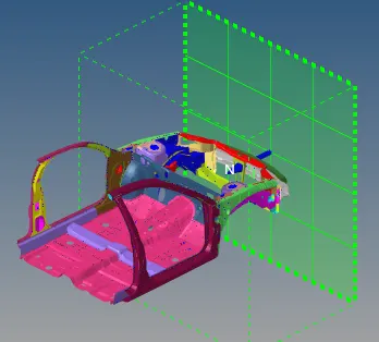
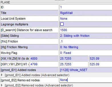
- Rigid wall with friction coefficient 0.1
- Add mass to the given model such that the final mass is approx. 700 kg and CG is in its desired position.
- Initial velocity = 35 mph
- Ensure good quality using a model checker
- Timestep of 0.5 to 0.1 ms
- Simulation time = 80 ms
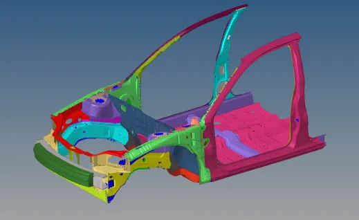

Extract the following data from the simulation
- Cross-sectional force on the rail
- cross-sectional force on the shotgun area
- cross-sectional force on A-pillar
- cross-sectional force on hinge pillar
- Axial force received on rails from bumper
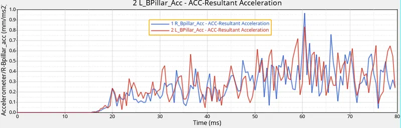
- acceleration received by the accelerometer at the base of the B pillar
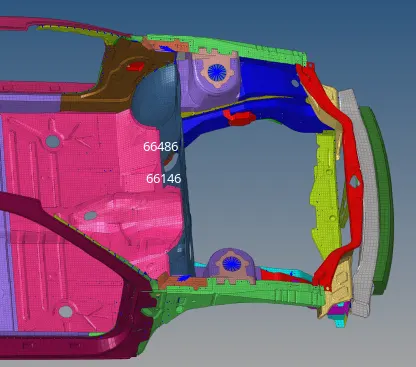
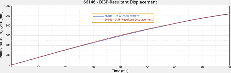
- intrusion on the dash wall (near acceleration and brake pedal)
PROCEDURE

| 1 | Bumper |
| 2 | Rail |
| 3 | Hinge Pillar |
| 4 | Shotgun |
| 5 | Fender |
| 6 | A-pillar |
| 7 | B-pillar |
The study was executed following the below-mentioned steps. The steps discussed are focused on performing the frontal crash simulation and these may change depending upon the kind of simulation at target.
Step 1 - Model Cleanup
- Since the model is a raw cut out from a larger model, there are few unwanted entities like joints, interfaces, surfaces, nodes, etc. The first step is to identify these elements and delete them if not required.
- Hypermesh -> Tools -> Empty -> select -> delete = to see the empty entities and select and delete.
- Hypermesh -> Tools -> Unused = unused entities in the model, select and delete
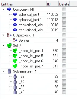
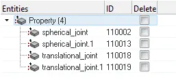
Step 2 - Interface delete
- Since the model is a cutout from the larger model, the older interfaces are still defined. Which is not required for our current study, so delete these interfaces
- Hypermesh -> Solver -> Interface -> select all (6 interfaces are defined previously) -> delete
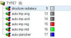
Step 3 - Defining Interface/contact
- Since we are targeting the frontal crash simulation against a rigid wall, we only have to define a self contact card.
- Type 7 contact card is defined with the recommended parameters from crash applications.
- Hypermesh -> Solver -> Interface -> Type 7
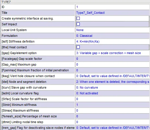
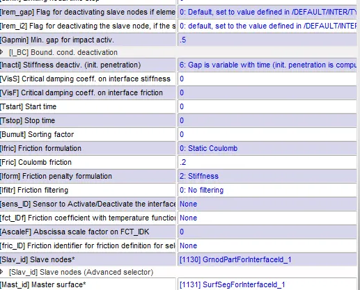
Step 4 - Mass addition.
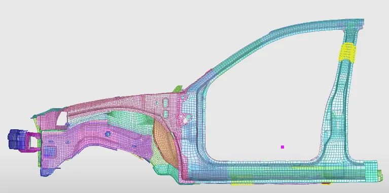
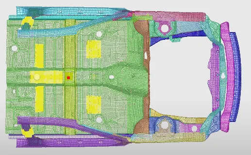
- Target mass = 700 kg and COG should be somewhere around the line of B-Pillar and bottom rail. Mass is added accordingly
- Hypermesh -> Solver -> Admas -> select the nodes and mass to be added.
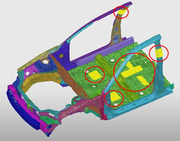
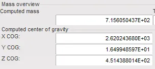
Step 5 - Boundary Condition
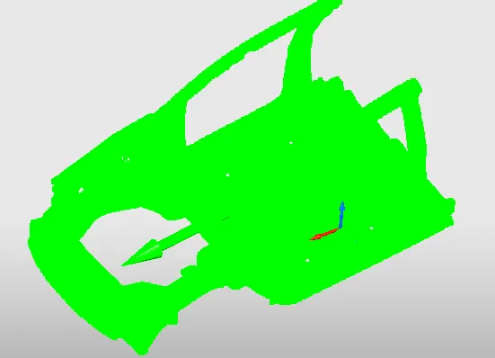
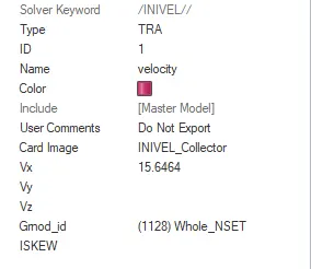
- the only boundary condition is initial velocity i.e. 35 mph or 15.6464 mm/ms
- Hypermesh -> Solver -> Boundary condition -> INIVEL -> define parameters.
Step 6 - Rigid wall
- Hypermesh -> Solver -> RWall -> select base point and normal direction
Step 7 - Section creation
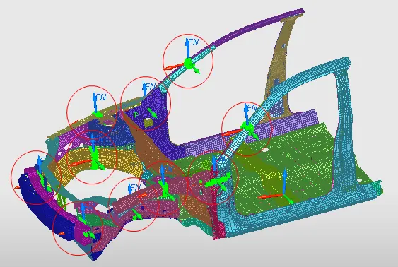
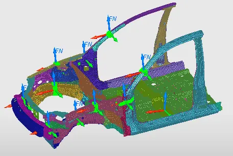
- It is important to check the forces in the sections to determine if the simulation is correct or not. Few sections are created across the model on both the sides
- Hypermesh -> Solver -> Section -> select the reference nodes -> select node group -> select elements enclosed in the selected node group
- A total of 10 sections were created as shown below
Step 8 - Accelerometer
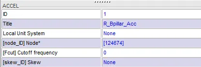
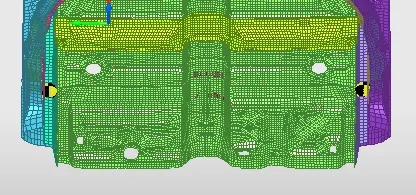
- In order to determine the acceleration at some point in the model, we require an accelerometer sensor. Here 2 accelerometer sensors are placed at the bottom of the B-pillar on both sides.
- Hypermesh -> Solver -> Acce -> select reference nodes
Step 9 - Output blocks
- After creating all the sections and accelerometers, we require the output from these entities. For this purpose, output blocks are defined stating what all results are to be extracted.
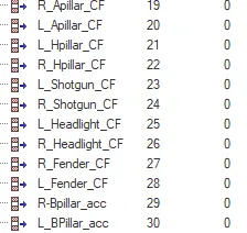
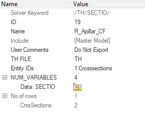
- Hypermesh -> Model -> Output Blocks -> select cross sections -> assign necessary output requests
- The below image shows the output request for cross-sectional forces from sections created and acceleration from the accelerometer.
Step 10 - Intrusion (around accelerator and braking pad)
- A local skew was created on a center rail using Hypermesh -> Solver -> Skew -> Mov
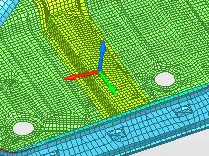
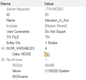
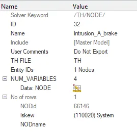
- Hypermesh -> Model -> Output blocks -> select nodes -> assign necessary output requests.
Step 11 - Run Model Checker
- Hypermesh -> Tools -> Model Checker -> Radioss Block or Hypercrash -> Quality -> Model Checker
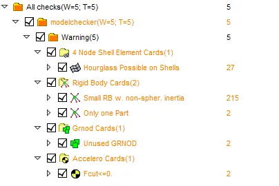
- Carefully remove all the errors without disturbing the model. Rectify the warning as much as possible and check if the remaining warning may affect the simulation or not.
Step 12 - Check initial penetration
- Hypercrash -> Interface -> Run check
Step 13 - Run the simulation
- Hypermesh -> Analysis -> Radioss
Step 14 - Evaluate the results
- Evaluate the results using Hyperview or Hypergraph.
- Check energy and mass error in the simulation.
RESULTS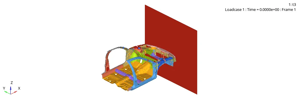
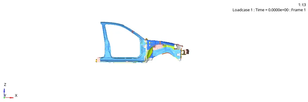
- Errors
The error in energy and mass are withing acceptable limits which shows that there is no unwanted behavior taking place during the simulation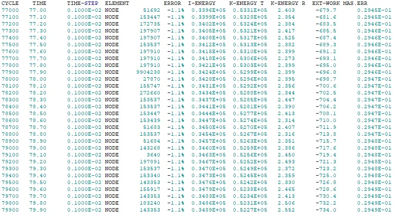
- Energy
Total energy remains almost constant, whereas the decrease in kinetic energy is equal to the increase in internal energy depicting the correct transfer of energy.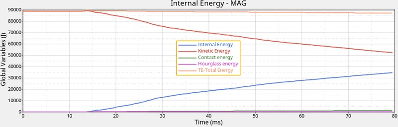
- Stress
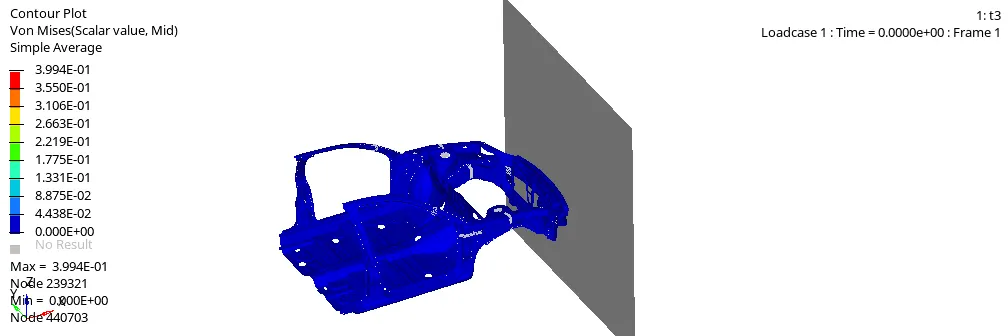
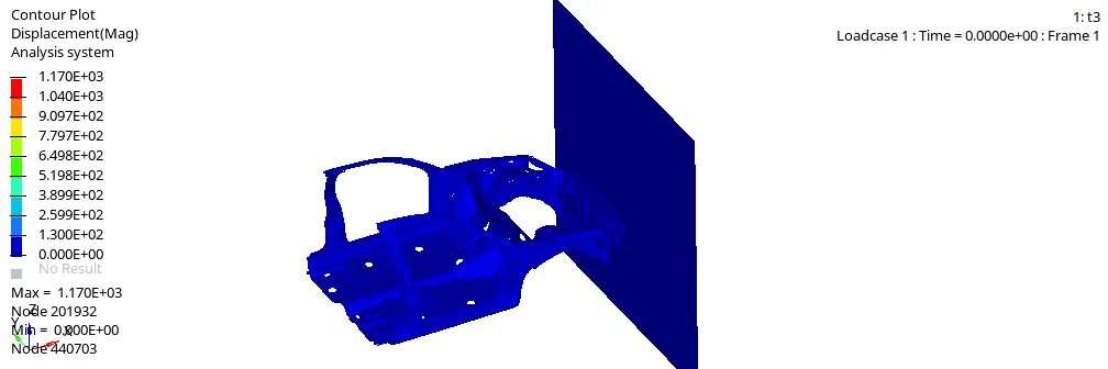
- Displacement
- Cross-sectional Forces (kN)
A-Pillar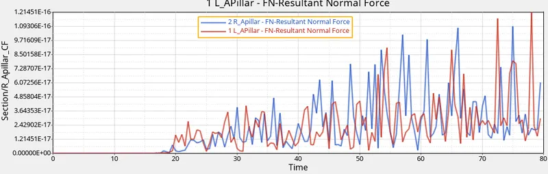
Hinge Pillar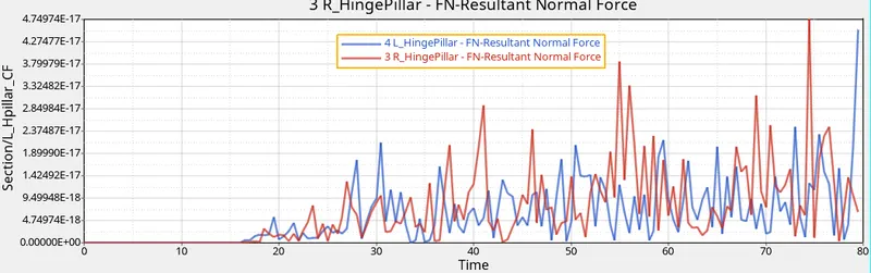
Shotgun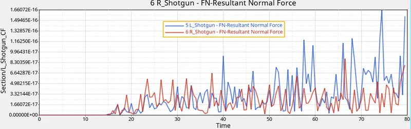
Headlight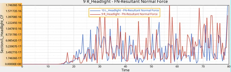
Fender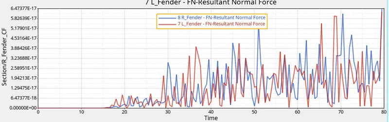
From the above-mentioned force, we can see that the max force is in the headlight region followed by shotgun, fender and Hinge Pillar. This is the order of components from the front and thus it confirms that there is the proper transfer of force due to the impact. - Accelerations
- Intrusion
CONCLUSION
The study helps us understand the typical process used in determining the frontal crash simulation. It helps us understand different outputs that need to be checked for an assessment of crash simulation results.