Assignment 5-RADIOSS Interfaces & Study of Effect of Notches Challenge
Aim: Create the 2D mesh for bumper assembly.Create a different type of interface, assign recommeneded values to interface and compare the base simulations setup results.
Objective :
- To generate the mesh for the given bumper component with the mesh size of 6mm.
- To change the parameters for the given crash tubes model as various cases.
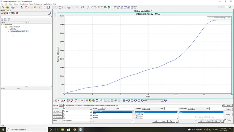
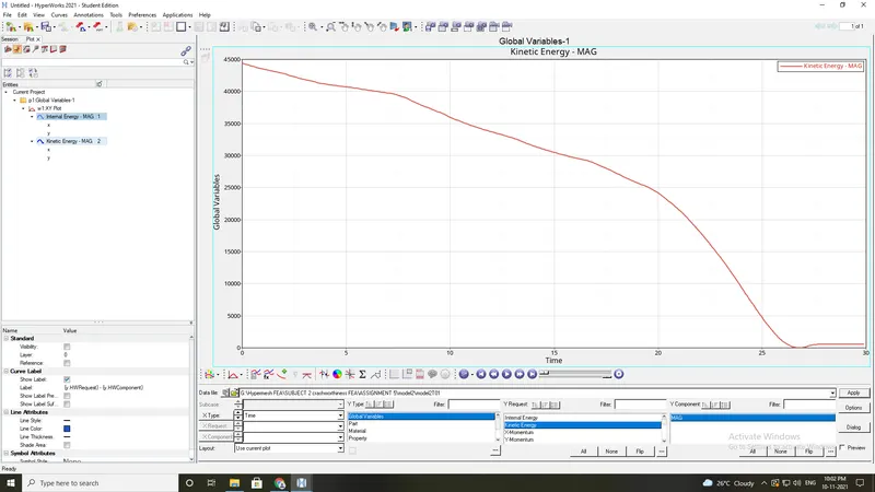
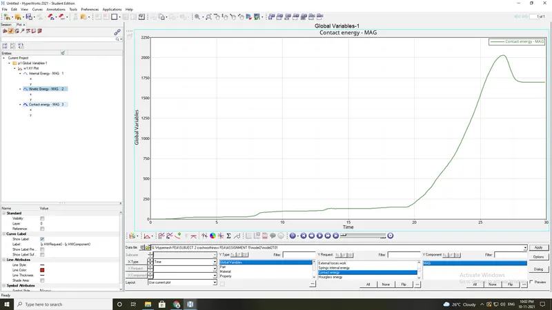
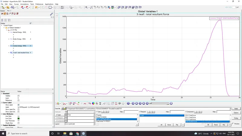
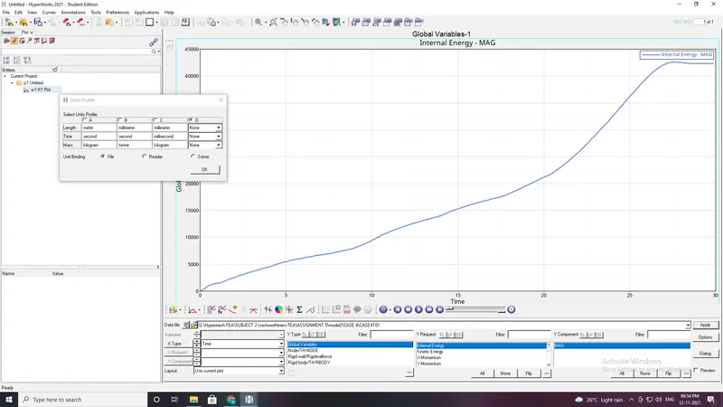
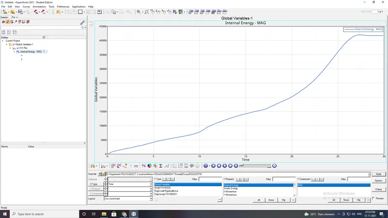
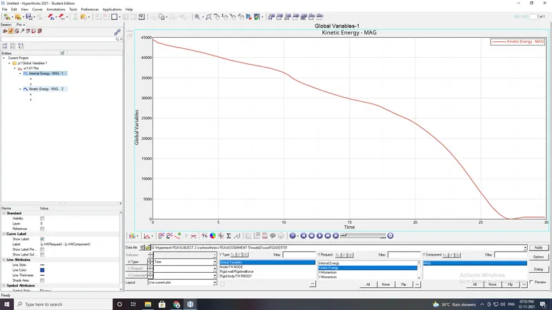
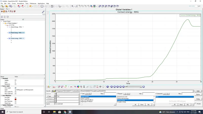
- To plot the graphs with RWALL forces , contact forces , internal energy(post-processsing)
MOdel 1: Meshing of bumper assembly
Import given model into hypermsh.
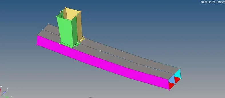
Assign quality parmeters:
- To give the criteria , click on the preferences in the standard menu bar
- to mesh select the automesh option from the 2D panel
- After the mesh is completed make sure the model does'nt have the tria elements .
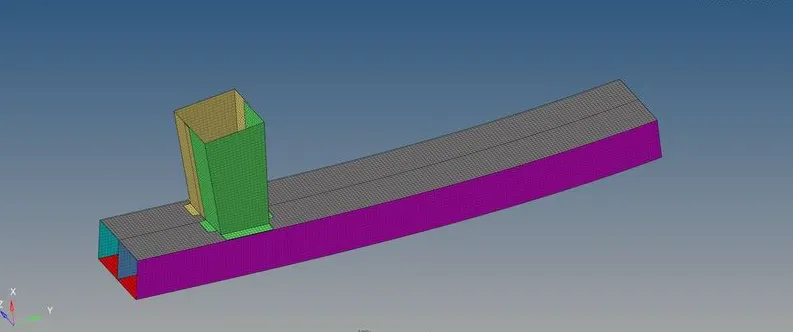
- giving a proper connection between the crash box and rear bumper.
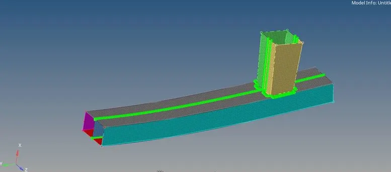
Model 2:
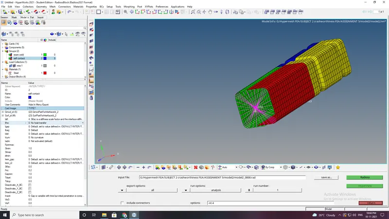
Case 1:Run the crash tube model as it is.
After the model is imported .The simulation needs to be performed without changes in model in this case.
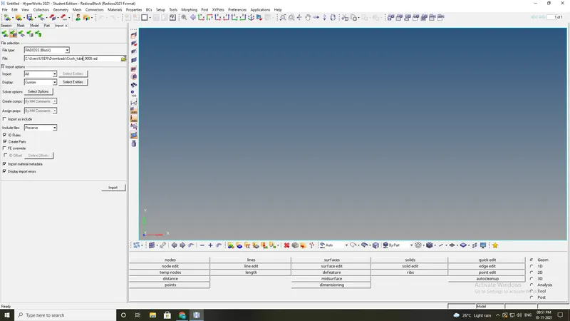
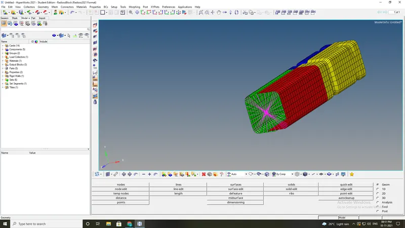
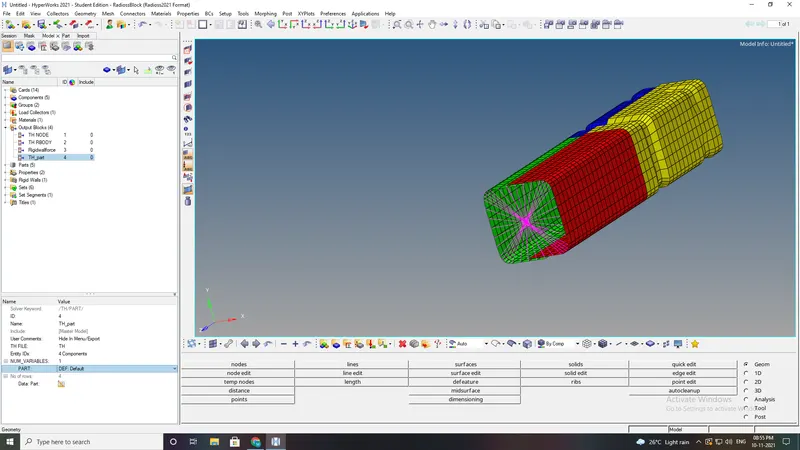
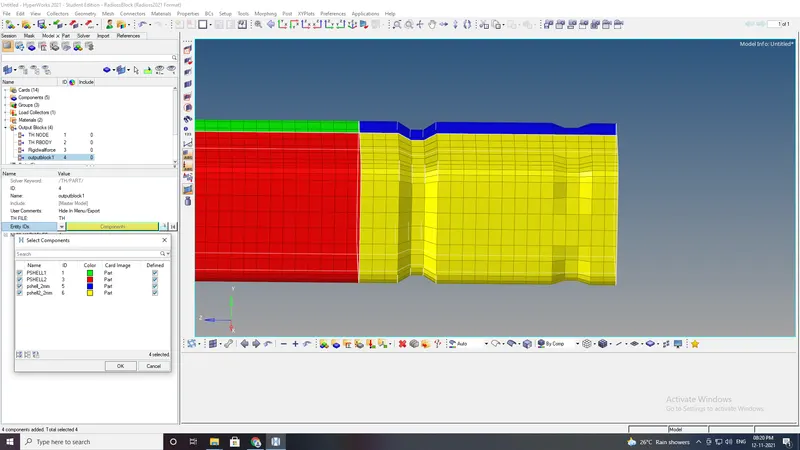
- In oder to create the THPART we have to click on the output blocks and create the TH PART in entity id .
- TH PART is created.
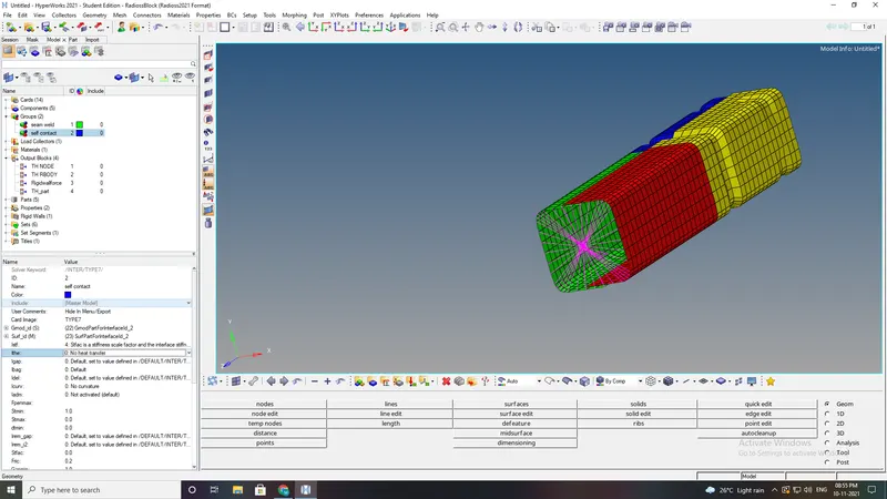
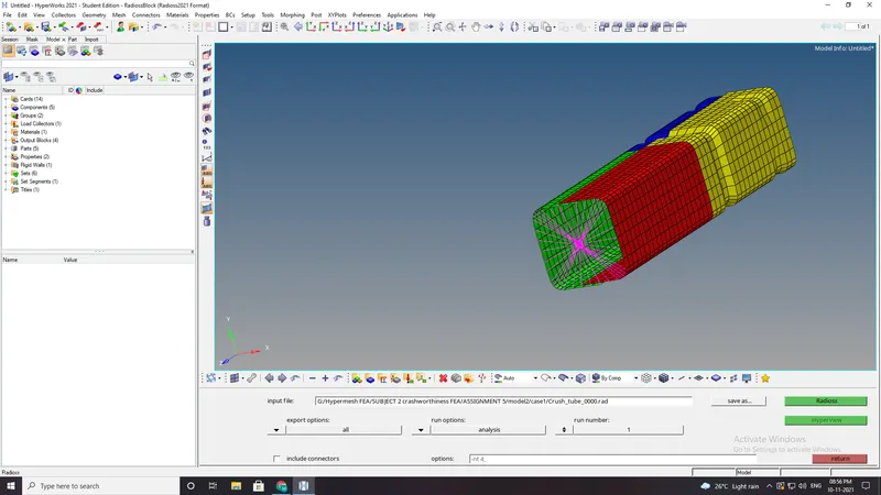
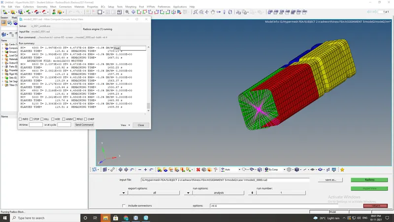
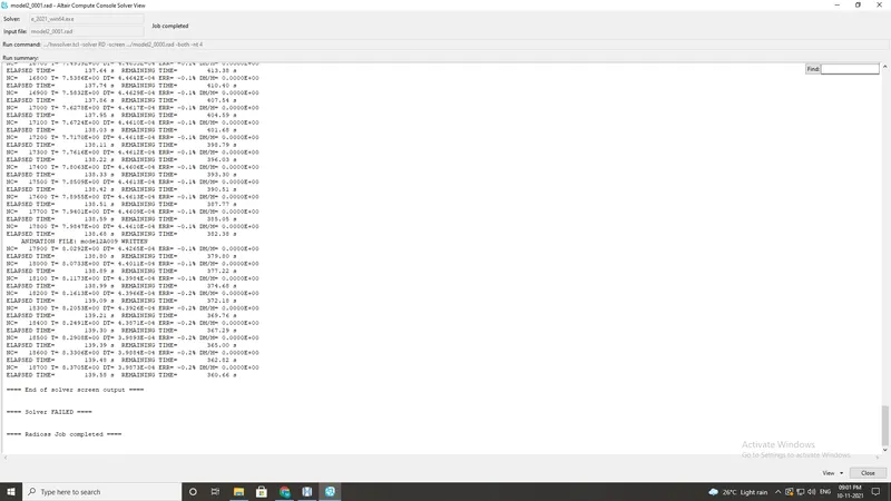
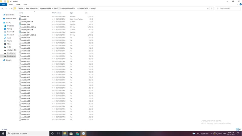
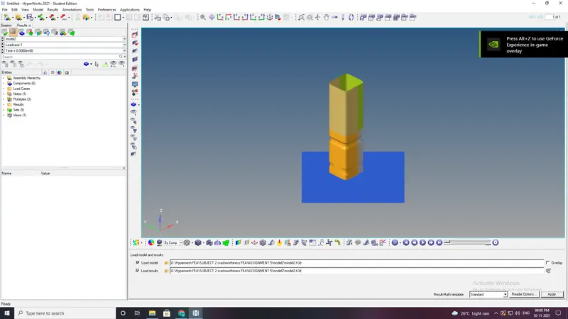
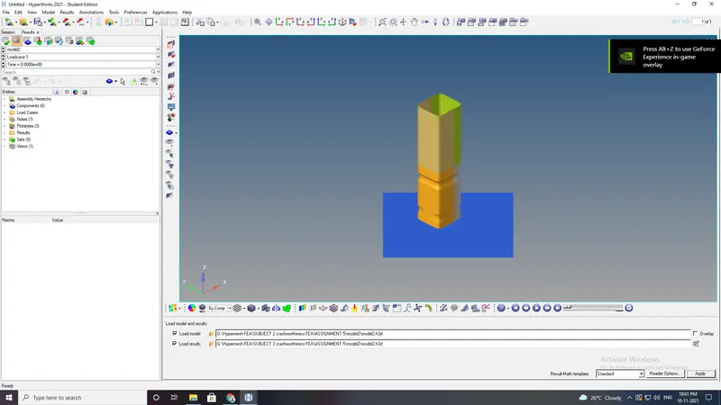
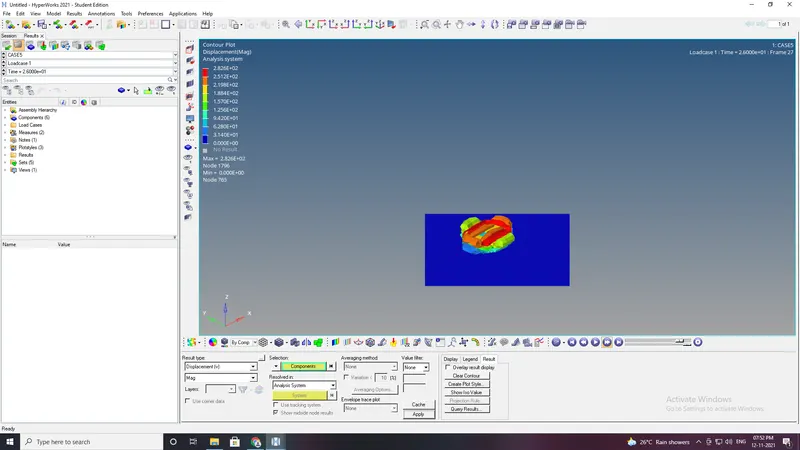
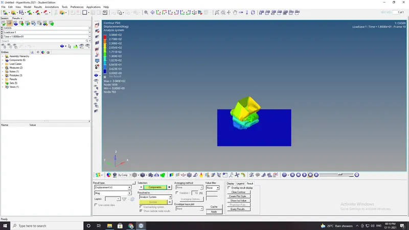
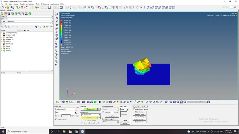
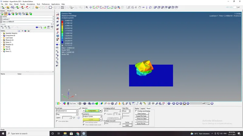
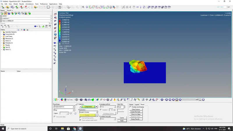
- Open hyperview to animation and contour plots from H3dfile.
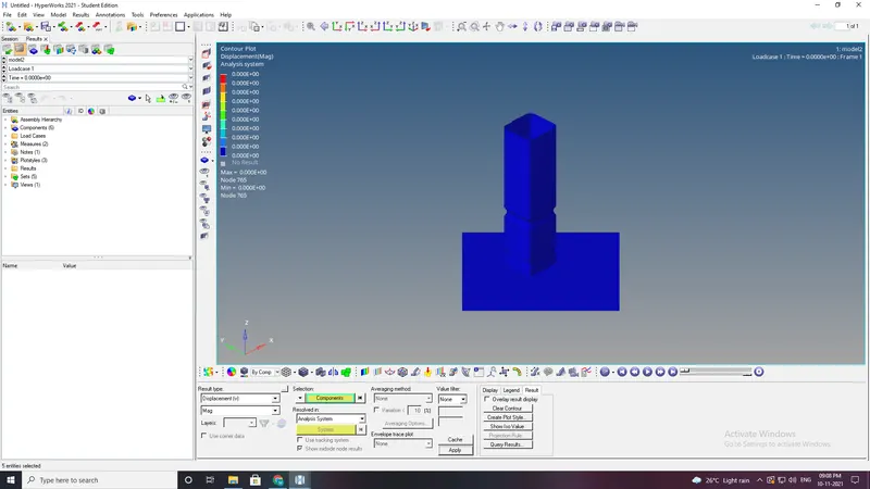
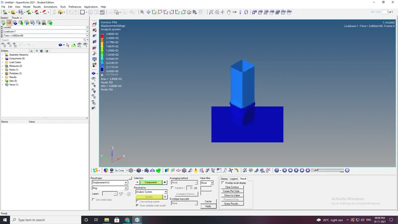
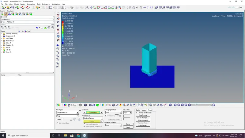
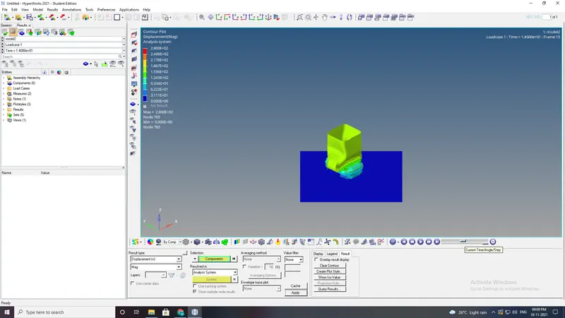
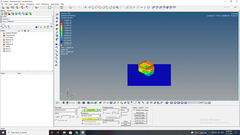
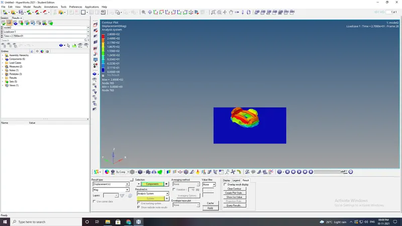
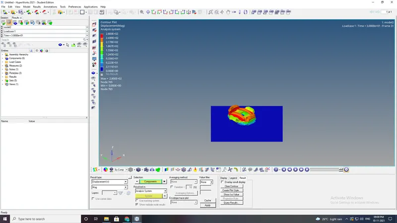
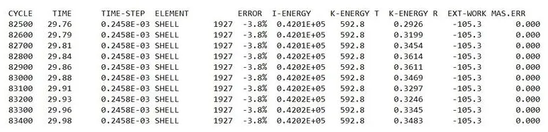
- open the hypergraphs 2d for observing the energy plot data from TA01 file.
- Energy error and mass error are within the limits- (less than 15% and 1% respectively) as the recommended shell properties are applied to the component
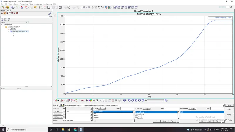
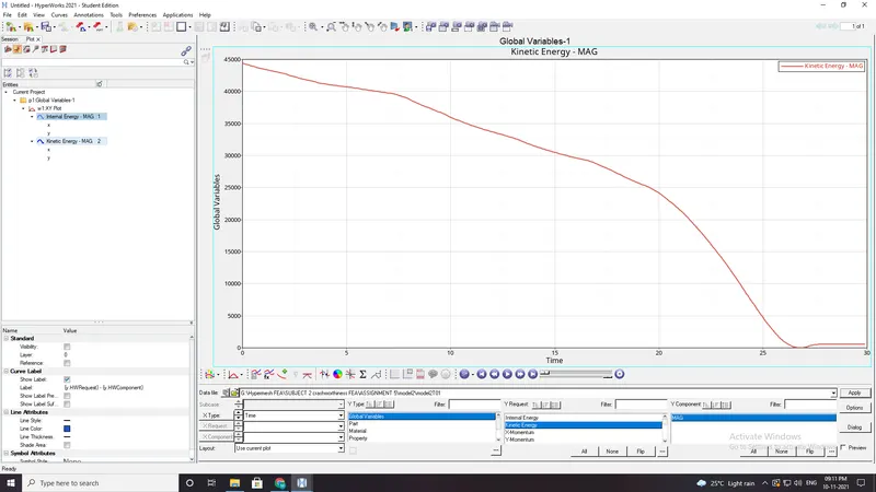
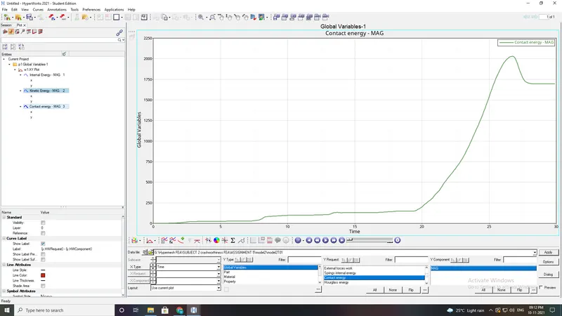
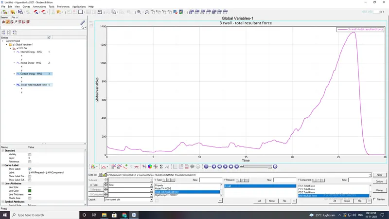
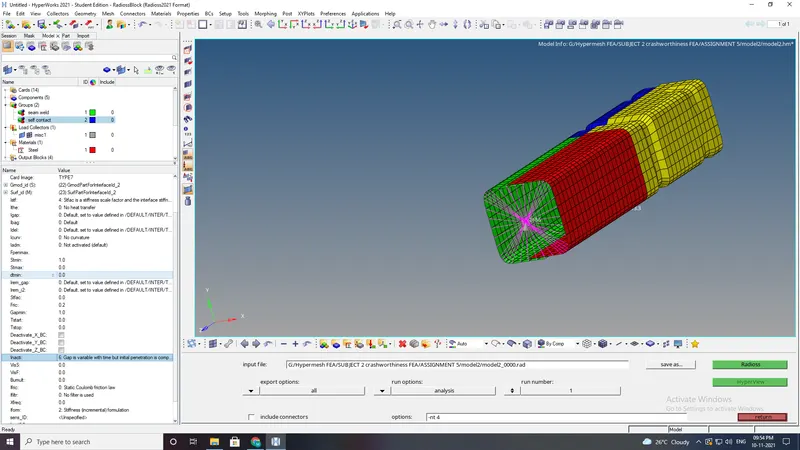
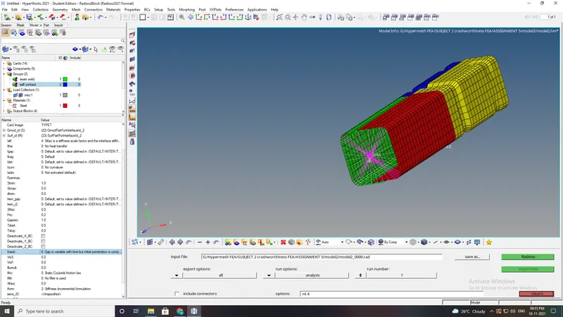
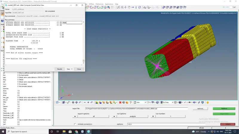
CASE2:Change the Inacti=6 and run.
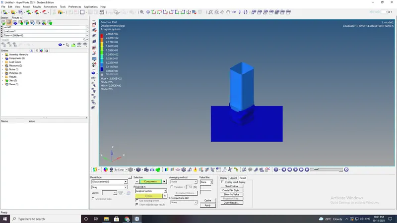
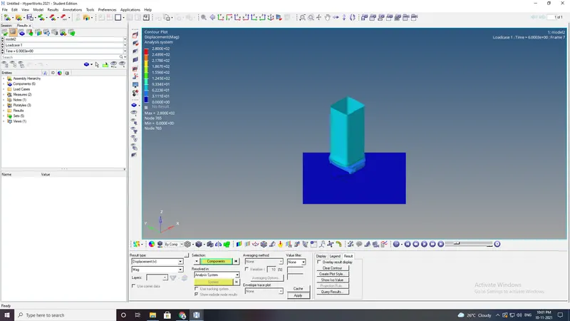
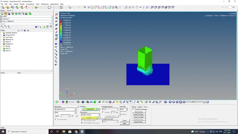
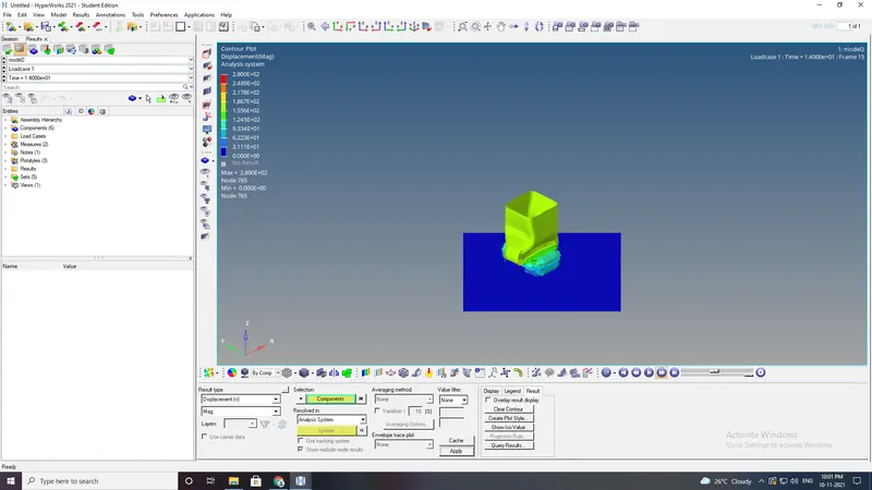
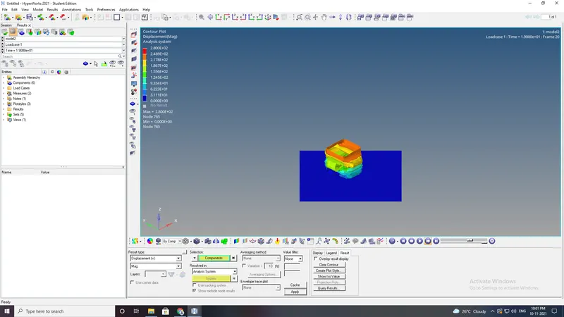
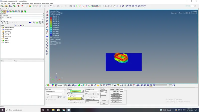
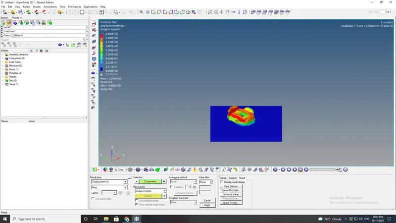
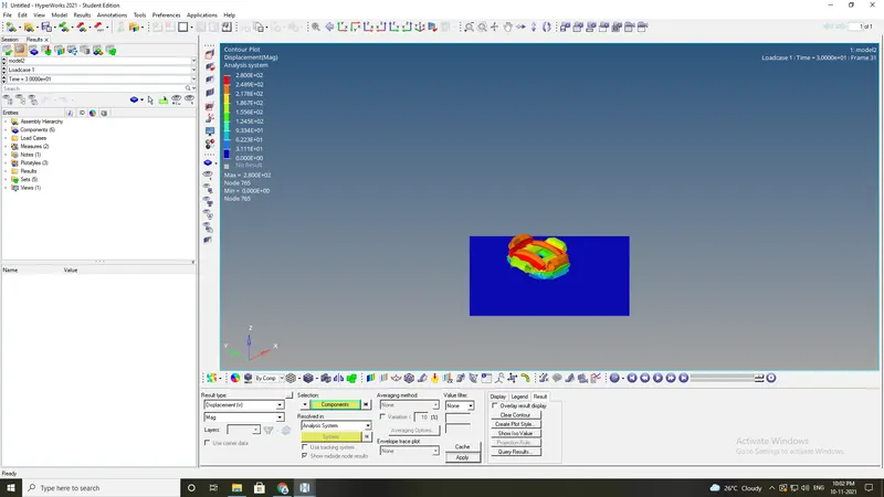
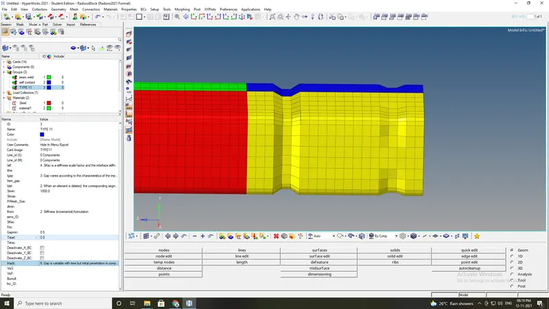
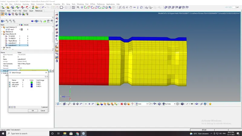
Case3:Create the type 11 contact and run.
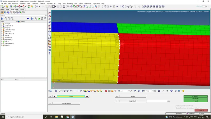
Case4:Remove both notches and remove boundary condition on rigid body node then run.
- In this case the notch need to removed.
- save the file in other folder
- delete the boundary condition BC
- remove the notches using allign node.
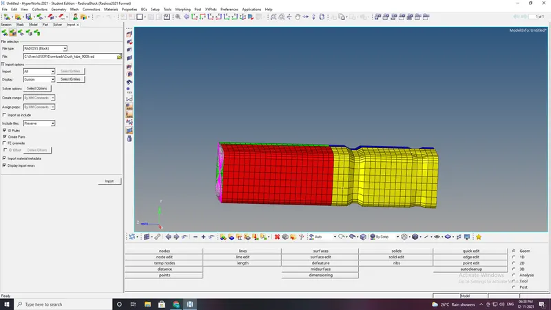
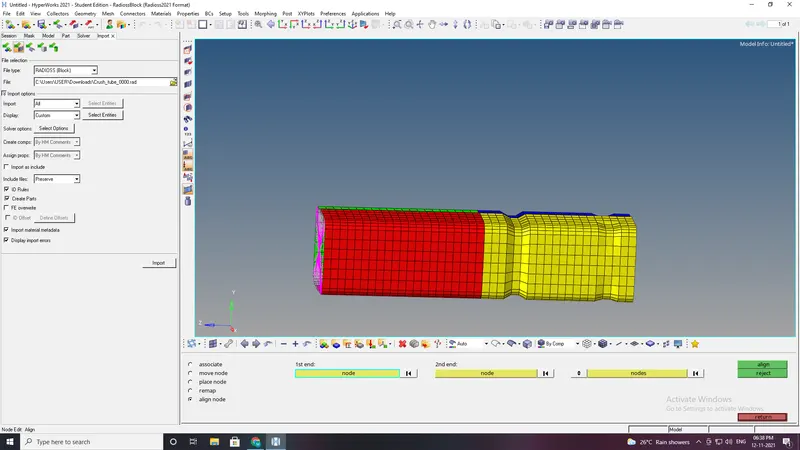
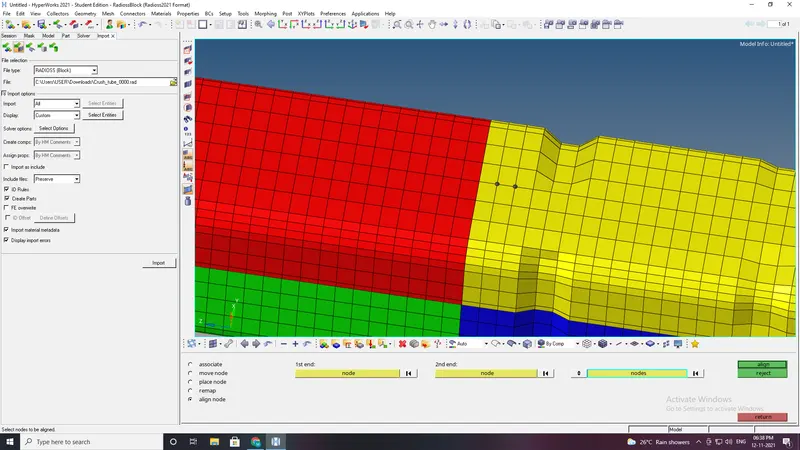
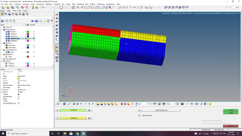
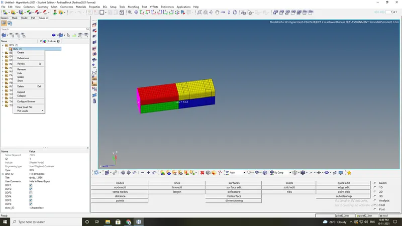
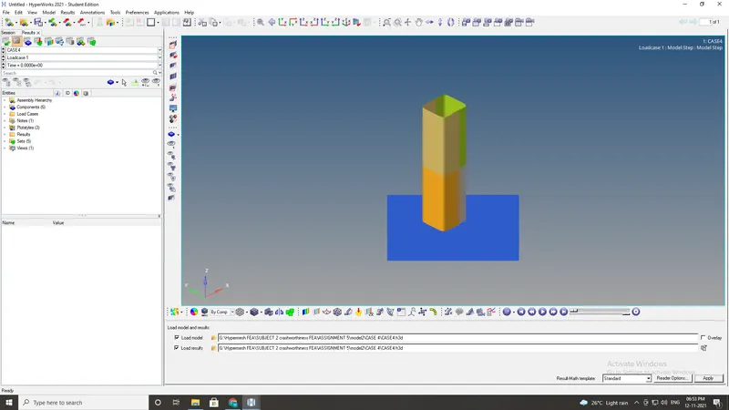
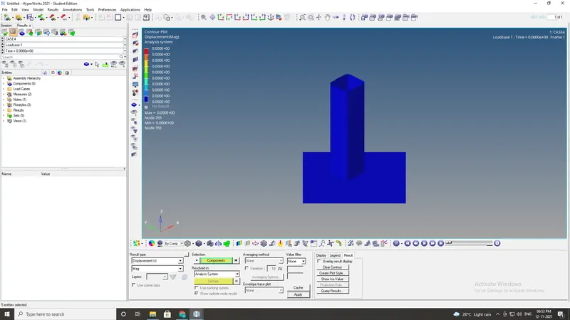
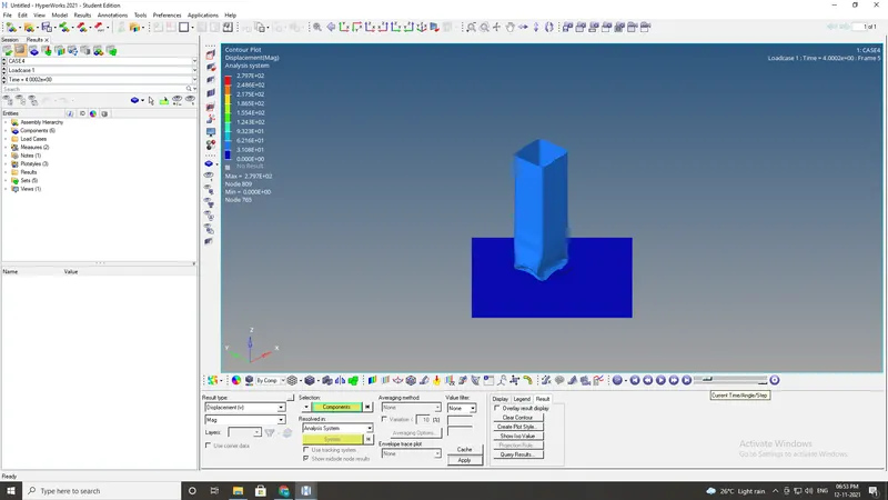
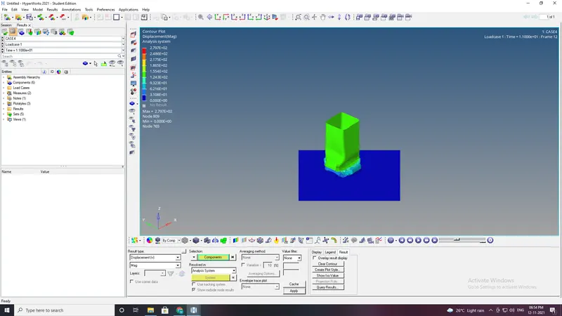
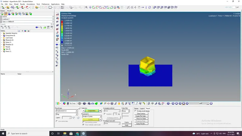
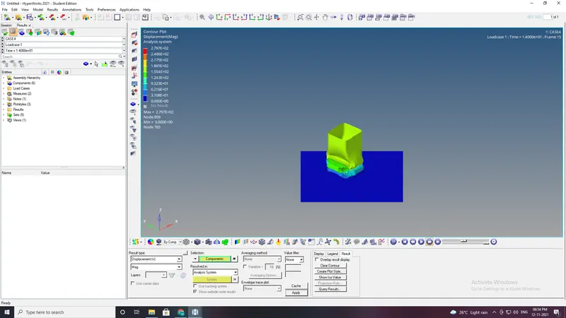
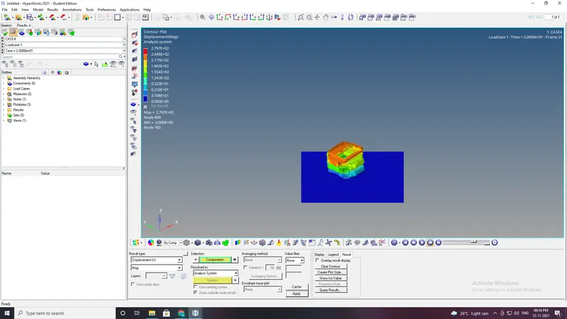
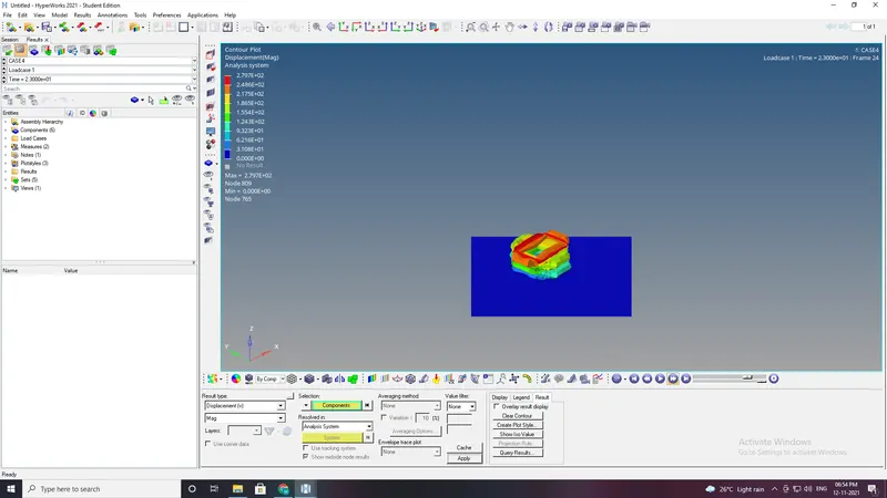
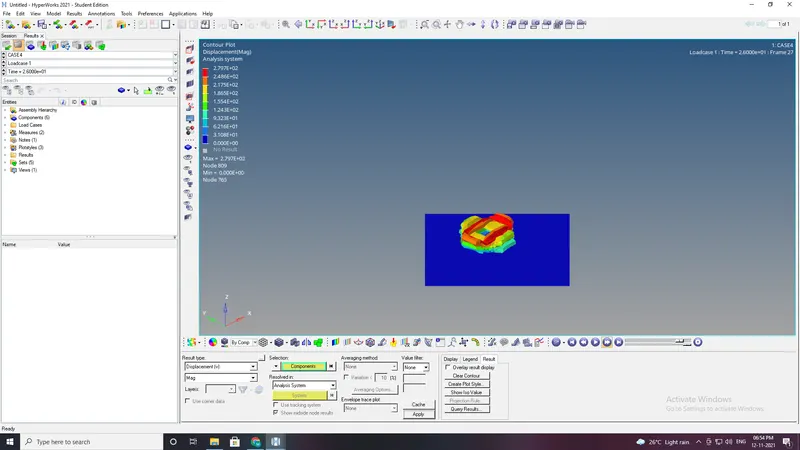
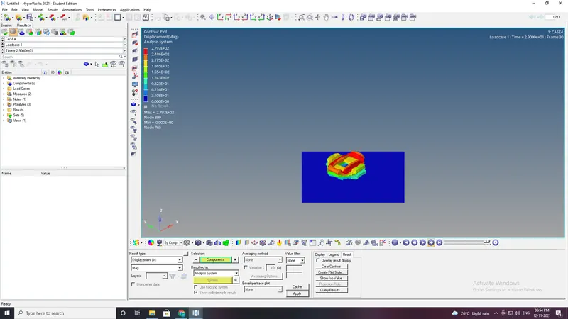
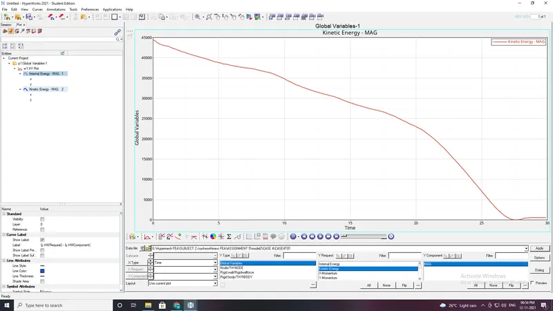
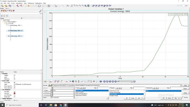
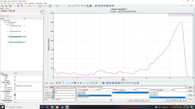
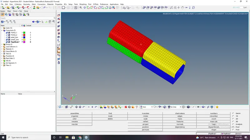
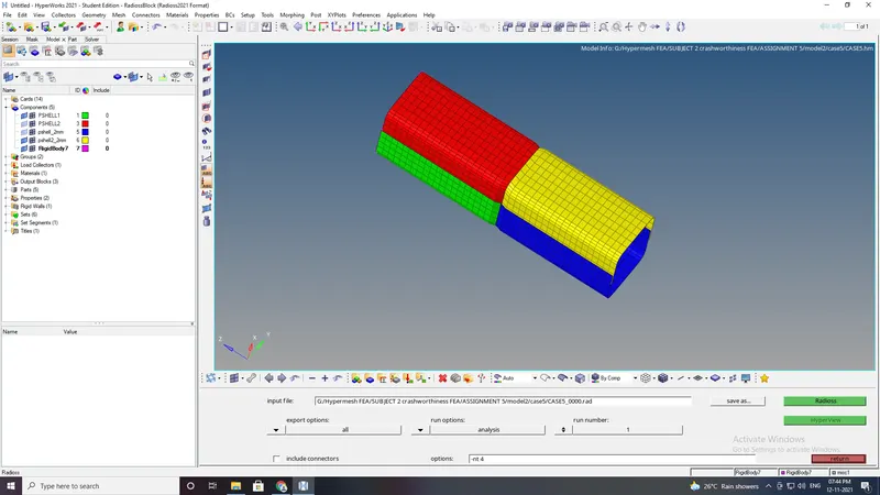
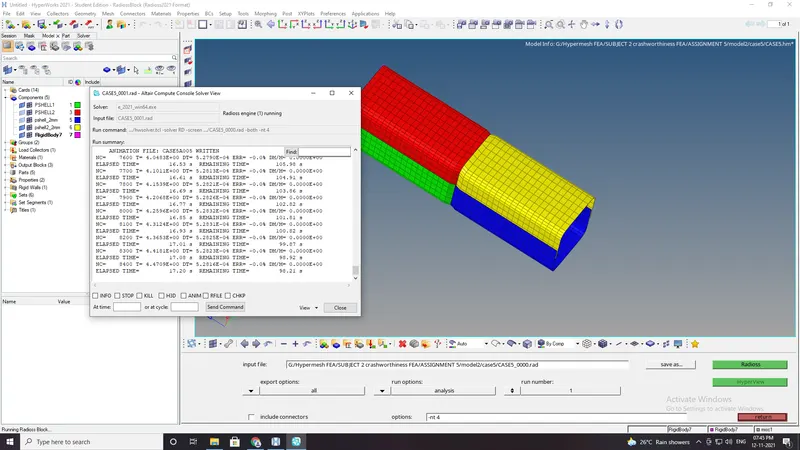
Case5:Create a new notch in the middle ,select the whole section and run.
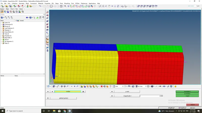
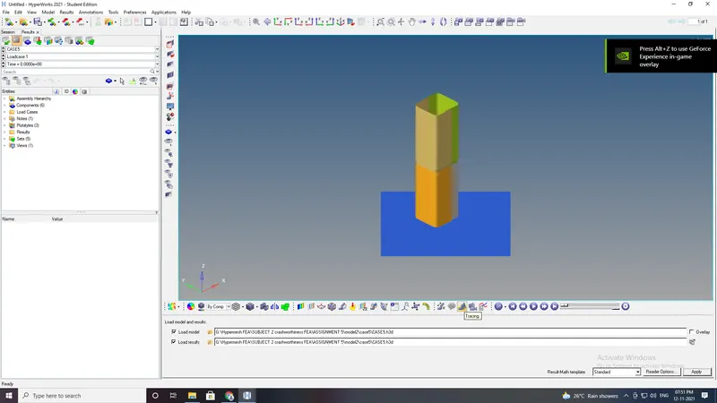
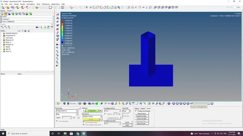
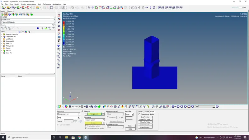
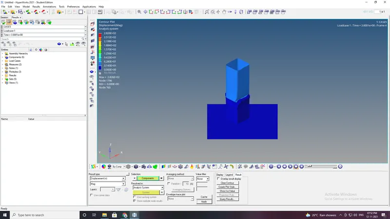
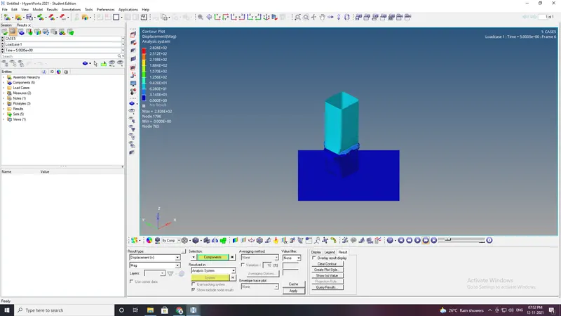
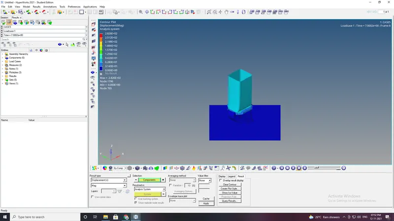
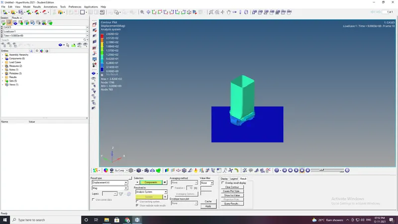
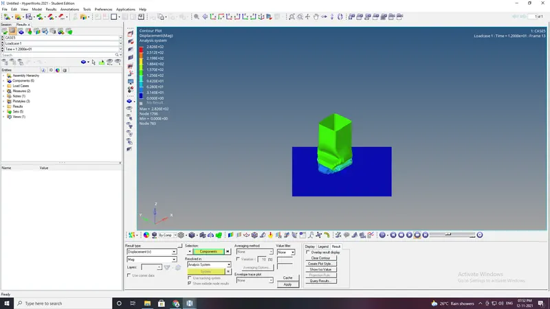
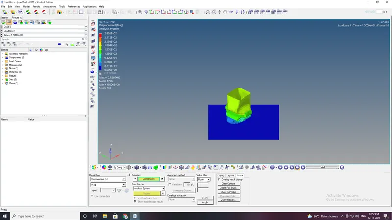
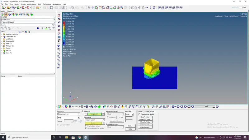
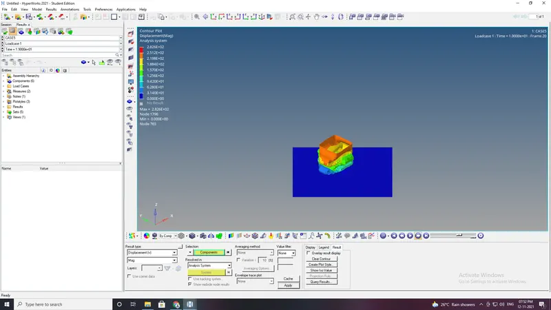
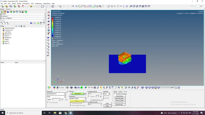
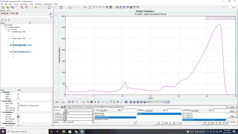
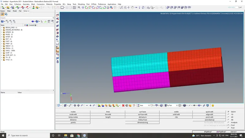
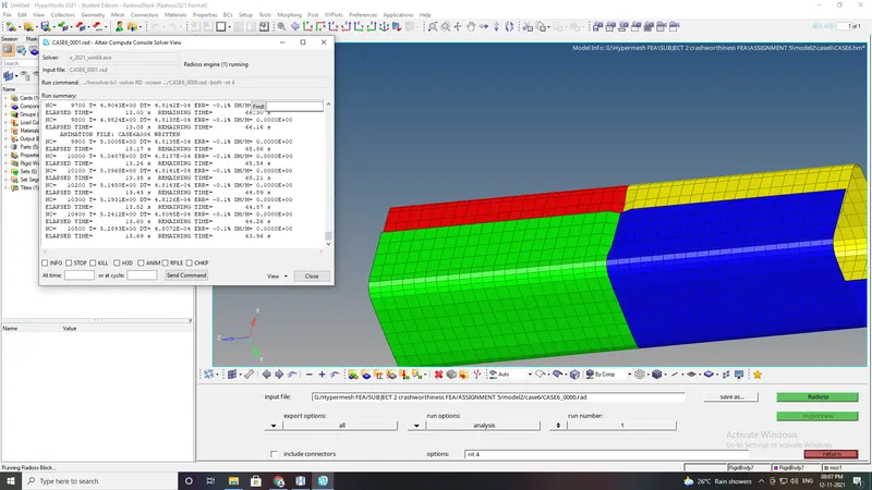
Case6:Create a new notch with nodes only from opposing 2 faces and run.
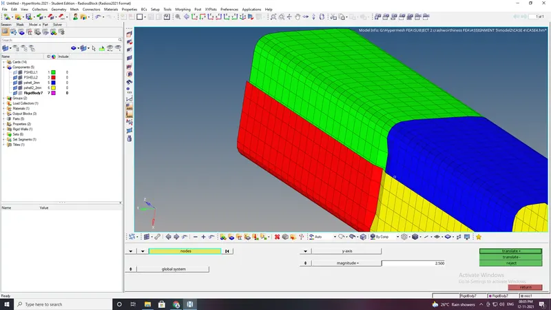
- In this case a notch should be created at the same place in the opposite direction.
- usng translate option.
- Notch is created.
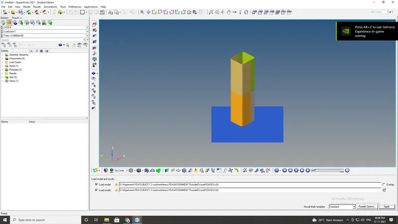
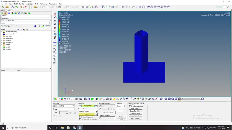
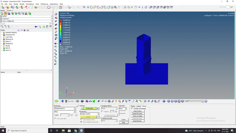
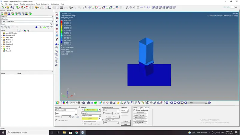
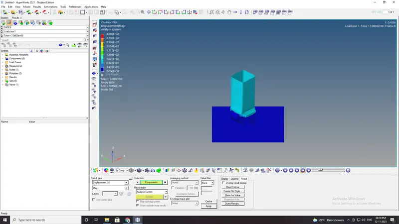
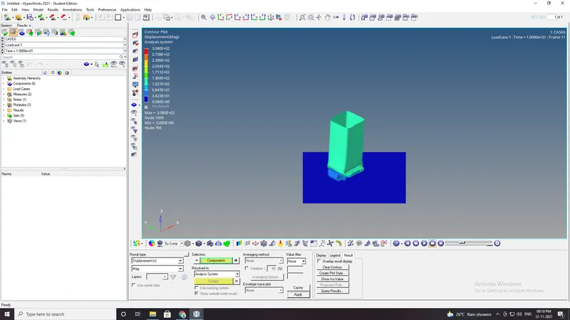
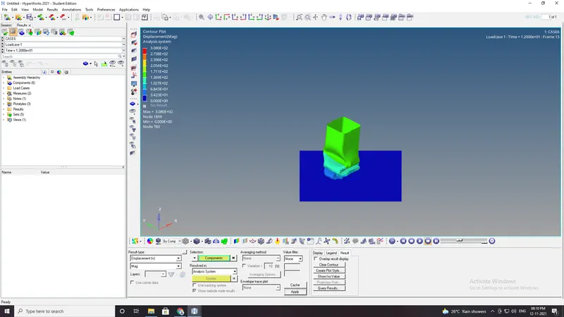
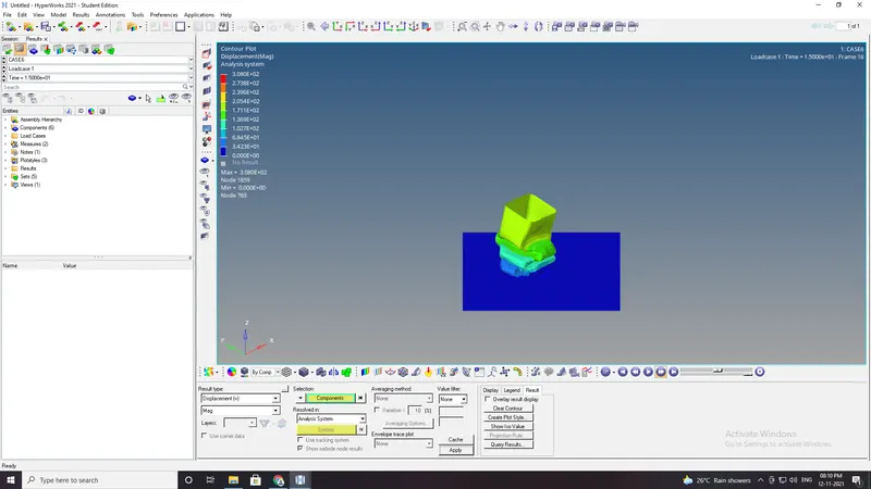
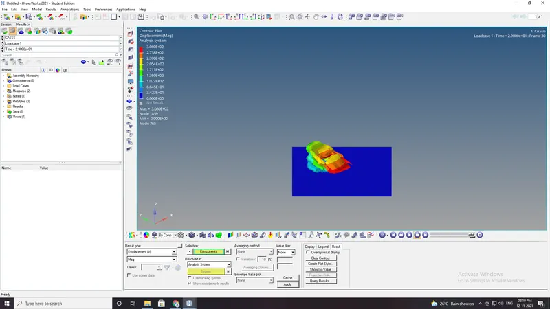
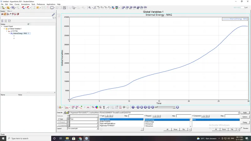
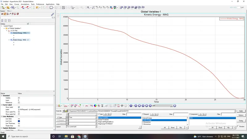
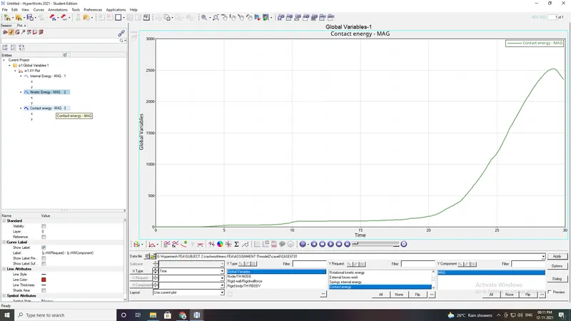
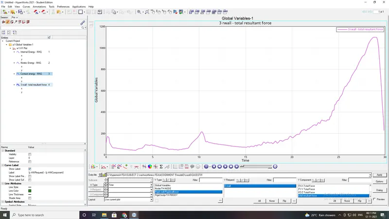
RESULT:
| CASE NO. | Particulars | Energy error(%) |
Mass error(%) |
max. contact force(N) |
Max rigid wall force(N) |
Max contact energy (KJ) |
Reason |
| CASE 1 | Running model as its is | -3.8 | 0 | 69.533 | 1400 | 2 | Node to surface contact type 7 |
| CASE 2 | change inactive = 6 | -4.8 | 0 | 69.533 | 1500 | 2.6 | No intitial penetrations found |
| CASE 3 | Type 11 interface | -3.9 | 0 | 112.5 | 1300 | 1.9 | Type 11 Edge to edge contact |
| CASE 4 | Removing notches and BC | -2.5 | 0 | 61.09 | 1200 | 1.3 | No boundary condition , flat surface |
| CASE 5 | creating new notch to middle | -3.6 | 0 | 61.94 | 1300 | 1.3 | Ability to absorb increased due to middle notch |
| CASE 6 | create notch only on opposte side. | -3.2 | 0 | 69.45 | 1100 | 1.5 | Due to opposing notches. |